Fatigue in Concrete Concerns Security and Stability of Flyovers
Concern about fatigue in concrete, is on increase in important concrete structures such as flyovers. In flyovers and allied structures when loading, in the form of repeated cycles, occurs for a large number, concrete undergoes phenomena of fatigue. Busy flyovers, in congested urban areas when display cracks in riding surface, or pedestrians; witness falling of chunks of concrete the phenomena creates panic in users. Basically, Fatigue and failure of concrete is a rare phenomenon. It is not a usual mode of failure of concrete structures. This Paper deals with important parameters of fatigue, strength of component materials under cyclic, loading and Codal provisions illustration of a bridge and or flyover affected by fatigue are suitably dealt with.
Notations – fc = compressive strength of concrete in MPa; Flim = fatigue limit in MPa
Dr C.S.Suryawanshi, Former Chief Engineer & Joint Secretary (P.W.D) Senior Consultant Mumbai.
Introduction
Many countries have recognized the importance of this effect and included design provisions for fatigue in their codes. A study of such phenomena in concrete in a bridge in arid zone and flyover, in coastal region constructed in recent past, on available data is illustrated here, pinpointing some of inadequacies and probable rehabilitation measures.
Fatigue & Material Properties
Unlike other materials, concrete is subjected to the effects of fatigue. Fatigue in a structural member occurs when permanent internal changes in the material viz internal micro cracking gets symptomized on surface initially in the form of visible cracks and later concrete turns brittle leading to failure of concrete. Generally, it is recognized as a cracking developed under repetitive loads that are less than the static load capacity. Fortunately, research has shown that the static load criteria under which most existing concrete structures have been designed have virtually precluded the possibility of fatigue failure in the primary load-carrying elements of the main members. Reports of fatigue failures in these primary elements are, apparently, nonexistent. Also, a recent laboratory study in Japan has indicated that the fatigue resistance of bridge deck slabs to moving concentrated loads is much less than to repeated fixed-point loads. This suggests that the progressive failure of slabs may, in part, be attributed to fatigue where repeated shear and torsional forces are applied. Fatigue is also regarded and experienced as a cause of cracking and failure in concrete pavements.Research on fatigue dates back to early 1900s. Most of it dealt with fatigue of plain concrete. In the 1960s, very extensive programmes on the fatigue of reinforcing elements were carried out in Europe, Japan, and the United States. Committee 215 of the American Concrete Institute published a report in 1974 that included an extensive list of references. More recent work has been directed to specialized applications. The proceedings of a colloquium held in 1982 by the International Association for Bridge and Structural Engineering contain a substantial number of current and relevant papers.
Phenomena of Fatigue
In general, mechanical properties of structural materials under dynamic loading, get improved with increasing rate of load application. In respect of concrete's dynamic ultimate strength in compression may be much greater than the static strength.A fatigue loading is a sequence of load repetitions. A distinction is made between high-cycle, low amplitude and low cycle, high-amplitude fatigue loading. The distinction depends on whether the repeated loading causes a failure at less than or more than an arbitrary number of cycles, usually considered in the range of 100-1000 cycles.
Behavior of Concrete Under Loads
In a simple explanation for fatigue, it is interesting to recall basis of stress-strain relation. Figure-1 shows the typical stress-strain curve of a test piece under compressive stress increased monotonically to rupture. The curve may be designated with following zones.
Figure 1: Typical stress-strain curve for concrete in compression
Strain is partly elastic and partly caused by non-reversible rupture of crystalline bonds, known as micro-cracking, hence the bend of the curve. The rupture is mostly by sliding between un-hydrated cement particles and is accompanied by reduction in volume. On condition that adequate moisture is present, the crystalline bonds will be re-established when the load is released or maintained steadily.
The release of the load will be as shown in Fig. 4-2, with a hysteresis loop and a residual deflection. Successive load cycles tend to a stable residual deflection with a hysteresis loop, the energy represented by the area of the loop being dissipated into heat.
The propagation of micro cracks under loads within this range is stable and the concrete can support an unlimited number of applications of such loads.
Zone B: unstable micro cracking; stress 0.55 fcu – 0.80 fcu. Micro-cracking is stable under a single application of load but increases with repeated applications until the micro-cracks link together to form macro-cracks which in turn progress in extent until rupture ensues. Strains increase with repetition of load. Final rupture is similar to rupture caused by a load monotonically increased and is accompanied by large strains; it is not brittle, As in zone A, after the release of the load or under a steady load, cracks both micro and macro will tend to seal up by the reestablishment of crystalline bonds accompanied by some increase in strength.
Figure 2: Typical stress-strain curves for repeated loadings in compression
The material is disaggregated and its apparent volume increases. After the release of the load (but not under steady load), cracks will seal up as in zones A and B.
Zone D: post-rupture stress - with a load possessing sufficient energy-potential (piled-up weights), strain (an extensible test rig) or dynamic (an impact)-as soon as the concrete reaches the maximum stress which it can support, it collapses.
Under steady, long-maintained loads but less good under repeated and high- energy load is perhaps as good a summary of what we know as any. Sufficient repetition of load in the upper half of this zone will cause cracking.
In respect of reinforced concrete members the behavior of concrete is similar upto zone A, however, thereafter it worth noticing.
Zone B: quasi-elastic behavior of the cracked section - The steel behaves elastically and the concrete is generally within zone A of material behavior (stable micro-cracking) but overlapping into zone B (unstable micro-cracking) at the upper end. The non-linearity of the concrete behavior causes the neutral axis to rise, resulting in a larger departure from linearity in the behavior of the beam.
Repeated loading causes increased deflection and crack widths, but the beam is probably able to support large number of repetitions. Release of the 'load leaves an appreciable residual deflection.
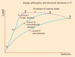
Figure 3: Effect of initial steel tension on load deflection curve of a prestressed concrete beam A Cracking Load B Rupture Load
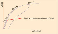
Figure 4: Typical load-deflection curve of a prestressed concrete beam
Zone D: Post-rupture load behavior - The ability of the beam to support large deflections but with decreasing load is primarily caused by the large non-elastic strain of the steel prior to rupture but the concrete makes a contribution. If the compressive flange is transversely reinforced with closed stirrups or links, its ability to support large compressive strains is greatly increased. The importance of this zone lies in the large area beneath the deflection curve and, in consequence, in the large energy at rupture, energy of which a small fraction only is resilient but nearly all of which is dissipated. This renders reinforced concrete ideal for high-energy loads (earthquake, explosion) of rare occurrence.
Pre-stressed Concrete
Given a concrete section and a cross-sectional area of high-tensile steel at a defined location in the section, the ultimate strength of a pre-stressed concrete beam has been determined subject only to such variations as are described below. Brittle failures similar to those in reinforced concrete can occur with extreme proportions of steel, but it will be assumed that such proportions have been avoided. There then exists an extra variable at the control of the designer - the initial tension in the steel; the behavior of the beam will differ profoundly according to the value chosen for this initial tension. Figure -3 shows the range of behavior.At one extreme, where the steel has not been tensioned, behavior is similar to that of reinforced concrete. The difference is that, since the steel is of high tensile strength, the steel strains are large and the neutral axis rises rapidly to near the upper surface and the full strength of the steel cannot be utilized. The cracking load is small and well defined.
At the other extreme, the steel is stressed to near its elastic limit. The cracking point is little lower than the rupture load. Since the steel has been given an initial extension, less strain is needed for it to reach its ultimate tensile strength but here the steel is at its maximum.
With intermediate values of initial tension in the steel (that shown represents a typical design according to current practice whereby the tension in the steel after relaxation is approximately 0.6 fcu the cracking load will be much lower, the ultimate load slightly lower than that with maximum initial tension.
What is the significance of these differences of behavior?
Note first the significance of the cracking load in pre-stressed concrete. From zero load to cracking load, there is little difference in the value of the force in the steel, the increased bending moment being supported by a displacement of the centre' of thrust in the concrete, thus increasing the moment arm. In concrete, stresses vary between limits fixed by the designer as being capable of being supported indefinitely. As a result, until loads appreciably exceed the cracking load, there is no danger of failure under repeated loads.
In curve I (maximum initial tension in steel), the cracking load is a high proportion of the static rupture load; so too is the fatigue limit-indeed, it is doubtful whether any known structural material can withstand indefinite repetitions of so large a proportion of its static rupture load. On the other hand, deflection at rupture is small as is the energy to cause rupture; behavior tends towards the brittle. This is the extreme of resistance to repeated loads.
In zone A, residual deflections on release of the load are small: as we have seen repetition of the load in this zone will not produce failure. Fig-4.
In zone B, residual deflections on release of the load are larger but still small. The area under the curve after loading is large but this energy is not dissipated but for the most part stored resiliently and the beam is still quasi-elastic. The inflection in the curve of deflection is of value in redistributing the load in redundant structures, especially since this redistribution is reversible and residual deflections on release of the load remain small. The beam in this zone can support steady loads indefinitely but repeated loads can cause failure.
In zone C, residual deflections on release of the load are larger but still much smaller than those in curve II. Dissipated energy is significant but a large part of the energy absorbed is restored resiliently until rupture is near. Steady loads in this zone will cause failure as will repeat loads.
From the foregoing fatigue can be simply defined as
The weakness or breakdown of material subjected to stress especially a repeated series of stresses
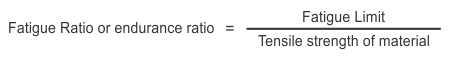
Fatigue Limit – Tensile Strength of Material
Premature Failure Syndrome (PFS)
Under continuous repetitions of loading, a crack forms at a point of high stress concentration, on repletion of stress the crack slowly spreads under, the member raptures without measurable yielding. Although the concrete is ductile, the fracture looks brittle.
Endurance Limit (EL)
Concrete, has a well defined yield point and has a known endurance limit, which is the maximum unit stress that can be repeated, through a definite range, on an indefinite number of times without causing structural damage. Generally, when no range is specified, the EL is intended for a cycle in which the stress is varied between tension and compression stresses of equal value. For a different range if 'f' is EL, 'fy' the yield point and 'r' ratio of minimum stress to the maximum than
The range of stress may be resolved in two components, a steady or mean stress and an alternating stress. The EL, sometime is defined as the maximum value of alternating stress that can be superimposed on the steady stress on indefinitely large number of times without causing fracture.
If f is EL for completely reversed stresses 's' the steady unit stress and fs the ultimate tensile stress, than alternating stress =

Where 'n' lies between 1 – 2 depending upon mechanical properties of material.
Fatigue Strength of Component Materials
When the phenomena of fatigue alone, is critically examined it will indicate - Test data on the fatigue strength of concrete or reinforcing steels are usually presented in the form of S-N, or (Wohler, diagrams). Where S is a characteristic stress of the loading cycle, (often either the stress range or a function of the maximum and minimum stress), and N is the number or cycles to failure. Fatigue' data on concrete or reinforcing steels have commonly been shown in semi-log plots, where S is plotted linearly as a dependent variable and life is plotted as an independent variable on a log scale. In this form, the mean of the data can often be represented by a straight regression line.Fatigue life is considered to occur in three stages: initiation of cracking, propagation of cracking, and fracture. In the propagation stage, micro-cracking occurs in the concrete or cracking is growing in a steel element. During most of this stage, the cracking grows slowly, followed by a short period of more rapid growth leading to fracture.
In designing for fatigue, recognition must be given to the variability that is inherent in the phenomenon. The mean regression line of a set or fatigue test data is shown in Fig- 5. The assumption of a normal distribution of the fatigue lives about the mean is usually acceptable. With this assumption, for example, it may be stated that the probability of failure, p at the lower dashed line is 5%. This dashed line is located 1.96 times the standard deviation, s, of the data below the mean. Fatigue data on concrete have been represented in this manner.
It is more common and more useful for design, particularly with fatigue data on steel, to utilize a lower tolerance limit on the data. A tolerance limit associates a confidence level with a probability of survival. This confidence level is dependent on the number of test results in the sample. For the data shown in Fig-5, 95% of the test results are expected to exceed, at a 95% confidence level, the lower tolerance limit. This limit is about twice the standard error of estimate or N below the mean.
Confidence intervals are also commonly shown on fatigue test data. These intervals, for example at the 95% level, indicate the range in which 95% of the means or the population represented by the' data are expected to be included. However, it is never known if the S-N curve of the population actually lies within the confidence interval.
Plain Concrete
When concrete is subjected to increasing compressive load, it is observed that the volume of the concrete ceases to decrease, and instead begins to increase at a stress level as low as approximately 50% of the compressive strength. The initial deviation from linearity of the relationship between stress and decrease in volume is noticed to be related to a significant increase in micro-cracking of the aggregate paste interface, while the stress at which the volume began to increase was related to a noticeable increase in micro-cracking through the matrix. Repetitive loading appeared to have a significant effect on the growth of micro-cracking. As a result, the fatigue of plain concrete may be considered to be a process of progressive, permanent changes occurring within the concrete matrix under repetitive loading.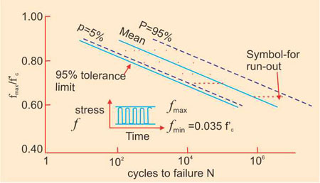
Figure 5: variability in fatigue life of concrete in composition
Under cyclic compressive loading of concrete specimens, a number of investigators have observed a decrease in the measured value of pulse velocity and an increase in acoustic emissions. These changes are related to the growth of the micro-cracking. More important to the designer is the increase in deformation that occurs during repeated loading, as illustrated by the data obtained by Holmen and shown in Fig - 6.
A rapid increase in strain occurs between and about 10% of the total life, Nr. The increase in strain between 10 and about 80% is slow and uniform, after which the strain increases at an increasing rate until failure occurs. Furthermore, it appears that the strain consists of two components, one related to the micro-cracking and the other which is time development and related to creep deformation. Expressions for estimating the strain have been developed.
Cyclic Compression Fatigue
Numerous investigators have found that the fatigue life of a common group of concrete specimens tested in compression, each under a constant amplitude loading with the stress, f, varying from the same minimum to different maximum, may generally be presented by a straight line, as illustrated in Fig-5. Further more, there is no apparent endurance limit below which the concrete will sustain an unlimited number of repetitions, although it should be noted that very little data are available for loading greater than 107 cycles.An expression for the fatigue of concrete in compression based on linearity of the relationship between fmax fmin and log N, can be expressed:

in which a value of b based on a review of available data, equal to 0.064 was given.
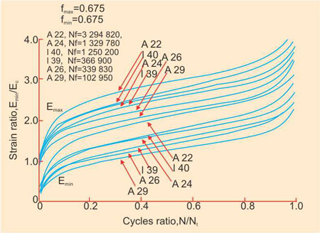
Figure 6: Variation in measured strain: €0 is the maximum strain in the first cycle; the frequency is 5Hz
In design equation for the fatigue of concrete in compression has been included in the Tentative recommendations for the limit state design of concrete structures by the Japan society of Civil Engineers, as follows:
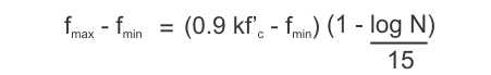
Where k is the coefficient taken equal to 0.85 to consider the difference in concrete strength measured using standard cylinders and the in-place strength. This equation was reported to have been based on the fatigue life to a probability of failure of about 5%.
Cyclic Tension
A number of investigations have shown that the fatigue strength of concrete under loadings producing axial, splitting or flexural tension is about the same as for compression. Cyclic loading from compression to tension has been reported to cause more damage than zero-to-tension loadings.Effect of Material Properties
Numerous investigator have studied the effect of such factors as cement content, water/cement ratio, curing conditions, age at loading, amount of entrained air and type of aggregate. Except for the latter factor, there is general agreement that these factors affect fatigue strength in a proportionate manner to the static strength of the concrete, as directly given by the previous expressions for fatigue strength. Furthermore, the fatigue strength of mortar is also comparable to concrete when expressed as a function of compressive strength.
In practice, structural concrete members are normally subjected to randomly varying loads with periods of rest. In laboratory tests on concrete specimens subjected to varying flexural stresses, rest periods were beneficial, increasing the fatigue strength at 107 cycles, expressed as fmax/fc by about 10%. Low amplitude cyclic loading interspersed in higher amplitude loading also has a beneficial effect.
Commonly used Miner's hypothesis to determine the accumulation of fatigue damage under varying stresses can be expressed as:

Where Ni equals the number of constant amplitude cycles at stress level i, Nfi equals the number of cycles that will cause failure at that stress level i, and equals the number of stress levels.

Cyclic Flexural Fatigue
In tests conducted on beams with non-pre-stressed reinforcement, a single reinforcing element has commonly been used. Fatigue failures of these beams occur suddenly, with little Sign of distress. Very few tests have been conducted on beams with multiple non-pre-stressed reinforcing elements. However, fatigue fractures of reinforcing bars were induced in bridges in the AASHTO road test during special testing after the completion of the vehicular traffic tests.These beams may not exhibit significant distress before failure occurs, because of the high bond between the steel and concrete, unless there is sufficient redundancy in the overall structural system to permit redistribution of the loading.
Multiple reinforcing elements have generally been used in the tests on beams containing pre-stressed steel. Fatigue failure of these beams have occurred only after significant signs of distress in the form of the development of a very wide crack and increasing deflections. As on the load-deflection curve for a pre-tensioned pre-stressed concrete I-beam in which a flexural fatigue failure occurred is shown in Fig- 7, along with a cross-section through the beam showing the location of the six 7/16 in (11 mm) diameter seven-wire 270 000 psi (1860 MPa) grade strand. Compressive strength of the concrete was 7120 psi (49 MPa) at the time of test. This beam was subjected to an initial loading of approximately 80% of the ultimate flexural capacity of the specimen, which was sufficient to fully develop flexural cracking and also cause significant inclined cracking in both shear spans. Next, the beam was subjected to 2 million cycles of a normal design loading with induced moments in the center of the span ranging between 19 and 45% of the flexural capacity of the specimens. Under this loading, the stress in the bottom fibers of the beam ranged between 890 psi (6.14MPa) compression and 440 psi (3.0 MPa) tension, computed on the basic of an un-cracked section. The tensile stress was approximately equal to 5.2 "f'c psi (0.44 √f'c MPa). No damage was observed. The range of the cyclic loading was subsequently increased to between 19 and 50% of the flexural capacity. At the maximum load, the nominal tensile stress in the bottom fibers was 660 psi (4.5 MPa) or 7.8 √f'c psi (0.65 √f'c MPa. The beam sustained 570,000 cycles of this increased above design loading before the test was stopped because of extensive fatigue damage. The first indication of increased deflection corresponding to fatigue damage was evident at 455,000 cycles of the above design loading. After the test was conducted, the pre-stressing strand was exposed and a total of 21 wire fractures were found in the three lower level strands. Four of these fractures were at locations other than at the major cracks.
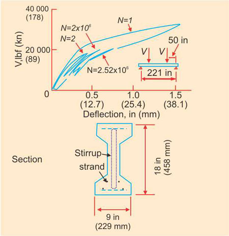
Figure 7: Deflection of a prestressed beam under static and cyclic loading (Reproduced from Hanson, J.M., Halsbos, C.L. and Vanhorn, D.A., 'Fatigue tests of prestressed concrete I-beams', J.Struct. Div. ASCE. Vol. 96 pp 2443-2464, 1970)
Cyclic Shear Torsion and Bond Fatigue
The effect of shear, torsion and bond are in many a cases quite closely related. For example, the development of inclined cracking will, in the absence of adequate shear reinforcement lead to increased stress in the flexural steel, which may affect the bond strength. On the other hand slip of reinforcement in an adequately reinforced member may induce a shear failure particularly in prestressed beams.A number of investigations of the shear fatigue behavior of both non-prestressed and pre-stressed beams have been reported. It has been observed that the shear fatigue strength of non-prestressed beams without web reinforcement was approximately 60% of their static shear strength. Fractures of stirrup reinforcement have been reported in fatigue tests on both non-prestressed and prestressed beams.
Designers should recognise that inclined cracking will occur at lower stress under cyclic loading than under static loading. This, of course, is generally regarded as the limit state in a beam without web reinforcement. The number of cycles will be related to the tensile fatigue strength of the concrete. Non-prestressed beams without web reinforcement will therefore have lower shear fatigue strength than prestressed beams. For design, the shear fatigue strength should probably not be taken greater than one-half of the static design shear strength. Pre-stressing contributes to the shear strength of a beam without web reinforcement by imposing a compressive stress in regions where inclined cracks may originate. The shear fatigue strength of these members may be estimated by reducing portion of the contribution which is dependent on the tension in the concrete to one-half of the usual value.
Torsion
Information on the torsional fatigue resistance of concrete members is limited. A recent investigation confirmed that the fatigue properties of plain and prestressed concrete under torsion were about the same as those of concrete under compression or flexure.Unintended or unrecognized structural interactions may induce torsion in slabs and beams. These torsional forces may be surprisingly large in uncracked members, where the resistance is dependent on the tensile strength of the concrete. Under cyclic loading the torsion may cause cracking that will subsequently contribute to the deterioration of the member.
In torsion, as in shear, it was found that the primary stresses are redistributed to the bars after cracking, and that the torsional stiffness is reduced. However, failures occurred due to fatigue of the concrete rather than the steel.
Bond
Research review on bond fatigue, leads to the conclusion that in the absence of cracks in the anchorage zone, the bond strength for 1 million cycles will be about 60% of the static strength. When cracking occurs, the bond fatigue strength will be strongly dependent on shear effects.Two areas are of particular importance for bond fatigue - railroad ties and pre-stressed beams with 'blanketed' strands.
Design Parameters and Codal Provisions
Structural concrete members are normally proportioned to carry factored service loads. Fatigue is a serviceability condition that must be checked in the design process if the member is subjected to cyclic loading. This check is made by computing minimum and maximum stress levels under the anticipated cyclic loading at any potentially critical location and comparing the stress variation to the fatigue strength of the material. If there is variability in the cyclic loading, some method of accumulating the effect of the different load levels must be included. Miner's hypothesis, as expressed in Eqn-2-5, is frequently used for both the concrete and steel components of the member.A satisfactory estimate of the stress levels in both the steel and the concrete can usually be made using the ordinary principles of flexural mechanics. However, these procedures become quite complicated for pre-stressed beams subjected to cyclic loading that induces cracking. These members are often referred to as partially pre-stressed. Aids have been developed for the analysis of these members.
While simple in concept, a check of a member for fatigue can become quite complicated when, for example, different load patterns are required to obtain maximum or minimum stress levels at a selected location. However, in many cases, the question will be whether or not the concrete member is on the threshold of fatigue distress. Hence it will be mainly important to project the numbers of cycles of maximum repeated loading which the member may conceivably resist during its design life.
Most building codes governing the design of concrete structures subjected to in shear reinforcement can be calculated as follows:
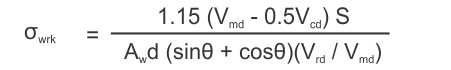
σwrp = σwrk (Vpd / Vrd)
Where Vmd is the design maximum shear force, Vcd is the design ultimate shear force resisted by concrete, Vpd is the applied design permanent shear force, Vrd is the applied design variable shear force, Aw is the area of shear reinforcement within a distance s, d is the effective depth and θ is the angle between shear reinforcement and the longitudinal axis of the member.
Fatigue limit states for reinforced concrete beams may generally be examined only for longitudinal tensile reinforcement and shear reinforcement. Fatigue limit states for reinforced concrete slabs may generally be examined only for tensile reinforcement. The examination of fatigue limit state for reinforced concrete columns may generally be omitted.
Codal Provisions
- Indian Standards
- Plain and Reinforced concrete code of practice IS-456.
- Indian Roads Congress Publication 21
A standard specification and code of practice for Road bridge Section-III deals with along aspects does not contain any provision for evaluation of fatigue, but contain provision. Provision of exposure conditions for concretes from durability point of view. - Indian Roads Congress Special Publication 37
Provision about rating of bridges are outlined along with procedure to be adopted in evaluating the strength of existing bridges. Indian Standards – Code of Practice – Plain and Reinforced Concrete is 456:2000 contains design requirements of R C Members. Amongst various requirements includes elastic deformation and creep of concrete (6.2.3 & 6.2.5) and limits the concrete to follow law of elasticity as long as the stress in concrete does not exceed 1/3 of its characteristic strength.
- Foreign Codes
European Codes
Several European countries have codes containing fatigue design provisions. The following provisions are included in Appendix f of the 1978 CEB-FIP Model code for concrete structures.
CEB-FIP Model Code For Concrete Structures 1978
General
Fatigue failure of a material is failure due to frequent repetition of stresses lower than its strength under static loading.
The stresses that are comparable with the fatigue strength should be determined by means of elastic methods, taking into account the dynamic effects, the effects of creep, the losses of pre-stress etc. These stresses are defined as follows:
σmax corresponding to a frequent action repeated 2-10th times at its maximum value;
σmin corresponding either to a quasi-permanent action or to a frequent action repeated 2-10th times at its minimum value, as the case may be.
The condition to be checked is
Δ6 = 6max - 5 min ≤ Δfrep / δfar
Δfrep denoting the strength under repeated load effects.
Fatigue Strength of the Concrete
The fatigue strength is defined as the 50% fractile deducted from test results.
Fatigue Strength of the Steel Reinforcement
For the steel the characteristic strength is the 10% fractile and for the anchorage devices the 50% fractile, deducted from tests in which σmax is repeated 2-10th times and where:
σmax = 0.7 fyk (or f0.2k) for reinforcing steel
σmin = 0.85 f0.2 for pre-stressing tendons.
The reduction of the fatigue strength owing to curvature, welding, mechanical connections, end anchorages etc. should be taken into account in the calculations, preferably on the basis of test results.
Special Considerations
The task is to take into account all the stress concentrations which are liable to affect fatigue behavior but which are beyond the usual objectives of stress checks.According to the notes (which accompany Appendix f), the provisions represent a simplified approach of practical character which is appropriate for most conventional structures. Only in special cases, it is necessary to check the cumulative effect of the repetitions at different stress levels, using the Palmgren-Miner rule for example, with appropriate limitations and a defined load spectrum, related to the expected life term of the structure. The random nature of the load repetitions is not taken into consideration.
Normally, the following numerical values are introduced:
For steel, Yfat is applied to the characteristic value and is taken at 1.15 i.e. frep/δfat = f&thet
For concrete, and for the anchorage devices Yfat is taken equal to 1.25 and applied to the mean value i.e. frep/Yfat = Vfcm/1.25 or Δfsm/1.25
In the absence of test results or practical experience, the following lower limits are accepted (σmin = 0) for fcm2
0.6 for the stresses in the concrete and for bond stresses in high bond bars.
0.4 for the bond stresses in smooth found bars.
In the absence of test results, the following values can be adopted for Δfcm (σmin= 0)
Smooth bars 250 MPa
Prestressing tendons (without bond due to deformed shape) 200 MPa
Prestressing tendons (with bond due to deformed shape) 150 MPa
High bonds bars 150 MPa
In the absence of test results, fsk may be reduced by the following coefficients:
Curvature: (1-1.5Ør), where r denotes the radius of curvature
Spot welding: 0.4
Continuous scam welding: 0.4
Butt welding: 0.7
Bars of small diameter are to be preferred
The spacing between bars should not exceed
10Ø for the longitudinal reinforcement
5Ø for the transverse reinforcement
In general, checking tendons for fatigue in fully pre-stressed elements is not necessary. It should be noted however that the cracking moment can be reduced as a result of fatigue in tension of the concrete.
Ontario Highway Bridge Design Code
This is a code of practice for Design of Highway Bridges. Deals with various aspects of design, states limit states and at cl. 14.6.2 prescribes ultimate limit state to be used for evaluation. Recommends serviceability limit state for evaluation of fatigue- At cl. 2.6.2 presents serviceability limit states where in it requires (Cl. 2.6.2.2). Concern for superstructure vibration in the form of deflection limit, thus a stringent and comprehensive requirement to elaborate fatigue.In order to minimize over stressing of the box girders under global action, a thin overlay is required to be designed by in-elastic method. Such empirical design is covered in Section 7.4 of Ontario Highway Bridge Design Code.
All these overlay designs though taken up referring to Ontario Code, speaking those designs are beyond the limitations imposed in the Ontario Code. From the satisfactory performance of these repaired and rehabilitated deck slabs one may infer that in such rehabilitation job, design following methodology of Ontario Code, but outside the boundaries or the limits indicated in the code can also perform. This, however, need to be confirmed by checking, the performance of the similar strengthening carried out earlier. In the unlikely event, if the thin RCC overlay provided is seen to be inadequate to give protection to the existing deck slab, additional steel girders can be placed below the deck.
Improvement of Fatigue Strength
Design of members for a repeated loading cannot be executed with the certainty with which member can be designed to resist static loading. Stress concentration may be present for a wide variety of reasons and it is not practicable to calculate their intensities. But sometimes it is possible to improve the fatigue strength of a material or to reduce the magnitude of a stress concentration below the minimum value that will cease fatigue failure.Fatigue strength of a material can be improved by cold working the material in the region of stress concentration by thermal process or by pre-stressing it in such a way as to introduce favourable internal stresses, there the fatigue stresses are unusually severe special materials may have to be selected with high energy absorption and notch toughness.
In general, avoid design details that cause severe stress concentrations or poor stress distribution. Provide gradual changes in sections. Eliminate sharp corners and notches, do not use details that create high localized constraints. Locate unavoidable stress raisers at points where stress is low and fatigue conditions are not severe. Provide structures with multiple load paths or redundant members so that a fatigue crack in any area of the several primary members is not likely to cause collapse of entire structure.
Case Study
A major bridge constructed around 1964-65 on Aurangabad-Nagar State Highway about 18km from Aurangabad carrying single carriage- way's layout plan and cross sections are shown in Fig-1,2 and 3.The deck slab of the bridge was provided with asphaltic wearing coarse. In 1974, the deck slab suffered a distress as outlined in para—above.
Background
The Turbhe Flyover at Navi Mumbai, passes over Thane-Belapur railway line with viaduct arms of Mumbai-Panvel, Panvel-Mumbai, Mumbai-Thane and Thane-Mumbai was constructed through a "Design and Construct" contract under design review and supervision by PWD, Govt. of Maharashtra. The layout plan of the flyover is given below.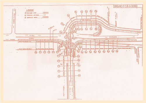
Figure: 1 Turbhe Flyover at Navi Mumbai
In addition, there are 4 Nos. simply supported spans (spans varying between 38.50 m to 45.50 m) of cast-in-situ, PSC single cell box girder type superstructure; across the railway tracks.
The flyover has the following 4 arms in the via-duct portions.
Mumbai–Thane Arm —
8 Nos spans of 7 m carriageway widths on Thane side
Mumbai–Panvel Arm—
10 Nos. spans of 11 m on Panvel side and 8 (4 + 4) Nos spans of total 14 m carriageway width on Mumbai side.
Thane–Mumbai Arm—
10 Nos. spans of 7 m carriageway width on
Thane side
Panvel–Mumbai Arm—
11 Nos. spans of 11 m carriageway width on Panvel side and 8 (4 + 4) Nos spans of total 14 m carriageway width on Mumbai side.
From the sections of box girders, it is apparent that two types of RCC box girders of 7 m and 11 m carriageway widths have been used.
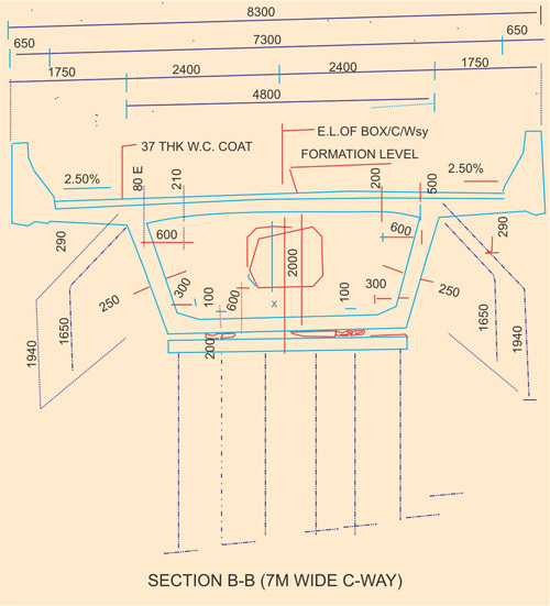
Figure 2: Section of box girder
The inclined webs of box girders are supporting the top deck slab with outer faces of webs as 6.10 m (with minimum web thickness as 300 mm and minimum deck slab thickness at centre as 230 mm) for 11.00 m wide carriageway and 4.80 m (with minimum web thickness as 250 mm and minimum deck slab thickness at centre as 200 mm) for 7.00 m wide carriageway.
It has been reported that the design was carried out as per relevant IRC and as per loading condition of bridges on National Highways and as per stipulations of contract agreement.
After construction the flyover was opened to traffic in November / December, 1994.
The traffic on all the arms of the flyover is very high, both in terms of volume and heavy vehicles with high axle loads, i.e. of the order of – PCU (Passenger Car Unit). In axle load survey on Mumbai - Nashik highway, it is seen that axle loads exceeding 20 t i.e., gross vehicle weight much higher than permitted by RTO regulation (two axle truck upto 26.0 t and six axle vehicle upto 116.0 t) are plying.
The flyover, in the viaduct portion, has 55 Nos. of simply supported spans (spans in the range of 30 m each) of cast-in-situ RCC, single cell box girder type superstructure, while the obligatory railway spans are with spans of cast-in-situ, prestressed single cell box girders.
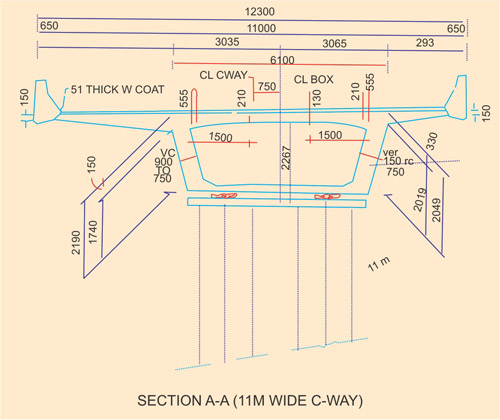
Figure 3: Sections of box girders
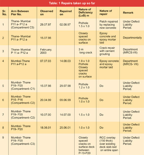
In July, 1997, a through-hole (pot hole) in deck slab at an isolated location was noticed. Though the pot hole was repaired, but every year one more pot hole started appearing in the deck slab of RCC box girders. Those pot holes were repaired, but lately more and more pot holes started appearing in different isolated locations of the deck slab. Repairs so far carried out have been listed in Table 1.
Field Observations
Concerned PWD officials showed the typical distressed / damaged locations and provided the past repair rehabilitation history of the flyover.The condition of the flyover with naked eye from a distance of 20' or so revealed, most of the deck slab's soffit contain isolated short length cracks of varying widths (approximately 0.1 mm to 0.2 mm), barring fewer ones exceeding 0.3 mm wide. Similar type of network spread of cracks is visible in the intermediate cross girders and in end diaphragms too.
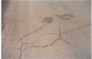
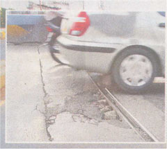
Photo 4
The major damage in the deck slab is noticeable in the suspended portion between two webs. In cantilever portion, as of today at least when observed with naked eye, there is no severe damage, although there are signs of minor distress.
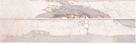
In Mumbai - Thane arm, in span P19 - P20, (where RCC overlay has been carried out in May, 2002) it is noticed top of deck slab, contains a few isolated short length cracks and in a local pocket of about 2.0 m x 2.0 m number of closely spaced cracks (Photo 5). It is informed the span with RCC overlay is functioning satisfactorily without any visual signs of increase in length or width of cracks.
In the complete length of flyover, there is no sign of corrosion of reinforcement.
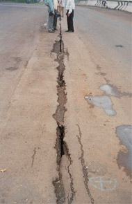
Photo 5
In addition, the following discrepancies were noticed.
- The slab-seal type expansion joints installed on the flyover reveal early signs of damage / deterioration and anchor bolts exposed at many locations and adjacent concrete band damaged.
- Across the obligatory railway spans, the gap between superstructures of two arms may cause a concern in near future.
Behavior of Repaired Surfaces
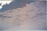
Photo 6
- The 150mm thick RCC overlay provided over entire deck of span between P19-P20 on Mumbai-Thane Arm taken up in May 2002 has behaved satisfactorily so far. A few short length isolated cracks on top of overlay apparently have not progressed in length or width. With similar progressive deterioration of deck slab in a balanced cantilever box girder repaired in the past, a thin RCC overlay (an overlay of 125mm thick M40 grade concrete with 0.6% isotropic reinforcement and with 15mm integral concrete wearing course in a clear gap of 2.38m between webs of box girders (where existing deck slab thickness of deck slab was 180mm) was installed in first quarter of 1989 in some other bridge. No further problem has been reported so far and the repaired portion has behaved satisfactorily. Similarly, in span between P19-P20 in Mumbai-Thane arm a RCC overlay of 150 thicknesses with 0.5% isotropic reinforcements was installed in May 2002. So far this is also performing satisfactorily without creation of any new pot hole in the span or without any major problem as on the overlay
- A few pot holes repaired by replacing the disintegrated concrete with new concrete of same grade performed satisfactorily under existing high volume of traffic mixed with regular heavier wheel loads.
- Where as a patch repair with epoxy injection to closely spaced cracks did not stop recurrence of new pot holes, Original deck below the area when inspected showed the process of formation of pot hole this shared with epoxy injection, the strength and integrity of concrete could not be restored.
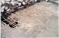
Photo 7
New cracks below the closely spaced cracks at top are indicative of inadequate repair of the deck slab before laying of overlay concrete.
Even in cracked area, the overlay concrete is performing its intended function.
Discussion on Field Observation
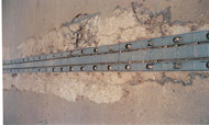
Photo 8
- When the first pot hole in the deck slab appeared in deck slab of span (between pier P11a to P12a) in Thane - Mumbai arm (on 29.07.1997), process of progressive permanent internal structural(micro cracking)change in the concrete subjected to fluctuating changes in stresses and strains was already set in
- As a result of progressive internal cracking, macro cracks grew below the bituminous wearing coat which went unnoticed and subsequently every year one more pot hole started appearing in isolated locations of other spans.
- Local patch repair by replacement of disintegrated concrete with new concrete of similar modulus of elasticity, performed well, but appearance of similar pot holes in other portions of deck slab did not stop.
- Lately, the rate of appearing pot holes has increased significantly, especially in the suspended span portion of the deck slab between the webs of the box girder and away from the haunched portion of the deck slab. In the common parlance, the recurrence of pot holes is seen preceded by widening and extension of the cracks in criss-cross direction, forming through cracks and allowing leakage of water, near disintegration of concrete in closely cracked areas, with growing appearance of cracks in asphalt wearing course with local depression in wearing surface and finally forming through hole (pot hole) in the deck slab and wearing course.
- Presently, there are many such locations at various stages of formation of pot holes.
- The results of inspection of January to March, 2003 revealed that cracks at deck soffit are generally of small lengths and width mostly between 0.1 mm to 0.2 mm while a few ones reached to 0.3 mm and a very small number reached to 0.4 mm. Cracks of non progressive nature upto width 0.3 mm may be acceptable in RCC structures subject to static load unless those are in aggressive environment exposure.
- The cracks noticed on intermediate cross-girders are of short length of width between 0.1 mm to 0.2 mm while a small number of cracks reached upto 0.3 mm width and a very few reached to 0.4 mm width. Many of these cracks have been repaired by sealing and grouting with epoxy material. It would be important to note that the cracks in intermediate cross-girders and end diaphragms did not progress with time or additional cracks did not appear after the earlier cracks were repaired.
- There are diagonal and vertical cracks on both inclined faces of web of box girders. It is reported cracks from inside are repaired by sealing and grouting with epoxy. Though the outside cracks were not repaired, there is no sign of pressure injected epoxy flown along coming out from outside, which shows that the cracks are not through. No cracks are noticed after inside cracks were sealed. There are transverse cracks at soffit of bottom slab of box girders. Since fully filled with dust and dirt inside the cracks from inside cracks in the bottom of slab are not visible.
- The outer faces of box girders are provided with protective epoxy coating. There is no corrosion stain marks visible in any area.
- In the reinforcements exposed in pot holes, there is no sign of rusting of reinforcements. From these, it can be concluded that the concrete is without any effect of aggressive salt or chemicals which can start corrosion of reinforcements or deteriorate concrete.
- At many locations where depression and cracks in wearing course are noticed, there are reports of water leakage through deck slab which indicate formation/development of cracks below wearing course.
- There is no sign of deterioration of concrete in any other parts of the flyover.
- 87 mm thick wearing course, consisting of 25mm thick Asphaltic Concrete, 50mm thick Bituminous Macadam and 12mm thick Mastic Asphalt is provided over the deck slab. Except where, the wearing course is damaged due to formation of pot holes and disintegration of deck concrete has taken place, the wearing surface is fairly smooth without much of undulations.
- Change in the longitudinal profile of the box girders, could not be observed since no data from strain gauges or deflectometer was available and as such the deck slabs cannot be considered to be performing satisfactorily as per design under global condition, but have been under progressive deterioration, and these slabs are proving to be inadequate under the action of local wheel load with short fatigue life.
Inference
Photo 9
- The concrete in thin deck slab is non-uniform both in design terms of quality and cover to reinforcements.
- Heavy wheel loads (In excess of the design permitted), generate severe concentrated local stressing particularly in the longitudinal distribution steel (provided on percentage basis of transverse steel) & this can develop excessive stresses under individual wheel loads. The situation can be aggravated by bigger concrete cover to reinforcements. In such a situation widening of transverse cracks both at top and soffit of deck slab cannot be ruled out.
The plying of loads heavier than design permitted over thin slab develop higher stresses and strains at soffit of deck slab which attribute to the widening of longitudinal cracks. - The fine cracks in the soffit of deck slab have occurred, as a result of not that of drying shrinkage or variation in temperature gradient but definitely due to increase in fatigue load.
- Repeated number of one way vehicles create higher stresses and strains when compared to the normal two way bridges and flyovers with similar type of severe load intensity (as could be).
- Once the crack has appeared, there are instantaneous widening and closing of the crack with every passage of heavier wheel loads. This tends to increase the crack in length and width. In this process, the transverse and longitudinal cracks join and develop a mesh pattern of cracks at the soffit of the deck. Further the transverse cracks at deck top developed due to high longitudinal moment due to heavy concentrated wheel load join the soffit crack. Once the crack passage is through rainwater starts trickling through crack passage and wash away, dislodged fine particles from the cracks cement paste aiding widening and propagation of crack in the process. Needless to mention that this process continues with the repeated passage of heavy wheel loads. With spider net (criss-cross) cracks and a few visible through cracks, signifying that the integrity of concrete in flexural behavior is almost lost and the concrete gets fully disintegrated.
In extreme cases, it is found that portion of the deck slab with such criss-cross wide cracks deflect visibly under wheel load and in some cases spalling of concrete at the top of deck slab is seen to have commenced. Such weak spots and spalling of top concrete are reflected in the form of closely spaced cracks and small depressions in the wearing course surface. With further passage of vehicles the disintegrated concrete starts getting dislodged from the reinforcements and a through hole (pot like hole) gets formed in the deck slab. This progressive deterioration of concrete under the repeated action of heavy wheel loads is comparable to fatigue failure of concrete. The fatigue behavior in such reinforced concrete bridge deck structure is more pronounced as the dead load stress in such deck structure is very small while the fluctuations in stress level due to heavier moving wheel loads are very high and with repetition with every passage of vehicle. This fatigue failure of concrete is further accelerated by passage of rain water through the cracks. - Absence of cracks or any other forms of distress in the cantilever portion and haunched portion of deck slab is indicative that those are not affected by heavier wheel loads or fatigue phenomenon.
- The cracks on the webs of box girders are not apparently through type and do not show any signs of increase/decrease in length and width. Apparently these cracks are not influenced by heavier and repeated vehicle loads.
- The transverse cracks visible at the soffit of bottom slab of box girders also do not show any signs of increase/decrease in length and width. Apparently these cracks are also not affected by heavier and repeated vehicle loads.
- Similar type of fatigue failures have been reported in bridges in Japan and investigated by taking deck panels from distressed bridges and tested in the laboratory by simulating repeated wheel load condition, including the effect of wetting/dying (due to rainfall). The investigation showed the fatigue failure of concrete under the action of repeated wheel and accelerated failure due to rain water passing through the deteriorated deck.
From the foregoing, it is evident that the problem is with the suspended span portion of deck slab where, in localised pockets progressive and extension of cracks lead to disintegration of concrete. The phenomenon is progressing with time. The minor cracks existing at the soffit of the deck slab are acceptable in RCC structure, but for those which do not give any prior indication of formation of pot holes in future.
From this, one may conclude that in this particular flyover with loads very heavy than permitted, the effect of fatigue is having a significant effect in progressive deterioration of concrete.
Rehabilitation Measures
Since distress in the flyover superstructure in the form of micro cracking of matrix of concrete is the progressive one in isolated pockets rehabilitation of the deck slab is essential. The following steps need to be implemented:- Potential repair of the existing deck slab surface to restore the riding surface and integrity to its design level
- Local repair for strengthening of the deck slab to lengthen the fatigue life and resist the local action of repetitive wheel loads.
a) Local Repair of Deck Surface
Steps to be taken:- Mapping of cracks at soffit of deck slab from inside the box girder. Mark all visible cracks (cracks upto 0.1mm width). Closely spaced cracks and cracks in criss-cross pattern of width more than 0.3mm shall be marked as potential area of start of the process of disintegration of concrete which might form pot hole in future. By sounding with a hammer the soft patches and the concrete in the process of disintegration can be identified.
While mapping of deck soffit, other cracks (0.3mm or of more width) in webs of girders, intermediate cross girders and end diaphragms shall be noted. - Total removal of Asphaltic wearing course and air blowing to remove loose particles. Tar or Asphaltic material, if any, remaining after removal of Asphaltic wearing course by chipping off, shall be carefully scrapped off and cleaned.
- Marking deficient areas of deck slab along with cracks at top of deck. Dismantling deteriorated concrete of identified pockets in a planned manner without disturbing the existing reinforcements. Re concreting of the removed portion with M-40 grade concrete with suitable anti-shrinkage admixture. Sealing of cracks at both soffit and top of deck with polymer modified cement mortar. Injection of epoxy based compound through cracks from underside of deck slab. Rendering of bad patches of concrete and honeycombs, if any, with cement mortar (1:3) and finishing with polymer modified cement mortar. The bonding between old and new concrete/mortar shall be with polymer cement slurry. All such repair work may be possible with partial closure of traffic. The traffic, however, has to be keep at low speed and if possible closed to trucks and heavy vehicles.
b) Strengthening or shielding the deck slab
Strengthening of deck slab is considered in many ways however the following methods may be tried:- Steel I-beams are placed longitudinally below the deck slab and supported on intermediate cross-girders and end diaphragms. The longitudinal I-girders will reduce the span to 1/3 of the present span in the transverse direction i.e. 1.425m (for box girder with 7m wide carriageway) and 1.825m (for box girder with 11m wide carriageway). This can reduce the transverse bending moment considerably. The negative transverse bending moment created over the new supports, are expected to be small and within the capacity of the existing section. The gap between existing concrete faces and new steel parts, have to be appropriately packed for proper functioning of the additional support.
All steel sections required for the purpose shall have to be brought inside the box girders through the manhole in the soffit slab of the box girder and further moved forward through the openings in the intermediate cross-girders and end diaphragms. Due to limited depth inside the box the length of steel sections which can be taken inside the box would be limited. Appropriate splice jointing of sections to make the full length has to be taken up inside the box girders. All these will not only put some constraints but also appropriate strict control would be necessary for ensuring quality.
The efficiency of the system will depend to what extent an appropriately designed and fabricated steel structure can be installed and integrated into the system and to what extent this will reduce the fatigue in concrete under such repeated heavy wheel loads. In case of doubt, this can be further enhanced by additional shielding with RCC overlay at top. - Stitching of Steel strips
Steel strips are placed below the deck slab parallel to the main steel of the deck slab to reduce the stresses in steel by considerable amount. These steel strips will be of mild steel and will be fixed with expansion anchor bolts to the deck slab in addition to epoxy bonding. The idea of providing these steel strips is that as they are effective only for the live loads, the stresses in concrete and steel due to live load are expected to reduce significantly. Consequently, the strains in concrete would be reduced and the probability of crack formation would be eliminated.
These steel strips, however, will not increase the strength of the deck slab in the longitudinal direction. Therefore, even after providing steel strips transverse cracks can still appear in between the steel strips. With such possibility in view, the deck slabs may have to be further strengthened by additional shielding with RCC overlay at top. - Shielding the deck slab in the form of RCC over lay
The purpose of this overlay is to relieve the existing deck slab from the local action of the wheel load, while the repaired deck will perform primarily the global function of the box section. Integrating the overlay with the existing deck slab with shear connectors or relaying on the bond at the interface by providing epoxy bonding compound is not considered appropriate due to the deteriorated condition of the existing deck slab. Effective bonding can only be relied upon the cantilever portion of the deck slab, over the web portion of the box girder and over the haunched portion of the deck slab which are not cracked and have not suffered any apparent distress. In order to minimize over stressing of the box girders under global action, a thin overlay is required to be designed by in-elastic method. Such empirical design is covered in Section 7.4 of Ontario Highway Bridge Design Code. This, however, has to fulfill a few design conditions. With the basic presumption that edge stiffening provided by integrating the overlay along the edges (carriageway end curbs/crash barriers and effective epoxy bonding between the deck and overlay in cantilever portion of deck slab, top portion of webs of box and haunched portion of deck slab) is effective, a thin overlay can be designed to carry the local action of wheel load independent of the existing deck slab. As this overlay would be supported by the existing deck slab, for any non-uniformity in construction of the overlay slab, the existing deck slab will provide the local support. The load transmitted to the repaired deck slab would be much less firstly due to independent behavior of the overlay slab and partly due to dispersal of the load in a much bigger area creating very small moments and stresses in the existing deck slab. Keeping these in view, the thin RCC overlays have to be designed meeting the design conditions of Ontario Code as much as possible and by extrapolation where necessary. The existing clear gap between inner faces of the webs of the boxes with 7.0 m and 11.0 m wide carriageways are 4.3m and 5.5m respectively. Considering the span of the slab as between centre of haunches, the spans can be assumed as 3.70 m and 4.30 m for 7.00 m and 11.00 m wide carriage-ways respectively. The Clause 7.4 of Ontario Code generally limits the span of slab as 3.70 m while the charts are upto 4.50m. Accordingly, 150mm and 200mm thick M40 concrete overlays with 0.6% orthotropic reinforcements are proposed for box girders of 7.00m and 11.00m wide carriageways respectively. Additional 10mm thickness of concrete at top is proposed to be provided as integral wearing course. Alternately, a new wearing course of 40-50mm thickness with ACC Marg can be provided over the overlay. This additional load of RCC overlays with additional wearing course will marginally increase (About 11%) the stresses in concrete and steel of box girders. Considering the increase in allowable stresses indicated in IRC SP-37 this marginal increase in allowable stresses may be considered as not significant and can be allowed.
Considering, the field constraints along with relative ease and economy of construction between different alternatives, the following method of strengthening/shielding of the existing deck slab is recommended.
- After completion of steps (i) through (iii) in (a) Local Repair of Deck Slab, the work of RCC overlay has to be taken up. The thickness of RCC overlay would be 160mm and 210mm for 7.00m and 11.00m wide carriageways respectively. The grade of concrete of overlay shall be M40 and reinforcements shall be 0.6% isotropic type (reinforcement of 0.6% of cross-sectional area shall be in both direction in both top and bottom).
- Before placement of new concrete over the existing deck slab, the deck top surface shall be thoroughly cleaned of all loose particles, sticking bitumen, oil, grease, paints, etc. The surface may be roughened by minor chipping for ensuring better interface friction between deck and overlay concrete. The reinforcements shall be placed continuous with staggered lapping of reinforcements with appropriate cover to reinforcements. Immediately before placing of fresh concrete of overlay, the existing deck top shall be coated with appropriate epoxy bonding compound. The concrete shall be laid while the epoxy bonding compound is still tacky. The concrete shall be properly vibrated and compacted to the specified thickness and slope and with rough finish at top. The concrete shall be cured by covering with wet hessian cloth and regular sprinkling of water and depending on type of cement used curing shall start early to avoid plastic shrinkage cracks.
- After the traffic is allowed over the repaired spans of the flyover, the performance of the repair work shall be monitored on regular basis. The top of overlay shall be checked for appearance of cracks and local depression, if any. The survey from the top may be taken up on half yearly basis. The soffit of the deck shall also be inspected on a yearly basis for appearance of cracks, seepage of water or any other forms of distress. Cracks not widening or extending in time can be sealed with polymer modified mortar. If the deck soffit is showing any sign of extending and widening of cracks, those cracks, in addition to sealing, will need further grouting with epoxy based material. Inspite of this sealing and grouting, in the unlikely event of new cracks still start appearing then the deck slab has to be considered for further strengthening by introduction of steel girder supports. This strengthening, however, can be taken up from inside the box and without disturbing the traffic.
- The expansion joints have to be installed at the new deck level (after laying of overlay and wearing course). The existing slab seal type expansion joints are partly damaged and might further get damaged in removal and reinstallation. Considering the limited life of the existing expansion joints, it may be prudent to install new expansion joints of strip seal type. These new joints shall be placed after re-concreting as per requirement of the supplier of new expansion joints.
- Miscellaneous repair of longitudinal joints between two adjacent superstructures shall be re-concreted along with overlay concrete and wearing course at top. Such joints shall have angle iron sections anchored along edges and appropriate drip course below. The gap between edges shall be maintained as 20mm without any continuity between adjacent spans. Other minor repairs of damaged or defective components (Say non functioning drainage spouts etc) noticed, if any, shall be repaired and reinstalled.
Conclusion
The deck slabs of RCC box girders in the suspended portion are seen to be affected by progressive deterioration due to repeated passage of heavy wheel loads. This phenomenon which can be compared with fatigue in concrete deck structures in bridges of RCC superstructures are being noticed in many bridges in India and abroad. This progressive deterioration of concrete with final visible manifestation in the form of formation of through holes (pot holes) are more common in bridges where the traffic is high in terms of volume and heavier wheel loads. As per conventional methods of analysis (statical analysis), these bridge decks are capable of carrying those heavier wheel loads, but the present IRC codes and other International codes are not appropriately giving guidance on how to take care the effects of repeated wheel loads. Research works throughout the world are in progress to establish the exact source of the problem and for possible solution to the problem. The repair and rehabilitation already carried out in the country, in similar distressed slab with additional RCC overlay designed on the basis of empirical method of Ontario Code has shown some initial promise of trouble free performance in future. Accordingly, for rehabilitation of this flyover, in addition to repair of the distressed deck slabs, an RCC overlay is proposed over the existing deck slab. The increase in stress level due to this additional concrete overlay is minor to affect the overall performance of the superstructure. Once executed with the requisite quality control, this will eliminate progressive deterioration of concrete even with repeated passage of heavy wheel loads. In such a distressed and repaired bridge, irrespective of the method of repair, it would be essential that for assessment of durability and long time performance of the flyover, the monitoring and maintenance inspection is taken up on regular basis. The inspection can identify progressive deterioration, if any, and can set the course of all future maintenance repair work necessary for ensuring durability and trouble free service life of the flyover.Acknowledgment
Author is grateful to the officers of PWD and Consultants who provided the details of site information.References
- Okada, K. Okamura H. and Sonoda K., Fatigue failure mechanism of reinforced concrete bridge deck slabs, Transp. Res. Rec. No.664, 1978, pp. 136-144.
- ACI Committee 215, Considerations for design of concrete structure subjected to fatigue loading, J. Am. Conc. Inst., Proc., Vol. 71, No.3, March 1974, pp. 97-121.
- Lenschow R., Fatigue of concrete structures, Proc. Int. Ass. Bridge Struct. Eng. colloq, Lausanne, 1982, IABSE Rep., Vol. 37, pp 15-24.
- Shah, S. P. and Chandra, S., Critical stress, volume change and micro-cracking of concrete, J. Am. Conccr. Inst... Proc., Vol 65 No.9 Sept 1968 pp. 770-781.
- Shah, S. P. and Chandra. S., Fracture of concrete subjected to cyclic and sustained loading, J. Am. Concr. Inst., Proc., VoI. 67, No.10, Oct. 1970, pp. 816-824.
- Holmen, J. 0., Fatigue of concrete by constant and variable amplitude loading, Recent research in fatigue of concrete structures, American Concrete Institute, SP-75, 1982, pp. 72-110.
- Oplc, F. S. and Hulsobs, C. L., Probable fatigue life of plain concrete with stress gradient, J. Am. Concr. Inst., Proc., Vol. 63. No.1, Jan. 1966, pp. 59-81.
- Nordby, G. M., A review of research-fatigue of concrete, J. Am. Concr. Inst., Proc., Vol. 55. No. 2, Aug. 1958, pp. 191-220
- Hilsdorf, H. K., and Kesler, C. E., Fatigue strength of concrete under varying flexural stresses, J. Am. Concr. Inst., Proc. VoI 63. No.10, Oct. 1966. pp. 1069-1076.
- Miner, M. A., Cumulative damage in fatigue Trans. Am. Soc. Mech. Eng., Vol. 67, 1945, pp A159-164
- American Association of State Highway and Transportation Officials, Standard specifications for highway bridges, 12th Edn. 1977, Washington. DC. 496 pp.
- Highway Research Board, AASHTO road test, Report 4, bridge research, Special Report 61D, Publication No.953, National Academy of Sciences. National Research Council, Washington. DC, 1962, 217 pp.
- Suryawanshi C S (Dr) 1995: Rehabilitation of Structures in Bombay: Ph.D. Thesis submitted to University of Amravati (Maharashtra), India.
Published on:
15 September 2010
Published in: NBM&CW October 2010
Share:
We Value Your Comment