Mix Design for Pumped Concrete with PPC, OPC, OPC+Flyash
A simple method of concrete mix design for pumpable concrete based on an estimated weight of the concrete per unit volume is presented in the article. The Tables and Figures included are worked out by the author from a wide range of materials available in the country. The method is suitable for normal weight concrete and with admixtures.
Kaushal Kishore, Materials Engineer, Roorkee, Uttaranchal
Pumped Concrete
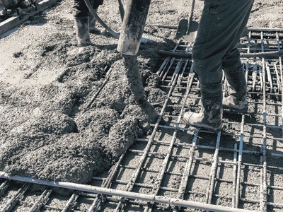
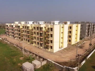
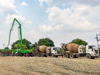
Pumped concrete may be defined as concrete that is conveyed under pressure through either rigid pipe or flexible hose and discharged directly into the desired location. Pumping may be used for most all concrete construction, but is especially useful where space or access for construction equipment is limited.Pumping equipment consists of pumps which are of three types:
- Piston type concrete pump
- Pneumatic type concrete pump
- Squeeze pressure type concrete pump
A pumpable concrete, like conventional concrete mixes, requires good quality control, i.e. properly graded uniform aggregates, materials uniformly and consistently batched and mixed thoroughly. Depending on the equipment, pumping rates may vary from 8 to 130 m3 of concrete per hour. Effective pumping range varies from 90 to 400 meters horizontally, or 30 to 100 meters vertically. Cases have been documented in which concrete has successfully been pumped horizontally upto 1400 meters and 430 meters vertically upward. New record values continued to be reported.
Pumping
For the successful pumping of concrete through a pipeline, it is essential that the pressure in the pipeline is transmitted through the concrete via the water in the mix and not via the aggregate; in effect, this ensures the pipeline is lubricated. If pressure is applied via the aggregate, it is highly likely that the aggregate particles will compact together and against the inside surface of the pipe to form a blockage; the force required to move concrete under these conditions is several hundred times that required for a lubricated mix.If, however, pressure is to be applied via the water, then it is important that the water is not blown through the solid constituents of the mix; experience shows that water is relatively easily pushed through particles larger than about 600 microns in diameter and is substantially held by particles smaller than this.
In the same way, the mixture of cement, water and very fine aggregate particles should not be blown through the voids in the coarse aggregate. This can be achieved by ensuring that the aggregate grading does not have a complete absence of material in two consecutive sieve sizes – for example, between 10 mm and 2.36 mm. In effect any size of particle must act as a filter to prevent excessive movement of the next smaller size of material.
Basic Considerations
Cement Content
Concretes without admixtures and of high cement content, (over about 460 kg/m3) are liable to prove difficult to pump, because of high friction between the concrete and the pipeline. Cement contents below 270 to 320 kg/m3 depending upon the proportion of the aggregate may also prove difficult to pump because of segregation within the pipe line.
Workability
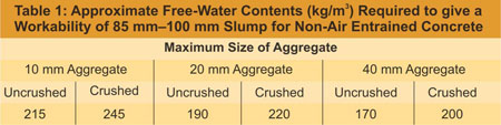
The workability of pumped concrete in general has an average slump of between 50 mm and 100 mm. A concrete of less than 50 mm slump is impractical for pumping, and slump above 125 mm should be avoided. In mixtures with high slump, the aggregate will segregate from the mortar and paste and may cause blocking in the pump lines.The mixing water requirements vary for different maximum sizes and type of aggregates. The approximate quantity of water for a slump of 85 mm and 100 mm is given in Table 1. In high strength concrete due to lower water/cement ratio and high cement content, workability is reduced with the given quantity of water per cu.m. of concrete. In such cases, water reducing admixtures are useful. In the addition to this type of admixtures at normal dosage levels, to obtain a higher workability for a given concrete mix, there is no necessity to make any alteration to the mix design from that produced for the concrete of the initial lower slump. There is generally no loss of cohesion or excess bleeding even when the hydroxycarboxylic acid baset materials are used.
If this class of product is used to decrease the water/cement ratio, again no change in mix design will be required, although small alterations in plastic and hardened density will be apparent and should be used in any yield calculations.
A loss of slump during pumping is normal and should be taken into consideration when proportioning the concrete mixes. A slump loss of 25 mm per 300 meters of conduit length is not unusual, the amount depending upon ambient temperature, length of line, pressure used to move the concrete, moisture content of aggregates at the time of mixing, truck-haulage distance, whether mix is kept agitated during haulage etc. The loss is greater for hose than for pipe, and is sometimes as high as 20 mm per 30 meter.
Aggregates
The maximum size of crushed aggregate is limited to one-third of the smallest inside diameter of the hose or pipe based on simple geometry of cubical shape aggregates. For uncrushed (rounded) aggregates, the maximum size should be limited to 40% of the pipe or hose diameter.The shape of the coarse aggregate, whether crushed or uncrushed has an influence on the mix proportions, although both shapes can be pumped satisfactorily. The crushed pieces have a larger surface area per unit volume as compared to uncrushed pieces and thus require relatively more mortar to coat the surface. Coarse aggregate of a very bad particle shape should be avoided.
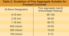
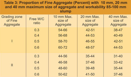
Fine aggregate of Zone II as per IS: 383-1970 is generally suitable for pumped concrete provided 15 to 30% sand should pass the 300 micron sieve and 5 to 10 percent should pass the 150 micron sieve. Fine aggregate of grading as given in Table 2 is best for pumped concrete. The proportion of fine aggregate (sand) to be taken in the mix design is given in Table 3. However, the lowest practical sand content should be established by actual trial mixes and performance runs.
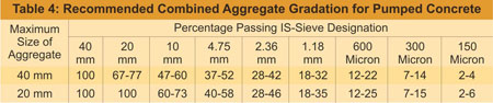
In practice, it is difficult to get fine and coarse aggregates of a particular grading. In the absence of fine aggregate of required grading they should be blended with selected sands to produce desired grading, and then combined with coarse aggregates to get a typed grading as per Table 4.
Uncrushed Aggregate (River Gravel)
It has become a custom that almost in all the construction sites crushed aggregates are being used. To save environmental pollution as far as possible in ordinary construction works uncrushed aggregates (River Gravel) including river sand should be used.Production of crushed aggregates from crushers poses air and noise pollution problems.
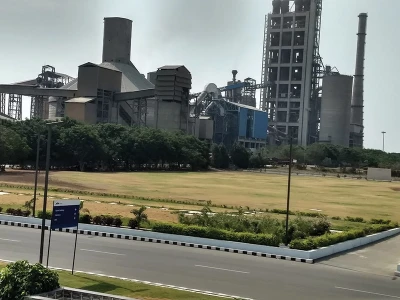
Crusher & Air Pollution Problem
When the rocks and river bed boulders are crushed, dry surfaces are exposed and air borne dust can be created. An inventory of sources of dust emissions usually begins with the first crusher and continues with the conveyor transfer points to and including the succeeding crushers. Here the aggregate is more finely grounded, and dust emission become greater. As the process continues, dust emission are again prevalent from sources at conveyor transfer points and the final screens.In the modern screening and washing plant in the production of uncrushed (gravel/shingle) aggregate from the river bed they are not crushed, thus no dust is formed. Further aggregates are washed to remove silt and clay like materials. Therefore, uncrushed (gravel/shingle) aggregates produces in these plant arrive at site in a moist condition, hence do not present a dust problem. Whereas the crushed aggregate leave crushing plant very dry and create considerable dust when handled. To prevent dust in handling it is not possible to wet each load of crushed aggregate thoroughly before it is dumped from the delivery truck. Attempts to spray the crushed aggregate as it is being dumped have had very limited effectiveness.
During crushing of aggregate particles less than 100 micron remains suspended in the air. The suspension of a particle in the air follows a certain trajectory depending on its size, density, shape and other physical properties. In air turbulence the dry crusher dust has long trajectories or suspension time and settling distance to the ground. If a crushing plant is not properly designed and operate without any efficient prevention system this “fugitive” dust may generate air pollution.
Note:
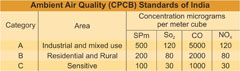
- SPm : Suspended particle matters
SO2 : Sulpher dioxide
CO : Carbon Mono oxide
NOx : Nitrogen Oxide - The concentrations for the above pollutants shall be 95% of the time within the limits prescribed.
- Category ‘C’ sensitive areas are: Hill Stations, Tourist Resorts, Sanctuaries, National Part, National Manuments etc.
- The air quality levels should be determined by sampling and brought down within specified ambient air quality standards through use of various mitigation measures, modern pollution free equipment and advance construction technology, such as giving preference in using uncrushed (gravel/shingle) natural aggregate in the general civil engineering construction work in place of crushed aggregate obtained from crusher.
Pumping
Before the pumping of concrete is started, the conduit should be primed by pumping a batch of mortar through the line to lubricate it. A rule of thumb is to pump 25 litres of mortar for each 15 meter length of 100 mm diameter hose, using smaller amounts for smaller sizes of hose or pipe. Dump concrete into the pump-loading chamber, pump at slow speed until concrete comes out at the end of the discharge hose, and then speed up to normal pumping speed. Once pumping has started, it should not be interrupted (if at all possible) as concrete standing idle in the line is liable to cause a plug. Of greater importance is to always ensure some concrete in the pump receiving hopper at all times during operation, which makes necessary the careful dispatching and spacing of ready-mix truck.Testing for Pumpability: There is no recognized laboratory apparatus or precise piece of equipment available to test the pumpability of a mix in the laboratory. The pumpability of the mix therefore, should be checked at site under field conditions.
Field Practices: The pump should be as near the placing area as practicable and the entire surrounding area must have adequate bearing strength to support the concrete delivery trucks, thus assuring a continuous supply of concrete. Lines from the pump to the placing area should be laid out with a minimum of bends. For large placing areas, alternate lines should be installed for rapid connection when required.
When pumping downward 15 m or more, it is desirable to provide an air release valve at the middle of the top bend to prevent vacuum or air buildup. When pumping upward, it is desirable to have a valve near the pump to prevent the reverse flow of concrete during the fitting of clean up equipment, or when working on the pump.
Illustration example on Concrete Mix Design.

Test Data for Materials
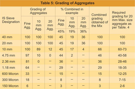
- The grading of fine aggregate, 10 & 20 mm aggregates are as given in Table. 5. Fine aggregate is of zone-I of IS:383-1970. 10 and 20 mm crushed aggregate grading are single sized as per IS: 383-1970.
- Properties of aggregates
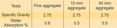
- Target strength for all A, B and C mixes
fck = fck + 1.65 x S40 + 1.65 x 5
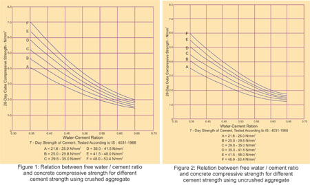
= 48.3 n/mm2 at 28 days age - For Mix A and B free W/C ratio with crushed aggregate and given strength for target strength of 48.3 n/mm2 at 28 days from Fig. 1 Curve D found to be 0.40. This is lower than specified maximum W/C ration value of 0.45
Note: In absence of cement strength, but cement conforming to IS Codes, assume from Fig. 1 and Fig. 2.
Curve A and B for OPC 33 Grade
Curve C and D for OPC 43 Grade
Curve E and F for OPC 53 Grade
Take curves C and D for PPC, as PPC is being manufactured in minimum of 43 Grade of strength. - Other data: The Mixes are to be designed on the basis of saturated and surface dry aggregates. At the time of concreting, moisture content of site aggregates are to be determined. If it carries surface moisture this is to be deducted from the mixing water and if it is dry add in mixing water the quantity of water required for absorption. The weight of aggregates are also adjusted accordingly.
Design of Mix-a with PPC
- Free W/C ratio for the target strength of 48.3 n/mm2 from Fig. 1 curve D found to be 0.4
- Free water for 100 mm slump from Table 1 for 20 mm maximum size of aggregate.
From trials, it is found that Retarder Superplasticizer at a dosages of 18 gm/kg of cement water may be reduced 25% without loss of workability
Then water = 200 – (200 x 0.25) = 150 kg/m3 - PPC = 150/0.4 = 375 kg/m3
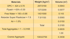
- Formula for calculation of fresh concrete weight in kg/m3
UM 10 x Ga (100 – A) + CM(1 – Ga/Gc) – WM (Ga – 1)
Where,
Um = Wight of fresh concrete kg/m3
Ga = Weighted average specific gravity of combined fine and coarse aggregate bulk, SSD
Gc = Specific gravity of cement. Determine actual value, in absence assume 3.15 for OPC and 3.00 for PPC (Fly ash based)
A = Air content, percent. Assume entrapped air 1% for 40 mm maximum size of aggregate, 1.5% for 20 mm maximum size of aggregate and 2.5% for 10mm maximum size of aggregate. There are always entrapped air in concrete. Therefore, ignoring entrapped air value as NIL will lead the calculation of higher value of density.
Wm = Mixing water required in kg/m3
Cm = Cement required, kg/m3
Note:- The exact density may be obtained by filling and fully compacting constant volume suitable metal container from the trial batches of calculated design mixes. The mix be altered with the actual obtained density of the mix.
Um = 10 x Ga (100 – A) + Cm (1 – Ga/Gc) – Wm (Ga – 1)
= 10 x 2.75 (100 – 1.5) + 375(1- 2.75/3.00) – 150 (2.75 -1)
Density = 2477 kg/m3 - aggregates = 2477 – 375 – 150 = 1952 kg/m3
- Fine aggregate = From Table 3 for zone-I Fine aggregate and 20 mm maximum size of aggregate, W/C ratio = 0.4 found to be 44 – 53%. For consideration of grading of Table 4 let it be 45% Fine aggregate = 1952 x 0.45 = 878 kg/m3 Coarse aggregate = 1952 – 878 = 1074 kg/m3
10 and 20 mm aggregate are single sized as per IS: 383-1970. Let they be combined in the ratio of 1:2
10 mm aggregate = 358 kg/m3
20 mm aggregate = 716 kg/m3
With the consideration of grading of Table 5 let Fine aggregate, 10 and 20 mm aggregate combine in the ratio of 45%, 19% and 36% and check with the required grading of Table. 5.
Thus,
Fine aggregate = 878 kg/m3
10 mm = 1952 x 0.19 = 371 kg/m3
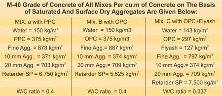
20 mm = 1952 x 0.36 = 703 kg/m3 - Thus for M-40 Grade of concrete quantity of materials per cu.m. of concrete on the basis of saturated and surface dry aggregates:
Water = 150 kg/m3
PPC = 375 kg/m3
Fine Aggregate (sand) = 878 kg/m3
10 mm Aggregate = 371 kg/m3
20 mm Aggregate = 703 kg/m3
Retarder Super Plasticizer = 6.75 kg/m3
Mix-B with OPC
- Water = 200 – (200 x 0.25) = 150 kg/m3
- OPC = 150/0.4 = 375 kg/m3
- Density:
10 x 2.75 (100 – 1.5) + 375 (1 – 2.75/3.15) – 150 (2.75 – 1)
= 2495 kg/m3 - Total Aggregates = 2495 – 150 – 375 = 1970 kg/m3
Fine Aggregate = 1970 x 0.45 = 887 kg/m3
10 mm Aggregate = 1970 x 0.19 = 374 kg/m3
20 mm Aggregate = 1970 x 0.36 = 709 kg/m3 - Thus for M-40 Grade of concrete with OPC per cu.m of concrete on the basis of saturated and surface dry aggregates.
Water = 150 kg/m3
OPC = 375 kg/m3
Fine Aggregate (sand) = 887 kg/m3
10 mm Aggregate = 374 kg/m3
20 mm Aggregate = 709 kg/m3
Retarder Super Plasticizer = 5.625 kg/m3
Mix. C with OPC + Flyash
Total cementitious materials = 375 x 1.13 = 424 kg
Note:-
- Specific gravity of Retarder Superplasticizer = 1.15
- Addition of Flyash reduces 5% of water demand.
- For exact W/C ratio the water in admixture should also be taken into account.
- The W/C ratio of PPC and OPC is taken the same assuming that the strength properties of both are the same. If it is found that the PPC is giving the low strength then W/C ratio of PPC have to be reduced, which will increase the cement content. For getting early strength and in cold climate the W/C ratio of PPC shall also be required to be reduced.
- PPC reduces 5% water demand. If this is found by trial then take reduce water for calculation.
Conclusion
Pumped concrete may be used for most/all concrete construction, but is especially useful where space or access for construction equipment is limited.Although the ingredients of mixes placed by pump are the same as those placed by other methods, quality control, batching, mixing, equipment and the services of personnel with knowledge and experience are essential for successful pumped concrete.
The properties of the fine normal weight aggregates (sand) play a more prominent role in the proportioning of pumpable mixes than do those of the coarse aggregates. Sands having a fineness modulus between 2.4 and 3.0 are generally satisfactory provided that the percentage passing the 300 and 150 micron sieves meet the previously stated requirements. Zone-II sand as per IS: 383-1970 meets these requirements, and is suitable for pumped concrete.
For pumped concrete, there should be no compromise in quality. A high level of quality control for assurance of uniformity must be maintained.
A simple method of concrete mix design with normal weight aggregates and with admixtures for pumped concrete is described in the article. The author has worked out the Tables and Figures for materials available in the country by numerous trials. Therefore, the proportions worked out with the help of these Tables and Figures will have quite near approach to the mix design problems in the field.
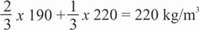
Note:- When coarse and fine aggregate of different types are used, the free-water content is estimated by the expression,

Where, Wf = Free-water content appropriate to type of fine aggregate.
and, Wc= Free-water content appropriate to type of coarse aggregate.
Note:- The above combined obtained grading is for PPC and OPC mixes. For OPC + Flyash Mix fine aggregate is about 43%, 10 mm 20% and 20 mm is 37%. This is also within the permissible limits of recommended grading for pumped concrete.
References:
- IS : 383-1970 Specifications for coarse and fine aggregates from natural sources for concrete (second revision) BIS, New Delhi
- IS: 456-2000 Code of practice for plain and reinforced concrete (fourth revision), BIS, New Delhi
- IS: 9103-1999 Specification for admixtures for concrete (first revision) BIS, New Delhi
- IS: 8112-1989 Specifications for 43 Grade ordinary portland cement (first revision) BIS, New Delhi
- IS: 2386 (Part-III) 1963 method of test for aggregate for concrete. Specific gravity, density, voids, absorption and bulking, BIS, New Delhi
- IS: 3812 (Part-I) 2003 Specification for pulverized fuel ash: Part-I for use as pozzolana in cement, cement mortar and concrete (second revision) BIS, New Delhi
- IS: 1489-Part-I 1991 Specifications for portland pozzolana cement (Part-I) Flyash based. (Third revision), BIS, New Delhi
- Kishore Kaushal, “Design of Concrete Mixes with High-Strength Ordinary Portland Cement.” The Indian Concrete Journal, April, 1978, PP. 103-104
- Kishore Kaushal, “Concrete Mix Design.” A manual published for Structural Engineering Studies, Civil Engineering Department, University of Roorkee, 1986.
- Kishore Kaushal, “Concrete Mix Design Based on Flexural Strength for Air-Entrained Concrete,” Proceeding of 13th Conference on our World in Concrete and Structures, 25-26, August, 1988, Singapore.
- Kishore Kaushal, “Concrete Mix Design,” Indian Concrete Institute Bulletin September, 1988, pp. 27-40 and ICI Bulletin December, 1988, pp. 21-31.
- Kishore Kaushal, “Method of Concrete Mix Design Based on Flexural Strength,” Proceeding of the International Conference on Road and Road Transport Problems ICORT, 12-15 December, 1988, New Delhi, pp. 296-305.
- Kishore Kaushal, “Mix Design Based on Flexural Strength of Air-Entrained Concrete.” The Indian Concrete Journal, February, 1989, pp. 93-97.
- Kishore Kaushal, “Concrete Mix Design,” VIII All India Builders Convention 29-31, January, 1989, Hyderabad, organized by Builders Association of India, Proceeding Volume pp. 213-260.
- Kishore Kaushal, “Concrete Mix Design Containing Chemical Admixtures,” Journal of the National Building Organization, April, 1990, pp. 1-12.
- Kishore Kaushal, “Concrete Mix Design for Road Bridges,” INDIAN HIGHWAYS, Vol. 19, No. 11, November, 1991, pp. 31-37
- Kishore Kaushal, “A Concrete Design,” Indian Architect and Builder, August, 1991, pp. 54-56
- Kishore Kaushal, “Mix Design for Pumped Concrete,” Journal of Central Board of Irrigation and Power, Vol. 49, No.2, April, 1992, pp. 81-92
- Kishore Kaushal, “Concrete Mix Design with Fly Ash,” Indian Construction, January, 1995, pp. 16-17
- Kishore Kaushal, “High-Strength Concrete,” Civil Engineering and Construction Review, March, 1995, pp. 57-61.
- Kishore Kaushal, “High-Strength Concrete,” Bulletin of Indian Concrete Institute No. 51, April-June, 1995, pp. 29-31
- Kishore Kaushal, “Mix Design of Polymer-Modified Mortars and Concrete,” New Building Materials & Construction, January, 1996, pp. 19-23.
- Kishore Kaushal, “Concrete Mix Design Simplified,” Indian Concrete Institute Bulletin No. 56, July-September, 1996, pp. 25-30.
- Kishore Kaushal, “Concrete Mix Design”, A Manual Published by M/S Roffe Construction Chemicals Pvt. Ltd., Mumbai, pp. 1-36
- Kishore Kaushal, “Concrete Mix Design with Fly Ash & Superplasticizer,” ICI Bulletin No. 59, April-June 1997, pp. 29-30
- Kishore Kaushal. “Mix Design for Pumped Concrete,” CE & CR October, 2006, pp. 44-50.
Published on:
14 September 2010
Published in: NBM&CW September 2010
Share:
We Value Your Comment