Applications of High Performance Concrete in Hydropower Structures
Jitendra Thakur, Dy. Chief Engineer, Jaypee (Hydro Div.); Noida
General
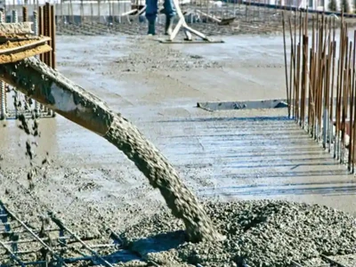
Hydropower Structures are constructed to tap the untamed water resources and generate useful Electrical Energy for the benefit of mankind. The quantity of concrete consumed in making various components of hydropower structures is enormous. A few of its components viz. glacis of Spillway, Diversion Tunnel, Head Race Tunnel, Silt Flushing Tunnel, Tail race Tunnels etc. are required to be lined/coated with High Performance Concrete so that their performance in handling high velocities of water and huge quantities of silt is enhanced. The use of High Performance concrete has resulted into lesser repairs, on one hand, and increased durability, on the other hand.
High Performance Concrete
The high Performance Concrete is defined as the concrete that cannot be made by conventional methods of manufacturing concrete. The Definition of High Performance Concrete, applicable to Hydropower Structures, may differ with that of the definition used for High Performance Concrete used for Infrastructure say Bridges wherein High Performance Concrete is required for Early High Strength, greater span, reduced depths of members etc. but in case of Hydropower Structures, High Performance Concrete is required basically to have higher resistance against abrasive, erosive and cavitational action of moving water. Structures are lined/coated with High Performance Concrete to enhance their performance.
During sixties Dams were built in Masonary. The structures were bulky and were lesser stressed. A few exmples are Nagarjuna Sagar Dam (Andhra Pradesh), Krishnaraja Sagar Dam (KN) Gandhi Sagar Dam (MP) Jawai Dam (RJ). They were built in Masonary and are performing nicely. The openings (gates) to allow flood to pass were greater in number and velocities at spillway were lesser.
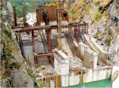
With more innovation in the field of materials and equally more understanding of loads, the factor of safety kept for the uncertainties is decreasing. Today, the gate sizes are bigger than yester years, less in numbers; tunnels are smaller in size, resulting into increased values of stresses. The construction time is also reducing and putting more pressure on quality aspects of the construction. A few recently completed schemes are Karcham HEP (1000 MW), Tala HEP (1020MW), Baghlihar HEP(450MW) etc.
Concrete is becoming more like scientific material rather than the material which Sir John Smeaton had developed in 1756 by adding pebbles as a coarse aggregates and brick powder into cement. This was later modified by Sir Joseph Aspdin in 1824, who created Cement by burning ground limestone and clay together.
Today's concrete, with the help of innovative peripherals, has developed following capacities:
(i) it can remain in liquid state for a longer duration,
(ii) it can be prepared with very small quantity of water, and
(iii) it can also gulp waste materials having pozzalanic reactivity like flyash, Ground Granulated Blast furnace Slag, Silica fume, Rice Husk ash etc. to give itself strength and increased life.
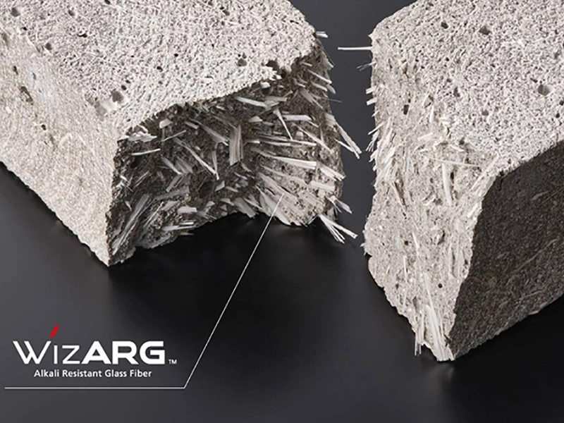
The addition of mineral admixtures, while manufacturing concrete, tends to densify the transition zone between aggregates and matrix in the structure of the concrete. This makes the transition zone more stronger and more energy is required to break the transition zone, which generally is weakest zone and responsible for failure of concrete. Thus, the resistance against abrasion increases. Addition of Mineral Admixture, lesser quantity of water and optimum quantity of super-plasticizer makes concrete more durable as compared to conventional concrete.
 |
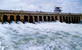 |
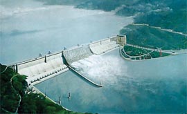
| Three Gorges Dam (China – 2009) built on River Yangtze | Krishnaraja Sagar Dam (Karnataka - 1924) built on river Kaveri |
During sixties Dams were built in Masonary. The structures were bulky and were lesser stressed. A few exmples are Nagarjuna Sagar Dam (Andhra Pradesh), Krishnaraja Sagar Dam (KN) Gandhi Sagar Dam (MP) Jawai Dam (RJ). They were built in Masonary and are performing nicely. The openings (gates) to allow flood to pass were greater in number and velocities at spillway were lesser.
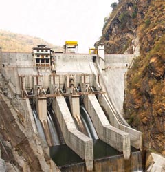 |
| Tata HEP (Bhutan – 2007) built on river Wangchu |
Concrete is becoming more like scientific material rather than the material which Sir John Smeaton had developed in 1756 by adding pebbles as a coarse aggregates and brick powder into cement. This was later modified by Sir Joseph Aspdin in 1824, who created Cement by burning ground limestone and clay together.
Today's concrete, with the help of innovative peripherals, has developed following capacities:
(i) it can remain in liquid state for a longer duration,
(ii) it can be prepared with very small quantity of water, and
(iii) it can also gulp waste materials having pozzalanic reactivity like flyash, Ground Granulated Blast furnace Slag, Silica fume, Rice Husk ash etc. to give itself strength and increased life.
The addition of mineral admixtures, while manufacturing concrete, tends to densify the transition zone between aggregates and matrix in the structure of the concrete. This makes the transition zone more stronger and more energy is required to break the transition zone, which generally is weakest zone and responsible for failure of concrete. Thus, the resistance against abrasion increases. Addition of Mineral Admixture, lesser quantity of water and optimum quantity of super-plasticizer makes concrete more durable as compared to conventional concrete.
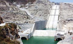
Spillway Structure
The flood water is allowed to pass the Dam through its spillway. The quantum of Discharge depends upon Probable Maximum Flood to be passed. The velocity of water passing at this structure is quite high. The Glacis of Spillway tends to bear velocities to the tune of 25 to 60m/s. This structure is most vulnerable from erosion point of view. Considerable damage to stilling basin is generally caused by eddy currents coupled with high velocity flow and impact due to debris. The galcis, stilling basin, bucket etc. suffer huge damages when flood is allowed to pass through it.
Tehri Spillway Structure
 |
| Three Gorges Dam (China – 2009) built on River Yangtze |
The prime aim of designing concrete of glacis is to have lower loss of material against erosive action of water laden with heavy silts. High Performance Concrete (HPC) is considered necessary for guarding against cavitations damages and for taking care of possible damages due to abrasion. It was found that the increase in quantity of mineral admixture ie. Microsilica along with other aspects of Mix Design, the resistance against abrasion improved considerably from 1.33% for M30 to 0.94% for M70. The mix proportion adopted is given in Table 1:
| Table 1 : Concrete Mixes for Tehri Dam Project | ||||
| Mix Ingredients | Recommended Grades of concrete and Quality of Mix Ingredients in kg/m3 | |||
| M30 | M50 | M60 | M70 | |
| Jaypee Cement | 317 | 340 | 365 | 380 |
| Microsilica | 34 | 37 | 38 | |
| CA-1 ( 20mm) | 684 | 696 | 687 | 680 |
| CA-2 ( 10mm) | 456 | 464 | 458 | 454 |
| FA-1 ( Crushed stones) | 266 | 271 | 268 | 265 |
| FA-2 ( Natural sand) | 494 | 503 | 496 | 491 |
| Water | 143 | 142 | 140 | 142 |
| Superplasticizer (% of binder) | 1 | 2 | 2 | 1.75 |
| W/B ratio | 0.38 | 0.35 | 0.34 | |
| W/c ratio | 0.45 | 0.42 | 0.38 | 0.37 |
| Initial slump | 175 | 180 | 230 | 185 |
| Slump after 45 min. | 120 | 110 | 160 | 120 |
| Compressive strength results | ||||
| 3 days | 20.89 | 29.33 | 43.29 | 51.16 |
| 7 days | 28.13 | 43.82 | 56.49 | 60.85 |
| 28 days | 35.73 | 56.18 | 68.23 | 75.4 |
| abrasion loss after 72 hr (%) | ||||
| High speed (3360 rpm) | 6.26 | 3.06 | 2.88 | 2.75 |
| slow speed (1100 rpm) | 1.33 | 1.1 | 1.05 | 0.94 |
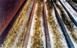
Chukha Spillway Structure
Chukha HEP is 336 MW Project and is located in Bhutan. In this Project, M20A20 grade concrete was used alongwith rails in spillway and the project was commissioned during 1986. The erosion of concrete between rails was found to vary from 10mm to 150mm. Repairs of spillway glacis were thereafter carried out by filling the cavities on top layer of concrete with High performance concrete and was found to perform satisfactorily.
 |
 |
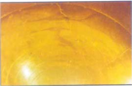
| Damages Observed in Spillway | Damages Observed in Stilling Basin |
Kinzua Dam Stilling Basin, USA
Damages to stilling basins have occurred even in advanced countries. Typical amongst these is the stilling basin of Kinzua Dam on the Allegheny River in Western Pennsylvania (USA). It was put to operation initially in 1967, but experienced severe abrasion /erosion damages. The basin was repaired in 1973-74 using steel fiber reinforced concrete overlay. Deterioration continued to the extent that repairs were again necessary in 1983. Thereafter, repairs were carried out with high performance concrete made with micro silica.
The performance of this reconstruction work has been regularly inspected. Previous repairs using conventional concrete had a life far less than one year, the micro silica concrete exhibited very little wear (Table 2).
The performance of this reconstruction work has been regularly inspected. Previous repairs using conventional concrete had a life far less than one year, the micro silica concrete exhibited very little wear (Table 2).
| Table 2 : | |
| Mix Ingredients | |
| Cement, Type I/Il | 386 kg/m3 |
| Silica Fume Slurry (46% dry powder) | 156 |
| Water | 80 |
| Silica fume | 70 |
| Admixtures | 6 |
| Coarse Aggregate,19 mm, | SSD 971 |
| Fine Aggregate, | SSD 824 |
| Water (added as batch water) | 50 |
| w/cm | 0.28 |
| Fresh Properties | |
| Average air Content: | 3.2 % |
| Average slump: | 250 mm |
| Average unit weight: | 2444 kg/m3 |
| Silica fume by cement mass: | 18% |
| Core compressive strength | |
| 7 days, 28 days, 90 days test results from Contractor | 72.9, 89.1, 107.0 |
| 28 days, 90 days test results from Owner | 94.6, 103.2 |
Tala Dam
 |
| Tala HEP- Spillway Glacis |
Power Intake
Intake is the first structure of the water conductor system. The water passes from Intake to HRT and thereafter to the Power House for the generation of Electricity. The velocity at this structure is about 4-5 m/s along with some silt. The silt gets flushed in the Desilting Chamber before entering into HRT.
Tala Power Intake
The ternary system has been used in producing M30 A40 grade pumpable concrete for use in transition portion from rectangular to horse shoe shape in intake structure. The mix proportion adopted is given in Table 4.
By adding about 7-8% micro silica, abrasion resistance of concrete is improved. The micro silica in concrete is being used mainly for improving abrasion resistance of concrete. In intake structure, the micro silica is used in M30 A40 grade concrete for 5m transition portion from rectangular to horseshoe shape, down stream of service gate. As this portion of concrete structure is likely to be subjected to higher abrasive forces due to high velocity of water, use of micro silica was considered necessary. The pumped concrete with a slump of about 150 mm was produced using 7.5 % micro silica by weight of cement (PSC).
By adding about 7-8% micro silica, abrasion resistance of concrete is improved. The micro silica in concrete is being used mainly for improving abrasion resistance of concrete. In intake structure, the micro silica is used in M30 A40 grade concrete for 5m transition portion from rectangular to horseshoe shape, down stream of service gate. As this portion of concrete structure is likely to be subjected to higher abrasive forces due to high velocity of water, use of micro silica was considered necessary. The pumped concrete with a slump of about 150 mm was produced using 7.5 % micro silica by weight of cement (PSC).
| Table 3 : Concrete Mixes for Tala Dam Project | ||||
| Mix Ingredients | Recommended Grades of concrete and Quality of Mix Ingredients in kg/m3 | |||
| M30 | M50 | M60 | M70 | |
| Slag Cement | 460 | 400 | 400 | 400 |
| Silicafume | 0 | 40 | 40 | 40 |
| CA-1 ( 20mm) | 693 | 788 | 830 | 830 |
| CA-2 ( 10mm) | 520 | 544 | 564 | 577 |
| FA (River sand) | 520 | 544 | 475 | 520 |
| Water | 207 | 150 | 135 | 108 |
| Superplasticizer (% of binder) | 0 | 1.75 | 1.25 | 1.95 |
| W/B ratio | 0.45 | 0.34 | 0.3 | 0.245 |
| Compressive strength results | ||||
| 3 days | 17.78 | 27.07 | 42.13 | 43.82 |
| 7 days | 26.0 | 48.04 | 56.31 | 62.58 |
| 28 days | 38.33 | 59.74 | 69.23 | 78.18 |
| Abrasion loss after 72 hr | 6.71 | 3.76 | 3.30 | 2.84 |
| Water Permeability (depth of Penetration) | 90 | nil | nil | Nil |
| Chloride Permeability RCPT (Coloumbs) | 2635 | 237 | 173 | 125 |
| Table 4 : Concrete Mix design for Power Intake | ||||||||
| Ingredients | Cement | Microsilica | FA | CA 40mm | CA 20mm | CA 10mm | Water | Superplaticizer |
| Quantity (kg/m3) | 400 | 30 | 587 | 620 | 334 | 238 | 175 | 6.02 |
Head Race Tunnel
Head race Tunnel is one of the key elements in deciding the cost of a Hydropower Scheme. The smaller is the diameter of Head Race Tunnel, the economical is the project. The length of HRT is generally in kilometers. The Tala HRT is 23 km long. Karcham HRT is 17.2 km long. As the diameter of the HRT is decreased, the velocity of flow increases, resulting into erosion and cavitation problems. It becomes utmost important to control the quality of HRT lining so that repairs are less and performance is better.
 |
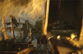 |
| Damages observed in Head Race Tunnel | Damages observed in Diversion Tunnel |
Tala Head Race Tunnel
Tala HRT is 6.8m in diameter and is 23km long. The concrete mix design of M20A20 grade was used in HRT lining. The mix was designed initially with a cement content of 375 kg/m3 (OPC) and was further revised with a cement content of 350 kg/m3 (OPC) in addition to micro silica content of 25 kg/m3. However, due to extensive cracking in concrete lining and alkali silica reactive aggregates with OPC, use of PSC without microsilica was resorted to. The cement content in concrete lining was optimised to avoid cracking in concrete due to heat of hydration of cement. The mix design with different cement content by using OPC and PSC are given in Table 5:
Common cause of cracking in concrete is due to restrained drying shrinkage. It is caused by loss of moisture from the cement paste in the mix. Due to excessive overbreaks, tensile stresses are caused by differential shrinkage between the surface and the interior concrete. The large shrinkage causes cracks at the surface and then it penetrates deeper into the concrete with time. Cracks are also caused by differential thermal stresses. It was found that addition of microsilica does not help every time. Ground Granulated slag was found to perform better in this case.
| Table 5 : Mix design of M20A20 grade concrete for HRT lining | ||||||||
| Sr. No. | Cement Content (kg/m3) | Type of Cement | Water | FA | 20 mm CA | 10 mm CA | Superplaticizer (kg/m3) | Remark |
| 1 | 375 | OPC-43G | 184 | 779 | 599 | 400 | 4.5 | Kerb, overt & Invert stage II |
| 2 | 350+25MS | OPC-43G | 190 | 702 | 637 | 425 | 5.63 | Kerb, overt & Invert stage II |
| 3 | 350 | PSC | 178.5 | 727 | 654 | 436 | 5.25 | Kerb, overt & Invert stage II |
| 4 | 340 | PSC | 170 | 703 | 459 | 408 | 4.08 | Invert stage I |
| 5 | 380 | PSC | 190 | 746 | - | 990 | 6.08 | Overt |
| 6 | 300 | PSC | 156 | 778 | 433 | 420 | 4.20 | Invert stage I |
| 7 | 325 | PSC | 169 | 791 | 677 | 437 | 4.55 | Kerb, overt & Invert stage II |
Common cause of cracking in concrete is due to restrained drying shrinkage. It is caused by loss of moisture from the cement paste in the mix. Due to excessive overbreaks, tensile stresses are caused by differential shrinkage between the surface and the interior concrete. The large shrinkage causes cracks at the surface and then it penetrates deeper into the concrete with time. Cracks are also caused by differential thermal stresses. It was found that addition of microsilica does not help every time. Ground Granulated slag was found to perform better in this case.
Diversion Tunnel
Diversion Tunnel is one of the initial structures constructed at the Hydropower Power Dam site. The non-monsoon flood is diverted through this structure so as to enable the construction of Main Dam. The erosion problems of Diversion Tunnel are similar to the Head Race Tunnel. Huge damages are observed at the DT when non-monsoon flood is passed through it. Use of High Performance concrete tends to improve performance of these structures, but due to excessive heavy sized of boulders and silt etc., damages are generally observed in this structure.
Conclusion
With increasing innovation in materials and mechanization, the civil engineering structures, in general and hydropower structures, in particular, are becoming more durable and thereby less repairs are required to be carried out. Better results shall be expected with the understanding of the behaviour of High Performance Concrete by people engaged in its manufacturing, placing and finishing.
Curing shall have to be more scientific and rigorous. In case of hot climates, curing shall start immediately after placing High Performance concrete. Firstly, by fogging and thereafter by wetting. As high performance concrete has virtually no water available for bleeding. Any delay in curing shall have permanent damage to the concrete, resulting into decreased line and becoming vulnerable as far as durability aspects are concerned. In case of cold climates, loss of heat from the body of concrete shall be protected by applying insulation like plastic sheets, thermocol etc. With improved site procedures, the site test results shall approach more towards laboratory results and therefore, concrete shall have both strength (to resist loads) and stamina (to fight with the distress).
Curing shall have to be more scientific and rigorous. In case of hot climates, curing shall start immediately after placing High Performance concrete. Firstly, by fogging and thereafter by wetting. As high performance concrete has virtually no water available for bleeding. Any delay in curing shall have permanent damage to the concrete, resulting into decreased line and becoming vulnerable as far as durability aspects are concerned. In case of cold climates, loss of heat from the body of concrete shall be protected by applying insulation like plastic sheets, thermocol etc. With improved site procedures, the site test results shall approach more towards laboratory results and therefore, concrete shall have both strength (to resist loads) and stamina (to fight with the distress).
References
- Relevant Websites
- Papers of various authors published in International Conference on 'Accelerated Construction of Hydropower Structures' held in Bhutan
Published on:
13 August 2012
Published in: NBM&CW August 2012
Share:
We Value Your Comment