Non destructive testing for determining the strength of concrete
Dr. Sanjeev Kumar Verma, Professor and Head, Department of Civil Engg., TIT, Bhopal
Civil engineering infrastructures are designed to operate for long periods of time, such as 50 to 100 years. However, several unpredictable and uncontrollable factors reduce their expected performance and life cycle. Lack of performance of these systems may significantly impact a nation’s economy. Hence, regular in-situ inspection of structures is required for assessing its condition. Monitoring and evaluating compressive strength of deteriorating structures is required for tracking the condition. Here, in this paper two most significant non destructive testing (NDT) methods for determining strength of concrete were discussed. Henceforth, an experimental study performed in Bhopal for determining relation between results of these tests and crushing strength of concrete has been presented.
Introduction
Compressive strength is the capacity of a material or structure to withstand loads tending to reduce size. It can be measured by plotting applied force against deformation in a testing machine. Some materials fracture at their compressive strength limit; others deform irreversibly, so a given amount of deformation may be considered as the limit for compressive load. Compressive strength is a key value for design of structures. There are two methods for finding compressive strength of concrete - Destructive testing method and Non-destructive testing method. The standard method of evaluating the quality of concrete in buildings or structures is to test specimens cast simultaneously for compressive, flexural and tensile strengths (Feldman, 1977) [1]. As the name suggests, destructive testing (DT) includes methods where your material is broken down in order to determine mechanical properties, such as strength, toughness and hardness. However, NDT are performed in a manner that does not affect the future usefulness of the reinforced concrete (RC) structures.
Non-destructive testing can be applied to both old and new structures. For new structures, the principal applications are likely to be for quality control or the resolution of doubts about the quality of materials or construction. The testing of existing structures is usually related to an assessment of structural integrity or adequacy. In either case, if destructive testing alone is used, for instance, by removing cores for compression testing, the cost of coring and testing may only allow a relatively small number of tests to be carried out on a large structure which may be misleading. The process of SHM involves monitoring a structure over a period of time using appropriate sensors, extracting damage sensitive features from the measurements given by the sensors, and analyzing these features to determine the current state of the structure.
Objective and scope of present work
- To study most significant NDT methods for determining the strength of concrete – Rebound hammer and Ultrasonic pulse velocity. To collect and study relevant literature for performing above studies.
- This study provides useful data regarding structural health monitoring for the new researchers and engineers interested in this topic.
- Presents a relation for evaluating the strength of concrete based on the results of NDT survey.
Several researchers applied NDT for evaluating strength and condition for RC structures. Refurbishment design of existing structures as well as to the design of new structures has been related using probabilistic modelling Grosso. (2013) [2]. Sanayei et al. (2012) [3] performed static truck load test on a newly constructed bridge, to capture the response of bridge when a truck travelled across it.
Amini and Tehrani (2011) [4] applied experimentally four sets of exposure conditions, weight and compressive strength of the samples had been measured before and after the freeze thaw cycles, and the results were analyzed. Ultrasonic guided waves have been utilized by Sharma and Mukherje in 2011 [5] for monitoring progression of rebar corrosion in chloride and oxide environment.
Wang and Liu (2010) [6] determined change in bond strength, loss of concrete cover in tensile zone and/or reduction of concrete cover in compressive zone as the major cause of deterioration of RC structures. Mitra et al. (2010) [7] discussed that repair and maintenance planning of concrete structures mainly depends on following conditions - rusting and cracking, delaminating, loss in steel section, workmanship, carbonation and chloride contents. Chen and Wimsatt (2010) [8] used 400MHzground-coupled penetrating radar (GCPR) to evaluate the subsurface conditions of roadway pavements. Terzic and Pavlovic (2010) [9] applied NDT methods that are Image Pro plus (IPP) and Ultrasonic Pulse Velocity (UPV), on the corundum and bauxite-based refractory concretes. Shah and Hirose (2010) [10] presented an experimental investigation of the concrete applying nonlinear ultrasonic testing technique. Bagchi et al. (2010) [11] applied cost effective and easy to implement, vibration-based damage identification (VBDI) techniques for Structural Health Monitoring of a bridge, based on changes in the dynamic characteristics of a structure to determine the location and extent of damage in the structure.
Ervin et al. (2009) [12] created an ultrasonic sensing network to assess reinforcement deterioration. Guided ultrasonic waves had been used to monitor reinforced mortar specimens under accelerated uniform and localized corrosion. Stergiopoulou et al. (2008) [13] presented a procedure for NDT of urban concrete infrastructures using UPV measurements and applied to assessment of concrete properties by concrete garages. UPV has been used as an indicator of concrete quality.
Rens and Kim (2007) [14] inspected a steel bridge using several NDT methods such as visual inspection, hammer sounding, Schmidt hammer, and UPV testing including tomography imaging; results of NDT had been used to determine areas, to be tested with local destructive tests such as compressive strength, chloride testing, and petro graphic testing. Dilek (2006) [15] discussed the use of pulse velocity, Young’s modulus of elasticity, and air permeability of concrete to evaluate the extent of damage of a concrete. Parthiban et al. (2006) [16] carried out potential surveys on the concrete structures. Among all electrochemical methods potential measurement is the mostly used field technique for detecting corrosion activity in steel.
Amleh and Mirza (2004) [17] performed concrete cover test, Half cell Potential, corrosion rate, electrical resistivity, chloride content at steel level (%), steel bar mass loss (%), absorption, pulse velocity, compressive strength, carbonation depth, petro graphic examination, and permeability test. Akuthota et al.(2004) [18] presented the experimental results of using near field microwave NDT techniques for detecting disbond in a specially prepared carbon fiber reinforced polymer (CFRP) reinforced mortar sample. Pascale et al. (2003) [19] carried out an experimental program involving both destructive and non destructive methods applied to different concrete mixtures, with cube strength varying from 30 to 150MPa, to define a relation between strength and parameters. Tests performed are pulse velocity, rebound hammer, pull out, and probe penetration, microcoring and combined methods.
Determination of compressive strength through NDT
Several methods are developed and reviewed by researchers to determine the compressive strength of concrete through NDT. Few methods are listed in table 1.
| Table 1 – NDT methods for determining compressive strength (Verma et al. 2013)[20] | |||
| NDT method | Advantages | Limitations | Principle |
| Rebound hammer | Simple, quick and inexpensive | Not so reliable, smoothness, age of concrete , carbonation, moisture contain can affect results | Rebound of plunger when strucked with concrete indicates strength |
|
Ultrasonic pulse velocity (UPV) |
quick, Portland, large penetration depth simple interpretation, and moderate cost |
not very reliable, moisture variation and presence of reinforcement can affect results | Ultrasonic wave velocity and its attenuation |
| Pull of test | Fast result, evaluate adhesion, and tensile strength which can be converted to compressive strength | Damage to the surface | A disc is bonded to the testing surface , and when disc is pulled off, force required is used to obtain pull of strength |
| CAPO TEST | Correlation between pull out force and compressive strength is relianble | Damage to the surface | Expanded ring in the cored hole is pulled out |
Rebound hammer and UPV are the two most significant methods for determining strength of concrete. These methods are described here-
Rebound hammer test
The rebound hammer test is basically a surface hardness test to find out the compressive strength of concrete by using rebound hammer as per the second part of IS 13311 (1992) [21] with little apparent theoretical relationship between the strength of concrete and the rebound number of the hammer. Rebound hammer test the surface hardness of concrete, which cannot be converted directly to compressive strength.
The Schmidt rebound hammer or rebound hammer is a simple and handy tool, which can be used to provide a convenient and rapid indication of the compressive strength of concrete. It consists of a spring controlled mass that slides on a plunger within a tubular housing. The Schmidt rebound hammer is shown in figure 1.
The rebound hammer method could be used for –
- Assessing the compressive strength of concrete with the help of suitable co-relations between rebound index and compressive strength.
- Assessing the uniformity of concrete.
- Assessing the quality of concrete in relation to standard requirements.
- Assessing the quality of one element of concrete in relation to another.
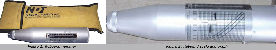
The compressive strength can be read directly from the graph having rebound number on the x-axis and compressive strength on the y-axis. The rebound scale and graph are graduated on the body of rebound hammer. The rebound scale and graph are shown in figure 2.
Ultrasonic Pulse Velocity Test
The UPV test is performed for strength determination of concrete, in accordance with IS 13311 (1991) [22]. It involves measuring the velocity of sound travelling through the concrete. Since, concrete is a multiphase material; velocity of sound in concrete depends on the relative concentration of its constituent materials, degree of compacting, moisture content and the amount of discontinuities present. This technique is applied for measurements of composition (e.g. to monitor the mixing materials during construction and to estimate the depth of damage caused by fire), strength estimation, homogeneity, elastic modulus and age, to check presence of defects, crack depth and thickness measurement. Generally, high pulse velocity readings in concrete are indicative of concrete of good quality. The drawback is that this test requires large and expensive transducers. In addition, ultrasonic waves cannot be induced at right angle to the surface. Hence, they cannot detect transverse cracks.
The ultrasonic pulse velocity method could be used to establish –
- The homogeneity of the concrete.
- The presence of cracks, voids and other imperfections.
- The change in structure of the concrete which may occur with time.
- The quality of concrete in relation to standard requirement.
- The quality of one element of concrete in relation to another.
- The values of dynamic elastic modulus of the concrete.
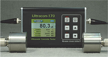
Figure 3: Apparatus for UPV
- Electrical pulse generator
- Transducer
- Amplifier
- Electronic timing device
| Table 2– Concrete quality for different values of UPV | |
| Pulse velocity (km/sec) | Concrete quality |
| >4.0 | Very good |
| 3.5 to 4.0 | Good, but may be porous |
| 3.0 and 3.5 | Poor |
| 2.5 and 3.0 | Very poor |
| 2.0 and 2.5 | Very poor and low integrity |
| 2.0 and reading fluctuating | No integrity, large voids suspected |
Results of experimental survey
Following steps are adopted for performing the required study –
15 cubes had been casted targeting different mean strengths. Further, the cubes were cured for different number of days to ensure availability of a wide range of compressive strength attained by these cubes. Size of each cube was 150×150×150 mm. then each is tested for rebound number, ultrasonic pulse velocity and crushing strength as per Indian codes. Table 3, presents the experimental data.
| Cube no. | Rebound Number (N) | Velocity (V) from UPV (m/s) | Crushing strength (f) of cube (Mpa) |
| 1 | 17 | 3660 | 13.0 |
| 2 | 17 | 3520 | 12.5 |
| 3 | 20 | 4120 | 14.6 |
| 4 | 21 | 4290 | 15.8 |
| 5 | 17 | 3580 | 12.7 |
| 6 | 18 | 3810 | 13.5 |
| 7 | 12 | 2590 | 9.2 |
| 8 | 13 | 2710 | 9.6 |
| 9 | 20 | 4150 | 14.7 |
| 10 | 22 | 4520 | 16.5 |
| 11 | 23 | 4570 | 17.6 |
| 12 | 17 | 3670 | 13.0 |
| 13 | 17 | 3530 | 12.5 |
| 14 | 16 | 3490 | 12.4 |
| 15 | 16 | 3320 | 11.8 |
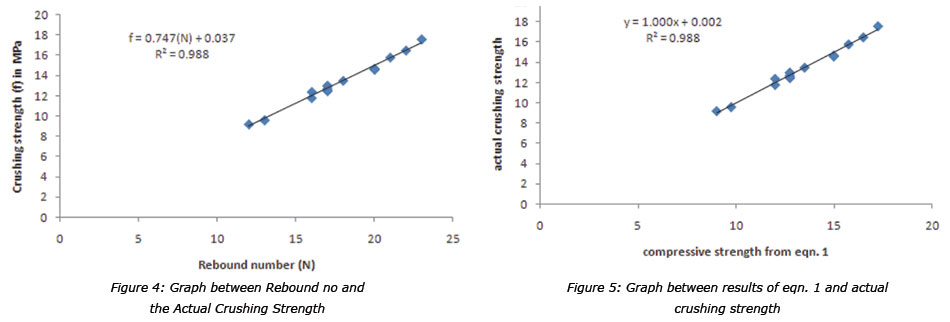
To determine the relation between rebound number and crushing a graph is plotted as shown in fig. 4 -
Relation obtained between the Rebound number (N) and the actual Crushing strength of concrete is shown in eqn. 1
f = 0.7475* (N) + 0.0376 ---(1)
To validate the above eqn. 1, values of compressive strength obtained from eqn. 1 were compared with values of actual crushing strength for each cube in fig. 5. It has been observed that results of eqn. 1 are almost similar to the actual crushing strength of concrete cubes.
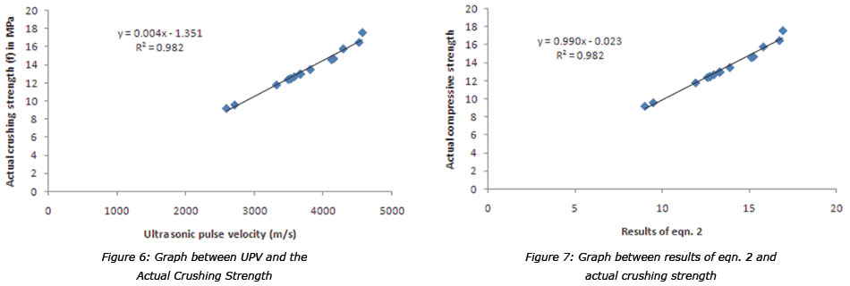
Similarly to obtain a relation for determining the compressive strength of concrete through UPV a graph shown in fig. 6 has been plotted between the Velocity (V) from UPV (m/s) and the Actual Compressive Strength (f) –
Relation obtained between the UPV (V) and the actual Crushing strength (f) of concrete is shown in eqn. 2
y = 0.004x - 1.3516 ---(2)
To validate the above eqn. 2, values of compressive strength obtained from eqn. 2 were compared with values of actual crushing strength for each cube in fig. 7. It has been observed that results of eqn. 1 are almost similar to the actual crushing strength of concrete cubes.
Conclusions
Following are the conclusions of the present research
- From literature review it has been concluded that Rebound hammer and Ultrasonic Pulse velocity are the most significant NDT methods for evaluating the strength of concrete.
- Relation between the Rebound Number and Actual Crushing strength of concrete structures is determined as - f = 0.7475 (N) + 0.0376 m, where ‘f’ is the compressive strength and N is the rebound number.
- Relation between the UPV and Actual Crushing strength of concrete structures is determined as - f =0 .004(V) -1.3516, where ‘f’ is the compressive strength and V is the velocity.
- Above relation are useful for the researchers interested in field of NDT.
- Feldman R.F. (1977), “Non Destructive Testing of Concrete”, Canadian Building Digest, C. U. Grosse, H. W. Reinhardt, and F. Finck, “Signal-based acoustic emission techniques in civil engineering,” Journal of Materials in Civil Engineering, vol. 15, no. 3, pp. 274–279, 2003.
- C. U. Grosse, H. W. Reinhardt, and F. Finck, “Signal-based acoustic emission techniques in civil engineering,” Journal of Materials in Civil Engineering, vol. 15, no. 3, pp. 274–279, 2003.
- M. Sanayei, J. E. Phelps, J. D. Sipple, E. S. Bell, and B. R.Brenner, “Instrumentation, non destructive testing, and finite element model updating for bridge evaluation using strain measurements,” Journal of Bridge Engineering, vol. 17, no. 1, pp.130–138, 2012.
- B. Amini and S. S. Tehrani, “Combined effects of saltwater and water flow on deterioration of concrete under freeze-thaw cycles,” Journal of Cold Region Engineering, vol. 25, no. 4, pp. 146–161, 2011.
- S. Sharma and A. Mukherje, “Monitoring corrosion in oxide and chloride envroments using ultrasonic guided waves,” Journal of Materials in Civil Engineering, vol. 23, no. 2, pp. 207–211, 2011.
- Wang, X., and Liu, X. (2010). “Simlified methodology for the evaluation of the residual strength of corroded reinforced concrete beams”. J. Perf. Constr. Fac., 24(2), 108-119.
- Mitra, G., Jain, K.K., and Bhattacharjee, B. (2010). “Condition assessment of corrosion-distressed reinforced concrete buildings using Fuzzy logic”. J. Perf. Constr. Fac., 24(6), 562-570.
- B. Chen, M. H. Maher, and E. G. Nawy, “Fibre optic brag grating sensor for nondestructive evaluation of composit beams,” Journal of Structural Engineering, vol. 120 no. 12, pp 3456–3469, 1995.
- A. M. Terzic and L. M. Pavlovic, “Application of results of non destructive testing methods in the investigation of microstructure of refractory voncretes,” Journal of Materials in Civil Engineering, vol. 22, no. 9, pp. 853–857, 2010.
- A. A. Shah and S. Hirose, “Nonlinear ultrasonic investigation of concrete damaged under uniaxial compression step loading,” Journal of Materials in Civil Engineering, vol. 22, no. 5, Article ID 007005QMT, pp. 476–483, 2010.
- A. Bagchi, J. Humar, H. Xu, and A. S. Noman, “Model-based damage identification in a continuous bridge using vibration data,” Journal of Performance of Constructed Facilities, vol. 24, no. 2, pp. 148–158, 2010.
- B. L. Ervin, D. A. Kuchama, J. T. Bernhard, and H. Reis, “Monitoring corrosion of rebar embedded in mortar using high frequency guided ultrasonic waves,” Journal of Engineering Mechanics, vol. 135, no. 1, pp. 9–18, 2009.
- C. Stergiopoulou, M. S. Aggour, and R. H. McCuen, “Nondestructive testing and evaluation of concrete parking garages,” Journal of Infrastructure Systems, vol. 14, no. 4, pp. 319–326, 2008.
- K. L. Rens and T. Kim, “Inspection of Quebec street bridge Denver, Colardo: destructive and nondestru testing,” Journal of Performance of Constructed Facilities, vol. 21, no. 3, pp. 215–224, 2007.
- U. Dilek, “Nondestructive and laboratory evaluation of damage gradients in concrete structure exposed to cryogenic temperatures,” Journal of Performance of Constructed Facilities, vol. 20, no. 1, pp. 37–44, 2006.
- T. Parthiban, R. Ravi, and G. T. Parthiban, “Potential monitoring system for corrosion of steel in concrete,” Advances in Engineering Software, vol. 37, no. 6, pp. 375–381, 2006.
- L. Amleh and M. S. Mirza, “Corrosion response of a decommissioned deteriorated bridge deck,” Journal of Performance of Constructed Facilities, vol. 18, no. 4, pp. 185–194, 2004.
- B. Akuthota, D. Hughes, R. Zoughi, J. Myers, and A. Nanni, “Near-field microwave detection of disbond in carbon fiber reinforced polymer composites used for strengthening cement-based structures and disbond repair verification,” Journal of Materials in Civil Engineering, vol. 16, no. 6, pp. 540–546, 2004.
- G. Pascale, A. D. Leo, and V. Bonora, “Nondestructive assessmen of the actual compressive strength of high-strengt concrete,” Journal of Materials in Civil Engineering, vol. 15, no 5, pp. 452–459, 2003.
- S. K. Verma, S. S. Bhadauria, and S. Akhtar, “Review of Nondestructive Testing Methods for Condition Monitoring of Concrete Structures,” Journal of Construction Engineering, vol. 2013, Article ID 834572, 11 pages, 2013. doi:10.1155/2013/834572
- IS: 13311 (Part 1): 1992 Non-Destructive Testing of Concrete-Method of Test; Part 1-Ultrasonic Pulse Velocity.
- IS: 13311 (Part 2): 1992 Non-Destructive Testing of Concrete-Method of Test; Part 2-Rebound Hammer.
Published on:
09 April 2018
Published in: NBM&CW March 2018
Share:
We Value Your Comment