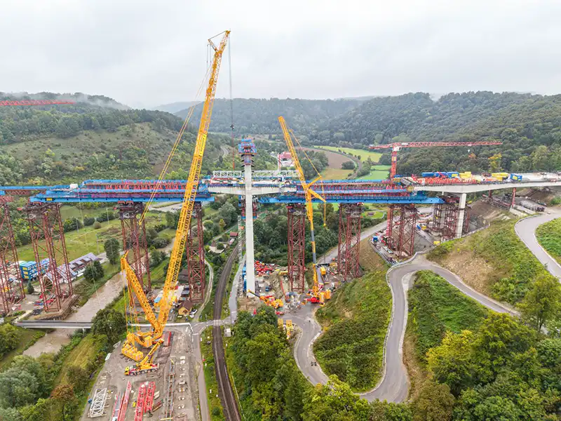
Two Liebherr cranes, an LR 1700-1.0 crawler crane and an LTM 1650-8.1 mobile crane from Wiesbauer GmbH & Co. KG, were deployed for the installation of solid steel plates beneath the bridge’s dual carriageway spans.
The lifts demanded exceptional precision and meticulous planning. The Horb Bridge is designed as an extra-dosed bridge, a modern hybrid between a cable-stayed and prestressed concrete structure, featuring low pylons and slender concrete footbridges that lend it a graceful aesthetic.
To ensure strength and durability, continuous steel plates, up to 14 cm thick and 157 metres long, are being installed under the carriageways. These plates are securely bonded to the concrete using thousands of headed dowel pins, allowing the structure to withstand high bending loads while maintaining its sleek design.
Heavy loads at lofty heights
Instead of welding the individual short plates onto the bridge - which would have blocked construction for weeks - they were welded into long steel plates on the ground in parallel with the other construction work, so that they could then be lifted as a whole. However, this increased the weight per element to up to 70 tonnes. To prevent the sheets from bending during lifting, they were attached to a lattice crossbeam. Including lifting gear, this resulted in loads of 85 and 102 tonnes, which had to be lifted from the valley onto the bridge being built at a height of 65 metres.
For this work, Wiesbauer used the LR 1700-1.0 with a 132 metre main boom, 12 metre fixed jib and up to 375 tonnes of ballast and the LTM 1650-8.1 with Y-guying, 155 tonnes of ballast, 16 metre telescopic extension and 38.5 metre luffing jib.
The LR 1700-1.0 was set up approximately in the centre of the valley directly in front of the bridge section where the heavier steel plates had to be mounted. This enabled the crane to cope with these loads on its own. For the positions further south, a tandem lift was necessary due to the larger radius, with the crawler crane working with the LTM 1650-8.1. The LR 1700-1.0 first placed the 85-tonne load in an accessible position on the bridge, from where the two cranes jointly slewed it to its final position and set it down with millimetre precision.
Precise technology and millimetre-precise coordination
The combination of VarioTray and V-Frame made the LR 1700-1.0 a decisive tool in the cramped operating conditions: the ballast radius could be continuously adjusted between 13 and 21 metres, depending on the radius. With a small radius, even the small pallet of the VarioTray with 100 tonnes of ballast was sufficient in some cases.
"Without VarioTray and V-Frame, the job would not have been possible in this form," explains crane operator Ralf Paladey. "During the lift, we had to constantly adjust the ballast radius in order to maintain the exact balance." The lift placed the highest demands on the control system and the interaction between the two machines. During the tandem lift, the working radius of the crawler crane reached up to 96 metres.
Cramped conditions and logistical challenges
The assembly of the cranes also required logistical finesse. The location was in a narrow valley - the Neckar to the north and a railway line to the south. An alternative set-up was ruled out. All the components had to be reloaded onto 8-axle low-loaders in order to safely negotiate the winding roads to the crane site in the valley. "Even the assembly was precision work," reports Ralf Hofmann, driver of the LTM 1650-8.1. "When installing the luffing jib, we had just one metre of space to the end of the path." Positioning closer to the bridge was impossible - the projecting edge only left about one metre of clearance at the lift.
Wiesbauer had calculated various options, including the use of a more powerful crawler crane. "Our LR 11000 could have handled the load from the stand alone," says project manager Jochen Wiesbauer, "but the ballast radius would have required slewing over the river - and that wasn't possible." A larger mobile crane was also considered, as the LTM 1650-8.1 was working at its limit. However, the dimensions of the 9-axle LTM 1750-9.1 did not allow it to travel down into the valley.
Planning with system and experience
The deployment was planned using the Liebherr tool LICCON deployment planner and a CAD system to precisely simulate all movements and loads. Nevertheless, some of the work was left to experience - especially when fine-tuning the cranes in tandem operation.
"Experience is essential here," emphasises crane operator Tim Moll. "Not everything can be calculated in advance. It is crucial to have the right sense of proportion when picking up the load and positioning the ballast pallet." After several days of intensive work, all four plates were securely mounted - a success that combined precision, technology and teamwork.