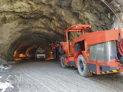
Tunnel Gantries: Fostering Safe, Efficient & Rapid Tunnel Construction

Naragana Jaya Chandra Gowd, Abhijeet Vijay Gawai, and Vivek Ganesh Abhyankar at SGAWings Consultants, Mumbai, share insights into Tunnel Gantries, their planning, design, construction, operation and maintenance strategies.
Tunnel gantries remain relatively understudied in academic literature
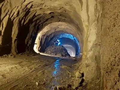
Photo Credit: Shram Engineering Works


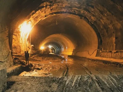
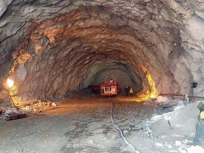
Tunnel gantries remain relatively understudied in academic literature, with limited research dedicated to exploring their design principles, operational characteristics (there are no specific design codes or books available exclusively for tunnel gantries). This paper delves into the historical background of tunnel gantries, elucidates their structural design and components, explores applications and uses of tunnel gantries, their advantages and disadvantages, examines the present studies and analyses technological innovations, highlights their implementation and impact. It discusses future trends and innovations, and addresses the gaps by providing a holistic understanding of tunnel gantries and their role in fostering safe, efficient, and rapid construction of tunnels.

Introduction

Historically, tunnelling primarily relied on manual labour using basic tools like pickaxes and shovels, resulting in a labour-intensive, slow, and hazardous process. The Industrial Revolution (AD.1760-1840) then introduced mechanised tunnelling, employing steam-powered machinery for excavation. By the mid-20th century, Tunnel Boring Machines (TBMs) emerged as an ingenious advancement, enabling faster and more efficient tunnelling, particularly in stable geological conditions. However, TBMs encountered difficulties in navigating complex (mixed) formations and lacked adaptability during construction, which demanded extensive planning and initial investments. In 1960s, the development of the New Austrian Tunnelling Method (NATM) offered a flexible approach emphasizing systematic excavation, immediate support, and continuous monitoring of ground behavior. NATM relies on the interaction between the ground and structure, with the surrounding rock or soil providing initial support until permanent linings are installed. Tunnel linings are the support system of a tunnel that strengthens their sides and roofs preventing them from collapsing. Tunnel linings can be of a simple shotcrete(ferrocement), RCC lining, steel ribs or prefabricated concrete segments.

Tunnel gantries remain relatively understudied in academic literature


The typical cross-section of the tunnel can be thought of as consisting of - curbs, inverts, curved walls, and roof arch. The sequence of constructing these components can be - curbs being initially, then inverts followed by walls, and finally the arch. However, in some cases inverts may be cast without curbs; or arches ahead of inverts. By utilizing tunnel gantries, construction crews can efficiently build tunnel lining (arches and walls) of varying shapes and sizes, tailored to the specific requirements of the tunnel design.

In modern transportation infrastructure, tunnel gantries are ‘fabricated structural steel frames’ that are used to support formwork for tunnel lining and various equipment and machinery. Intermediate platforms are provided in gantry for workers to access and work on elevated or hard-to-reach areas (usually 1.5m c/c).

Tunnel gantries are mostly used in NATM. During planning, designing, fabrication, quality control, transportation and installation, integrity with tunnel infrastructure, testing and commissioning at site, special care shall be taken. There are several types of tunnel gantries as per the requirement of the projects, namely- Horse Shoe Gantry, Modified Horseshoe Gantry, D type Gantry, Bellmouth gantry and also special gantries for various locations in the tunnel like Cavern Gantry, Pocket Gantry, T junction or Y junction Gantry etc. This paper covers various aspects of tunnel gantry design, including structural considerations, materials selection, components, integration with tunnel infrastructure and future scope. Also, the kinematics of tunnelling gantry movements is covered. A typical cross-section of a triple-track tunnel gantry is shown in graph 1.

Tunnel gantries remain relatively understudied in academic literature


Typical Components of Conventional Tunnel Gantry

‘A-Frame’ & Traveler Trolley (A Support System for tunnel formwork)

‘A-Frame’ is a supporting structure that forms the main framework of a gantry, providing stability and support for equipment, machinery, and formwork. It includes beams, trusses, or frames, engineered to withstand the loads encountered during tunnel construction. Figure (4) shows the front view of ‘A frame’ and it could be generally spaced at 3-12 meters c/c spacing along tunnel axis, connected by a traveler trolley. A traveller trolley is a frame that typically consists of sturdy beams or trusses designed to withstand the loads encountered during operation (figure 5). Movement of this assembly (A-frame & traveler trolley together) is controlled by operators using manual or automated mechanisms to drive the trolley along the tracks placed on the tunnel axis, allowing for precise positioning and smooth operation.

Tunnel gantries remain relatively understudied in academic literature


Gantry supporting formwork

Tunnel gantries are meant to support formwork, which shapes and holds fresh concrete during tunnel lining operation. Formwork can comprise of single module split into several smaller components (panels). It could be the assembly of a roof formwork panel for concrete lining of the arch portion & side formwork panel (as shown in fig.7 & 8) for lining of side walls of the tunnel. In some cases, if the cross section of tunnel is small in size, then invert formworks can be integrated with the main gantry. Panels are separated for easy assembly and transport, usually made of steel, timber, HDPE, or aluminium are assembled to create the desired tunnel cross-section. (But remember that life span of timber is lesser than steel; cost of aluminium is higher than steel; weight of HDPE is almost seven times lesser than steel but it is not weldable. This makes steel formwork more popular although susceptible to corrosion and heavy weight). Important characteristics of formwork and gantry is, it should be light in weight so that it can be lifted with minimum number of workers or forklifts inside the tunnel cavity. For a designed length of traveller trolley, concrete pouring work can be carried out in one go (generally 12m which is equal to length of one longitudinal rebar/construction joint) and as the curing period (generally, 12-15 hrs.) finishes the lower panel of wall formwork can be rotated about a dedicated hinge point/pin & then whole formwork assembly is lowered down using jacks (hydraulic/mechanical screw jacks) and the gantry can be towed/hauled forward or backward (as required) for further operations.

Tunnel gantries remain relatively understudied in academic literature


Formwork Panels

A formwork panel consists of a skin plate & a support structure (stiffener plates/ runner plate supported by walers) which helps to distribute the load and resist the pressure exerted by the fresh concrete. In some cases, bracing elements such as diagonal struts, truss frame, and horizontal bracing are used to reinforce the formwork system and prevent it from deforming or collapsing under the weight of fresh concrete and other loads. The end stopper/bulk head in tunnel roof formwork should be included as an integral part of the gantry to prevent concrete overflow during pouring.

  • Skin plates are large, flat/curved panels that serve as outer surface of formwork. They are typically made of steel or aluminium and are attached to the support structure to create the desired shape of the tunnel. Skin plates provide a smooth finish to fresh concrete and help to contain it during pouring, ensuring uniformity and structural integrity of tunnel lining. In tunnel formwork, openings (typically near pouring nozzle openings or at critical points where concrete flow may be monitored most effectively) are often provided in skin plates to accommodate pouring nozzles (Pouring nozzle openings are typically located at predetermined intervals along the length of tunnel formwork, spaced evenly to ensure thorough coverage of the entire tunnel cross-section). An experienced engineer can decide appropriate location of such nozzles.

  • Runner plates also known as formwork ribs (which enable to maintain desired shape of tunnel lining), are structural elements that are installed behind the skin plates to provide additional support and strength. Runner plates run perpendicular to skin plates. They may be positioned at regular intervals along the length of the tunnel formwork to ensure uniform support and stability.

  • Stiffeners are flats which run between two curved shaped runners; they are added to formwork panels to increase their resistance to bending, buckling, and deformation under the weight of the fresh concrete and other loads. Stiffeners are commonly made of steel, aluminium, or other high-strength materials capable of withstanding forces exerted during tunnel construction.

  • Walers are longitudinal beams positioned behind or below the runner plates and skin plates, acting as support structures to maintain their shape and stability during the pouring of concrete.
Tunnel gantries remain relatively understudied in academic literature


Gantry Column

Gantry comprises of vertical legs (columns) and horizontal beams at top. In case of heavy loading beams could be manufactured in the shape of trusses; also, in some cases beams are required at bottom of gantry portal (But lower beams are preferred only in longitudinal direction to support transverse formwork with lateral jacks/ turn buckles; lower beams in cross direction may foul with movement of workers and vehicles inside tunnels, hence not preferred). Gantry columns provide vertical support for the gantry system, which typically includes the traveller trolley, formwork, and other construction equipment. Gantry columns can be designed to be telescopic (height can be adjusted as per tunnel gradient) & movable longitudinally (by providing wheels below column called as drive unit), allowing them to be repositioned along the length of the tunnel as construction progresses. These adjustments may be made manually or using hydraulic or mechanical systems, enabling construction crews to fine-tune gantry's position as needed.

Tunnel gantries remain relatively understudied in academic literature


Drive Unit

Drive unit typically includes motorized wheels or rollers that contact the rail tracks below (in rare cases pneumatic rubber tyre are used then rails are not needed but size of wheel may be larger), allowing for controlled movement along the tunnel axis. This unit comprises of essential components such as propulsion mechanisms, control systems, and safety features. It facilitates accurate positioning of gantry for various tasks like concrete pouring and equipment installation, ensuring optimal productivity and safety on the construction site. (see figure 14) Apart from drive unit, other legs of gantries are provided with idler unit which has only rollers but no motor.

Tunnel gantries remain relatively understudied in academic literature


Turn Buckles

Turn Buckles (TB) are mechanical devices which comprise of two solid circular rods with threaded surface at each end with a partial length hollow pipe at the centre. Projected length of solid rods beyond central hollow pipe can be adjusted by rotational movement of the central pipe. TB facilitates the kinematic movement of formwork during casting (nowadays many professionals prefer to use hydraulic jacks instead of turn buckles). TB can also be used for positioning of formwork panels and other structural elements.

Tunnel gantries remain relatively understudied in academic literature


Waterproof Membrane

During the construction of tunnel linings, the waterproof membrane is applied directly onto the exposed soil/rock surfaces or on the shotcrete surface before the permanent lining concrete is poured. It acts as an impermeable protective layer, ensuring that any water that seeps through the surrounding soil or rock is intercepted and diverted away from the tunnel interior. After placement of this membrane, the main reinforcement of tunnel lining can be placed. Two individual water proofing membrane sheets can be connected by lapping or using glue, suitable heat treatment or epoxy binder. These sheets are placed in position with the help of movable cart called as ‘Carrier’ (which looks similar to tunnel lining gantries without formwork). Similar carrier is also used for installation of main reinforcement.

Form Vibrators

During concrete placement works, immersion / needle vibrators can also be used. In other cases, Form / surface vibrators are used then, the same shall be securely fixed to the Omega beams / walers / runners used to support the formwork. Form vibrators are of two types-electricals & pneumatic. The tunnel formwork and gantry components shall be designed sturdy enough so as to sustain the vibrations generated by form vibrators.

Other Components

Other components include packing plates for levelling and support, mechanical/hydraulic jacks with certain strokes to lower or support side/ roof formwork panels, power packs assembly, various fasteners like bolts and wedges to connect different panels and secure them to the gantry structure. Also, the rails provide a stable track for the gantry or traveller trolley to traverse along the length of the tunnel. The side formwork panel is connected to roof formwork panel using a single bigger dia. steel pin which acts as a hinge about which the lower panel can be rotated during kinematic movements of formwork. Generally, the pins are made of high strength steel material/ alloys (EN 24 or higher grade). To avoid tearing of plates adjacent to these pins, a bigger size circular plate with a central hole is welded to plate around pin hole; this plate is called as ‘doubler plate’. The sketch shows a typical kinematic movement of side formwork about rotational pin/hinge.

Safety Features

Gantry formwork systems may include various safety features such as guardrails emergency stop buttons (drive unit may have fail safe mechanism in case of steep longitudinal gradient), and warning lights to protect construction personnel and equipment during operation. Apart from these, working crew shall use PPE (personal protection equipment) kit which comprises of helmet, safety jackets, gloves, safety shoes, etc.

(As there is no specific IS code exclusively for tunnel gantries, several codes are used in combination to cover aspects related to structural design, materials, fabrication and safety considerations relevant to tunnel infrastructure.)

Design of Tunnel Gantries

Designing a tunnel gantry requires consideration of various structural and safety codes to ensure compliance with industry standards. Some commonly referred codes include:

  • IS 800 (2007) - General construction in steel.
  • IS 14687 (1999) - Guidelines for falsework concrete structures.
  • ACI 347 - Formwork for Concrete.
  • IRC 87 (1984)- Guidelines of design and erection of formwork for road bridges.
  • CIRIA 108 Report - Concrete Pressure on Formwork.
  • ACI SP 4 (14) - Formwork for Concrete.
  • IS 875- General loading standards.
  • IS 4000 – High Strength Bolts in Steel Structures.
  • IS 812 – Glossary of terms relating to welding and cutting of metals
Load Transfer mechanism in Tunnel GantriesFigure 18 – Load Transfer mechanism in Tunnel Gantries

Before initiating the design process of gantries, it is necessary to understand the load transfer mechanism within gantry (shown in Fig 18). Generally, factors such as dimensions of the tunnel, the loads on the gantries and any specific requirements for equipment attachment are taken into account for the design of tunnel gantries. Load requirements typically encompass- Dead loads & Live loads. Dead loads include self-weight of the members, weight and pressure of fresh concrete on roof & sides. Live loads include the weight of workers, equipment etc.

So, to design a Roof formwork panel (crown) and Side formwork panels of gantry, additional load due to extra concrete (concrete load due to extra excavation which is called as ‘over-break’ should be considered with lateral pressure arising due to fresh concrete (depends on pour rate of concrete & viscosity). For fast pour rate lateral pressure of concrete is P = W x H where ‘W’ is unit weight of fresh concrete & ‘H’ is height of pour. As per, ACI-318 formula used for estimation of lateral pressure (slow pour rate) on formwork.

slow pour rate


Where, Pmax: Maximum lateral pressure of concrete, kPa.; Cw: Coefficient of concrete (W/2320); Cc: Concrete chemistry coefficient (1.2 – OPC with Retarders); R: Concrete pore rate, m/h; T: Concrete temperature during placing, (in degree Celsius).

Tunnel gantries remain relatively understudied in academic literature


It is crucial to maintain a maximum level difference of 500mm in concrete level between right and left side walls of the gantry formwork during each pour stage. Any deviation beyond this limit could lead to uneven load distribution, potentially causing lateral sway of gantry. Therefore, the concrete pouring rate significantly influences the design of tunnel formwork gantries. Nowadays, for pouring fresh concrete behind tunnel formwork robotic pouring arms with feeding nipples at their tips are commonly used. These nipples feed fresh concrete through nozzles on form panels. Although this has got slightly higher initial investment, it saves time as well as the renders a clean site.

Deformations of shutter should be checked for various conditions and stages of concrete pouring. To measure such deformations during actual operations at site, sensitive surveying instruments like theodolite or strain gauges to monitor the micro movements are used. The deformations must be within the limits specified in IS codes or respective contract documents.

Curved alignment profile of a Tunnel(a) Curved alignment profile of a Tunnel. (b) Rotation of tunnel gantry in a curved portion.

Analysis of key components like skin plate, stiffeners/runner plates, main beams on top, side shutters, walers, shall be checked against critical conditions. Additional panels would be required in such cases to compensate for the curve radius in plan (as shown in fig a & b). If the curvature is gentle, it does not require any additional panel. There should be sufficient gap available between formwork and gantry portal while negotiating the curved alignment (this gap is useful to maintain the differential lengths of chords on inner most radius and outer most radius of gantry components, which is ensured by differential movements of internal jacks and turn buckles).

Provisions for space accommodation within gantries for existing ventilation ducts and dewatering lines are essential. A proper diversion of the dewatering services must also be planned using flexible pipes through gantry.

For quality work, the set of hydraulic jacks should be spaced in a way that shuttering/deshuttering operation is synchronised between different sections of a gantry in order to avoid differential bending of panels. If necessary, number of jacks should be increased to avoid excessive deformation/differential deformation of the shutter.

It is recommended that 2 no's of pouring nozzles should be available on each side of the lower part of the formwork at a maximum height of one metre from the kicker/curb for the initial pouring phase. In this phase, pouring through the windows should be avoided as there is a risk of concrete segregation (slump of concrete mix shall be carefully designed in advance by QA/QC In-charge).

Materials Selection

Total Station being used for alignment purposesFigure 20 – Total Station being used for alignment purposes

The choice of materials for gantries is crucial. Common materials include steel, aluminium, or composite materials like high density plastic (HDPs). The material selection depends on factors such as structural requirements, weight considerations, corrosion resistance, availability in market, durability, no. of repetitions and budget. Nowadays, structural steel is available in two grades- Mild steel (Fe 250) & High strength steel (Fe 350) also special steel grades (Z quality, etc) are available in market.

Fabrication Techniques

Fabrication process typically begins with detailed design plans which includes: - Cutting: The selected materials are cut into required shapes and sizes using various methods such as sawing, shearing, or plasma cutting, laser cutting or water jet cutting.

Welding or Joining: Depending on the design and material, individual pieces/panels may need to be welded together using techniques like arc welding, MIG welding, or TIG welding, etc. In case bolting is required HSFG bolts are preferred. For non-metallic materials, adhesive bonding or mechanical fastening methods may be used.

Forming and Shaping: Some parts may need to be formed or shaped using techniques like bending, rolling (parent material may have to be tempered/heated to high temperature before rolling), or moulding to achieve the desired shapes.

Finishing: Once the fabrication is complete, the gantries may undergo finishing processes such as sandblasting, painting or powder coating to protect against corrosion and provide a polished appearance. Paint is generally not put on a face of formwork which is in contact with fresh concrete.

Tunnel gantries remain relatively understudied in academic literature


Quality Control

Throughout the fabrication process, quality control measures are implemented to ensure that gantries meet the specified standards and requirements. This may involve, conducting inspections, dimensional checks, material testing, and weld quality testing. Mock up (trial) assembly of entire gantry and formwork panels should be conducted in workshop itself and any anomalies in matching the units shall be rectified before dispatching units to site (in rare cases, improper lifting & handling of gantry units during transportation stages was also found to cause some damaged to gantry components).

Transportation of Fabricated Units

Once fabricated, tunnel gantry components are transported to construction site using a dedicated trailor by logistic agencies. Individual units are mounted over trailers and tied firmly using wire ropes or canvas belts. After the trailer reaches the respective site, while unloading, engineer should verify presence and condition of individual components with the help of a checklist & visual assessment and if found in order then only permit it to be installed according to the project plans.

Integration of Gantries with Tunnel Infrastructure

Ensure proper alignment of gantries within the tunnel cavity with the help of total station, also provide clearance for vehicles and make provision for tunnel ventilation systems. As explained earlier, there are three types of gantries provided in tunnelling operations. These are for fixing waterproofing membrane, for rebar fixing and for concreting (Formwork). Ventilation ducts through all the three gantries along with vehicle movement below gantries are required throughout tunnelling process.

Testing and Commissioning

After installation, the gantries may undergo testing to ensure they function correctly and meet safety standards. This may include load testing, structural integrity testing, and functionality testing of any installed equipment. Note that this step is different than the trial mock up done in the fabricating workshop, and both are unavoidable.

Tunnel gantries remain relatively understudied in academic literature


Pros and Challenges

These gantries streamline the construction process by providing a stable platform for formwork, equipment, and personnel. This not only accelerates project timelines but also creates a controlled and safe working environment, minimizing the risk of accidents and injuries. Their versatility allows for customization to suit various tunnel configurations and construction requirements, ensuring flexibility in construction methods.

However, the significant initial investment required for their design, manufacturing, and installation, coupled with ongoing maintenance costs, can strain project budgets. Additionally, space constraints pose a significant challenge in the deployment of tunnel gantries. In urban areas or locations with limited space, finding suitable areas for gantry installation and operation becomes increasingly difficult. This limitation hampers construction progress, as gantries require adequate space for manoeuvrability and accessibility along the tunnel axis. Consequently, construction crews may face logistical hurdles in setting up and operating gantries effectively, potentially delaying project timelines and increasing costs. Moreover, space constraints may restrict the size and configuration of gantries that can be used, limiting their capacity and functionality.

Two adjacent parallel tunnel tubes (say Main Tunnel (MT) & Escape Tunnel (ET)) are connected to each other at some specific intervals using cross passages (CP). Construction of CPs is done using NATM method and lining is installed with separate dedicated gantry. In some cases, available gantries itself are towed (by removing wheels below and mounting gantry on sliding pads or alternatively providing a curved rail track extended from MT to CP). Construction of CP may slightly slow down the lining work of Main tunnel. A temporary plug is required to be put in MT formwork (from internal side) at location of CPs so as to restrict entry of fresh concrete and thus create a void of required shape in MT lining at the location of CPs.

Junctions of two varying tunnel cross sections also require attention. At such junctions, gantry from rear end may have to be dismantled and a new gantry as per cross section ahead is to be provided. This may consume some time as per the narrow space available in the tunnel cavity. In some projects clients expect for a versatile gantry which can be extended/modified to the new cross section ahead. But such highly mechanised gantries have higher initial cost and requires thorough planning at design stage itself.

At junction of two tunnel, meeting at right angle (90o) or acute angle, generally the arrangement of gantry becomes complex and shall be done with comprehensive planning right from design stage.

Factors to Address in Gantry Installation and Operation

During the erection and construction phases of tunnel gantries, it is imperative to meticulously review the provided sample checklist as above. Readers are encouraged to add further details to each item as necessary based on their specific project requirements and circumstances. By allowing for customization and adaptation, the checklist can be tailored to address unique challenges and ensure thorough risk management throughout the gantry installation and construction process.

Dismantling of Gantry Formwork

Once the concrete is sufficiently cured, the formwork is removed from tunnel lining. This process is known as demoulding. During demoulding of gantry formwork, specific steps are crucial for safe and efficient disassembly. Firstly, inspect cured concrete for any damages, and under any circumstances concrete shall have attained a minimum compressive strength of 20 MPa or 0.60fck at the time of removal of forms. Then, gradually release connections securing the side roof formwork panels. Proceed with dismantling systematically. Clean the formwork panels to remove residue. Precautions shall be taken by wearing proper PPE, avoiding sudden movements, and monitoring concrete stability. Also, ensure operators are trained for equipment use and consider environmental conditions.

Maintenance

A proper shutter maintenance plan to be made. This includes ensuring that gantries halt at each layby or junction for panel cleaning, applying de-shuttering oil to every block, cleaning the shutter after each pouring process (spray debonding chemical on all formwork parts), and maintaining vibrators in optimal condition, among other tasks. Gantries shall be painted with two coats of red oxide, followed by two coats of approved brand to ensure corrosion protection.

Future Scope

There is a growing trend towards automation and robotics in construction like Robotic Rebar Tying machines, digital construction tools (BIM software), 3D printing, drones for various tasks in construction, including site surveys, progress monitoring, and inspection of hard-to-reach areas and many more. While this adoption of automation technologies in the Indian construction industry is still evolving, tunnel gantries will no more be an exception. Future gantry designs may incorporate advanced automation technologies to streamline construction processes, improve efficiency, and enhance safety. Robotics could be utilized for tasks such as formwork installation, concrete pouring, and monitoring, reducing the need for manual labour and increasing precision. In the future, composite materials could transform tunnel gantries. Their strength, light weight, and resistance to corrosion make them ideal for building durable yet lightweight gantry structures. These materials offer cost savings during transportation and installation and can be customized to suit different project needs. With ongoing advancements, composite-based gantries promise to make tunnel construction more efficient and sustainable.

While these alternative approaches to tunnel gantries are speculative, they reflect potential directions for innovation and technological development in the field of tunnel construction. As technology continues to advance, it is conceivable that new and unconventional methods for tunnel construction will emerge, offering novel solutions to the challenges of building underground infrastructure.

Conclusion

The research on tunnel gantries provides a comprehensive exploration of their historical evolution, design principles, practical applications, and future prospect in tunnel construction. Spanning from manual labour-intensive methods to modern mechanized and automated approaches like the New Austrian Tunnelling Method (NATM), tunnel gantries have evolved significantly to streamline construction processes. They incorporate various components such as support structures, formwork systems, jacking system and control systems, with design considerations focused on structural integrity, safety, adaptability, and future technological advancements. Tunnel gantries play a pivotal role in constructing arches, walls, inverts, and supporting formwork and equipment, contributing to enhanced construction efficiency and safety across diverse geological conditions. Looking ahead, the integration of advanced automation technologies, modular construction methods, and innovative materials promises to further optimize tunnel gantry design and application. Overall, the research underscores the pivotal role of tunnel gantries in modern tunnelling operations and highlights opportunities for continued innovation in this field.

References

  1. Pkg-7B, Rishekesh to Karnprayag rail project, RVNL (Detail Design & Drawing by SGAWings Consultants, Mumbai)
  2. M. Palomba1, G. Russo1, F. Amadini1, G. Carrieri1, A.R. Jain2 (1) GEODATA Engineering S.p.A., Turin, Italy (2) Leighton Welspun Contractors Pvt Ltd, Gurgaon, India “Chenani-Nashri Tunnel, the longest road tunnel in India: a challenging case for design-optimization during construction”
  3. Ankur Jain, Dy. CE S&C-4 UHP, “Pir Panjal Railway Tunnel-By NATM Method”
  4. Elizabeth Khaidem #1, M Dhaarani #2# Department of Civil Engineering, SNS College of Technology, Sathy main road, Vazhiampalayam pirivu, “Case Study on the Construction of Main Tunnel and Parallel Safety Tunnel from Tupul to Imphal Railway Line under Northeast Frontier Railway, Manipur”
  5. R.K. Goel*, R.D. Dwivedi, G. Viswanathan and J.S. Rathore, Central Institute of Mining & Fuel Research, Regional Centre, Roorkee, “India Challenges of Design and Construction of a Highway Tunnel through Mixed Geology in Himalayas”
  6. Kumar Neeraj Jha. (2012). Formwork Concrete Structures. Tata McGraw Hill companies (book)

About Authors

SGAWings Civil Engineering Consultants

Er. Naragana Jaya Chandra Gowd is a civil engineer at SGAWings Civil Engineering Consultants and Advisor (OPC) Pvt. Ltd (OPC) Pvt. Ltd. He specializes in designing tunnel gantries, structural elements, and shoring systems, and has worked at the Surat Underground Metro Project.

 
Consultants and Advisor

Er. Abhijeet Vijay Gawai is a civil engineer at SGAWings Civil Engg. Consultants and Advisor (OPC) Pvt. Ltd. and member of ASCE. He holds an International Certification in Building Information Modelling & Coordination (BIM) and a Diploma in Civil & Rural Engineering. He has been involved in planning residential houses, overseeing site engineering operations, conducting geotechnical tests, in tunnel and metro projects, and in timber structure design and drafting.

the Founder of SGAWings Civil Engg.

Er. Vivek G. Abhyankar is the Founder of SGAWings Civil Engg. Consultants and Advisor (OPC) Pvt. Ltd.; Fellow of Institution of Engineers (India), Fellow of IAStructE, Licensed Structural Engineer (MCGM) and life member of various professional Institutes (IRC, ISSE, IIBE, ACI, ICI, ACCE, ISRMTT, INSDAG, ASCE, NICEE, and SEFI). He is a Gold Medallist from the University of Mumbai in PG-Structures. He has over 23 years of experience in planning and design of civil engineering structures. He was a visiting faculty for Structural Engineering at VJTI, SPCE and has written more than 30 technical papers.

NBM&CW - OCTOBER 2024

No comments yet, Be the first one to comment on this.

×

Terms & Condition

By checking this, you agree with the following:
  1. To accept full responsibility for the comment that you submit.
  2. To use this function only for lawful purposes.
  3. Not to post defamatory, abusive, offensive, racist, sexist, threatening, vulgar, obscene, hateful or otherwise inappropriate comments, or to post comments which will constitute a criminal offense or give rise to civil liability.
  4. Not to post or make available any material which is protected by copyright, trade mark or other proprietary right without the express permission of the owner of the copyright, trade mark or any other proprietary right.
  5. To evaluate for yourself the accuracy of any opinion, advice or other content.
CRCHI Mining Tunnel Boring Machine (TBM) Exported to Africa

CRCHI Mining Tunnel Boring Machine (TBM) Exported to Africa

On December 18th, 2024, the FAT ceremony of mining TBM exported to Africa was held in Changsha, China. This equipment, manufactured by China Railway Construction Heavy Industry Corporation Limited (CRCHI), will be applied in the tunnel

Read more ...

Construction of Tunnel T-49A on Dharam-Qazigund Section of USBRL

Construction of Tunnel T-49A on Dharam-Qazigund Section of USBRL

Dr. Rakesh Kumar Khali, Vice President Operations-Tunnel & UG Works, G R Infraprojects, and Sharanappa Yalal, Cluster Head, J&K, Hindustan Construction Company, highlight the planning process, execution challenges, innovations

Read more ...

Robbins India to Establish TBM Manufacturing Facility in Vadodara

Robbins India to Establish TBM Manufacturing Facility in Vadodara

Encouraged by the growing business opportunities in tunnel construction for transportation infrastructure in India, Robbins India is establishing an integrated, in-house manufacturing setup in the country. This was announced

Read more ...

CRCHI Large Diameter Open-type Rock TBM Rolls off Assembly Line for South-to-North Water Diversion Project

CRCHI Large Diameter Open-type Rock TBM Rolls off Assembly Line for South-to-North Water Diversion Project

On November 22, 2024, the open-type rock TBM with an excavation diameter of 11.93 meters (the largest of its kind in China), rolled off the assembly line of China Railway Construction Heavy Industry Corporation Limited (CRCHI).

Read more ...

Record Rewritten! Chinese-made Largest Diameter (16.64 -m) Shield Machine ‘Jianghai’ Rolls off at CRCHI

Record Rewritten! Chinese-made Largest Diameter (16.64 -m) Shield Machine ‘Jianghai’ Rolls off at CRCHI

On October 31, 2024, a super-large diameter shield machine with a maximum excavation diameter of 16.64 meters rolled off the production line in Changsha, Hunan. It will be used in the construction of the world's longest underwater highway

Read more ...

India's Tunnelling Landscape: Advancements, Challenges & Future Outlook

India's Tunnelling Landscape: Advancements, Challenges & Future Outlook

Tunnelling has played a crucial role in shaping India's infrastructure landscape. From the early hand-drilled techniques employed during railway construction in the 1800s to the state-of-the-art technology driving modern metro projects

Read more ...

Minister of Road Transport & Highways: India’s Ambitious Tunnelling Plans

Minister of Road Transport & Highways: India’s Ambitious Tunnelling Plans

Shri Nitin Gadkari, Minister of Road Transport and Highways, emphasizes the importance of robust infrastructure for economic growth and outlines the government's ambitious plans for investing in high-quality tunnels, bridges, and roads.

Read more ...

L&T: Potential of Tunnelling for India's Economic Growth

L&T: Potential of Tunnelling for India's Economic Growth

Bhavani Koneru, FICCI Transport Infrastructure Committee Member & Executive Vice President and Head – Urban Transit SBG, Larsen & Toubro, highlights the immense potential of tunnelling for enhancing connectivity and boosting economic activity

Read more ...

BRO: Overcoming Challenges of Tunnelling in the Himalayan Region

BRO: Overcoming Challenges of Tunnelling in the Himalayan Region

Lt Gen Srinivasan discusses the unique challenges of tunnelling in the fragile Himalayan terrain and showcases success stories like the Atal Tunnel and the Sela Tunnel, highlighting the government's role in promoting tunnelling advancements. Lt Gen Raghu Srinivasan, Director General, Border Roads Organization

Read more ...

Tracing the Evolution of Tunnelling in India

Tracing the Evolution of Tunnelling in India

Dinesh Chand Deshwal, Commissioner-Railway Safety (Northern Circle), Ministry of Civil Aviation, Govt of India, delves into the history of tunnelling in India, tracing its evolution from early hand-drilled techniques to modern

Read more ...

Sandvik Mining & Rock Technology India: Robust & Reliable Tunnelling Jumbos

Sandvik Mining & Rock Technology India: Robust & Reliable Tunnelling Jumbos

We are very optimistic about the growth in the Tunnelling sector - be it tunnelling in Roads, Railways, Hydro, or Border Roads. We see a potential market of 40-50 machines year on year in the next 5-6 years, but the market is still price sensitive.

Read more ...

Megha Engineering: Challenges & Opportunities for Construction Contractors

Megha Engineering: Challenges & Opportunities for Construction Contractors

Harpal Singh, Joint Chief Operating Officer, Megha Engineering and Infrastructures, highlights the practical challenges faced by construction contractors, including political interference and unskilled labor, and emphasizes the need for

Read more ...

Sany: Excavators, Piling Rigs & Diaphragm Wall Grabs for Tunnelling

Sany: Excavators, Piling Rigs & Diaphragm Wall Grabs for Tunnelling

Sanjay Saxena, COO Sales, Marketing & Customer Support, SANY Heavy Industry India's, specialized products for tunnel construction includes advanced excavators, piling rigs, and diaphragm wall grabs for precise and efficient operation.

Read more ...

Role of Technology in Managing Geological Uncertainties in Tunnelling

Role of Technology in Managing Geological Uncertainties in Tunnelling

Colonel Parikshit Mehra, Tunnel Expert, emphasizes the critical role of technology in managing geological uncertainties and advocates integrating dynamic monitoring systems and data analysis to optimize tunnel support systems and ensure safety.

Read more ...

Manitou: Compact, Heavy-Duty, & Rotating Telehandlers for Tunnelling

Manitou: Compact, Heavy-Duty, & Rotating Telehandlers for Tunnelling

Manitou offers compact, heavy-duty, & rotating telehandlers with special custom attachments and increased lifting capacities for efficient tunnelling. Kulwinder Kumar, National Key Accounts Manager, Manitou

Read more ...

Lombardi Engineering India: Enhancing Collaboration & Project Management

Lombardi Engineering India: Enhancing Collaboration & Project Management

Rakesh Ravinder Pandita, Chief Executive officer, Lombardi Engineering India, stresses the importance of collaboration among stakeholders throughout the project lifecycle and introduces the concept of a Common Data Environment (CDE) and Building

Read more ...

Normet India: Shotcrete Machines, Concrete Pump & Accelerator Dosing System

Normet India: Shotcrete Machines, Concrete Pump & Accelerator Dosing System

Normet is the only manufacturer in the tunnelling industry that offers both the equipment and chemicals essential for tunnelling projects. Our extensive range of shotcrete machines is designed to efficiently spray concrete for various

Read more ...

Afcons Infrastructure: Lessons Learned From USBRL Project

Afcons Infrastructure: Lessons Learned From USBRL Project

KVVR Sarma, Vice President, Afcons Infrastructure, shares valuable insights from his experience in the USBRL Project and emphasizes the need for detailed geological investigations, real-time data analysis, and effective collaboration among stakeholders.

Read more ...

DMRC's Expertise in Tunnelling Projects

DMRC's Expertise in Tunnelling Projects

Rajiv Dhanker, Director - Project & Planning, Delhi Metro Rail Corporation, highlights DMRC's extensive experience in tunnelling projects and their role in sharing knowledge and expertise with other agencies. He also discusses the challenges faced

Read more ...

To get latest updates on whatsapp, Save +91 93545 87773 and send us a 'Saved' message
Click Here to Subscribe to Our eNewsletter.