Construction of Vishnugad Pipalkoti HE Project: GR Infraprojects
Dr. Rakesh Kumar Khali, Vice President Operations - Tunnel & UG Works, G R Infraprojects Limited, discusses the construction of Desilting Chambers and Connecting Tunnels for Vishnugad Pipalkoti HE Project, and highlights the planning process, construction methodology, innovations adopted, construction of access roads and connecting tunnels, non-availability of space for infrastructure, mitigation measures, execution challenges, and solutions, in the site’s adverse geological conditions and its very remote location.
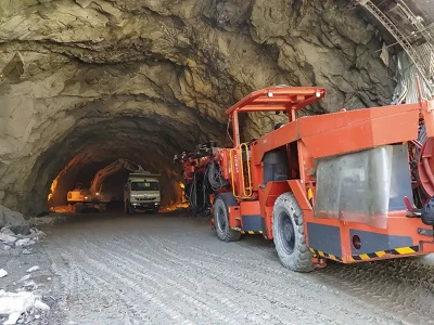
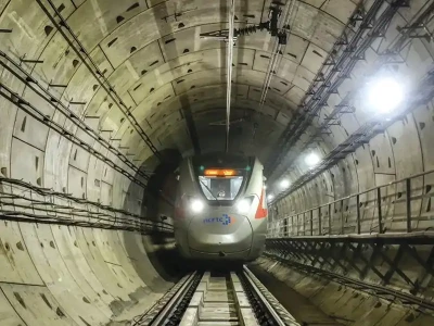
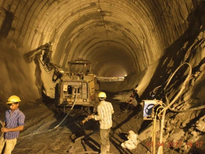
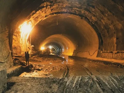
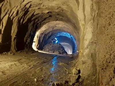
Vishnugad Pipalkoti HE Project is one of the major ongoing projects in the state of Uttarakhand, Chamoli District, designed to generate 444MW of power by harnessing the hydro power potential of the mighty Alaknanda River. Three Desilting Chambers, each with a size of 390 m (L) x 16 m (W) x 21.5m (H) are designed to eliminate suspended sediments from the water conductor system, and minimize the entry of sediments to the powerhouse, and ensure the safety and longevity of the turbines and other underwater parts. Construction of these closely spaced chambers and connecting tunnels posed numerous challenges due to the difficult rock condition, difficult terrain, and complex layout arrangements.
The project shall utilize about 240 m of water head of the Alaknanda River, available in a stretch from Helong in Upstream to Birahi in Downstream. It is a Run- of- the River (ROR) scheme using a diurnal storage. The annual energy generation from the project is estimated to be about 1813 MU.
Main components of the project
- Concrete Gravity Dam of 65 m height with four under-sluices for passing 8004 cumecs of flood discharge.
- Three Power Intakes followed by 03 Desilting chambers each with a size of 390 m (L) x 16 m (W) x 21.5 m (H).
- One Head-Race Tunnel of 8.8 m finished dia and 13.5 km length, to be bored with the TBM and DBM methods.
- An underground Machine Hall sizing 146 m (L) x 20.3 m (W) x 50 m (H).
- An underground Transformer Hall measuring 142 m (L) x 16 m (W) x 24.5 m (H).
- An underground Surge Tank measuring 120 m (L) x 16 m (W) x 35 m (H)
- One Tail Race Tunnel of 8.8 m finished dia and 3.07 km length.
Desilting Chambers
Construction of the Desilting Chamber Complex and its associated tunnels for the Vishnugad Pipalkoti HE Project, was carried out from 2014 to 2023. It involved excavation of three major chambers, each of a size like that of a typical cavern of an underground power station, (Figure 1). The Chamber layouts and associated tunnel works, which were principally sized and dimensioned for silt control purposes, were designed by the approved designer for Tehri Hydro Development Corporation Limited (THDCIL), a PSU of the Government of India. As such the layouts of the tunnels and chambers were optimized principally from a hydraulic viewpoint, with rock- mechanics aspects, considered of secondary importance only. However, in the steep Himalayan topography of the site, steeply dipping geology (phyllites, gneisses and schists) dominated rock conditions, making excavating and reinforcing the Chambers and Intake structures as a challenging task. From the contractor’s perspective the main Chamber constructability issues were wall and crown control, pillar reinforcement and excavation sequencing, whereas for the Chamber Intakes, rockslide stability was of highest concern.Fig.1 shows the Desilting Scheme and location map.
Desilting Arrangements

The desilting of water is proposed to be done in three underground desilting chambers of 390m length and 16m width x 21.5m high. The design discharge through each chamber is 76.29m3/sec + 20% for silt flushing, that is equal to total discharge of 91.53m3/sec. The velocity through the chamber has been kept about 0.35m/sec and smooth flow without turbulence is considered to obtain 90% efficiency for removal of silt particles of size 0.2mm and above.
The shape of the desilting chamber was provided in such a manner that the sediment could easily pass into the flushing ducts at the bottom by sliding over hopper bottom. A sufficient number of holes were provided in the slab at the bottom of the hopper portion to pass the flushing water- deposited silt into the ducts.
For maintenance of the sediment chambers periodically, two platforms were provided on either side, just above the hopper. The platforms are of 1.5m width and duly provided with holes to pass the silt deposited on them. Access to the chamber is provided at the top of the chambers themselves on the sides through adits and shafts. From the top up to the platform ladders have been provided to descend.
Water flowing out of all the three sediment chambers is collected into one tunnel at the end, and it becomes head race tunnel to feed water into the power house. A gate is provided at the end of each sediment chamber, so that individual chambers can be emptied after closing of the gates on either side for maintenance purposes. The gates are operated from a common gate chamber tunnel provided at EL. 1270m. The flushing gates are also operated from the same gate chamber. The intake gates are capable of partial opening so that discharge into the sediment chamber can be controlled and regulated. The silt chamber gates shall remain fully opened or fully closed and used only for maintenance of silt-chambers.
The flushing ducts in each sediment chamber is provided with a gate to regulate the flushing discharge during monsoon and non-monsoon season. During monsoon season continuous discharge is allowed through flushing ducts. During non-monsoon, silt is less in water and hence intermittent flushing is done and thus maximum quantity of water available is utilized for power generation. Therefore, flushing gates shall be capable of partial opening also.
The silt laden water from each flushing duct is collected in one D shaped silt flushing tunnel of size 3.6m x 4m to flush the discharge 45.8m3/sec. The length of silt flushing tunnel is 680m. The design velocity through the silt flushing tunnel is 3.18m/sec.
Geology of the Project Area
The project area forming a part of Alaknanda valley exposes rocks belonging to Garhwal Group and Central Himalayan Crystalline and are composed mainly of calc arenaceous rocks with basic intrusive and migmatite bodies, whereas, around Helong, low to medium grade metamorphic rocks are exposed. The rocks of ‘Carbonate Suite of Chamoli’ of ‘Garhwal Group’ occur between Chinka and Helong and also contain the major magnesite bodies of this region. Generally, the magnesite deposits are restricted to the non- siliceous horizons of dolostones and show a distinct structural control. Pipalkoti Anticline (double plunging anticline) is a regional fold between Birahi and Helong, representing the western continuation of anticlinorium of Tejam.
All the project components are in-between Birahi and Helong. The rocks occurring at the dam and Desilting Chamber site are quartzites and along most of the length of the tunnel alignment are quartzite with biotite schist, interbedded and interbanded with grey slates and dolomites/limestone. Grey thinly bedded slates with minor interbeds of limestone, dolomitic limestone with subordinate grey slates, grey pyritous shale / slates, thinly bedded dolomitic limestones, grey slate / phyllite, white siliceous dolomite with magnesite and talc schist are a common presence. Light grey dolomite with stromatolitic structures, interbedded quartzite phyllite and dolomite, all belong to Garhwal Group. However at the powerhouse site rocks occurring are the calcareous shale and dolomitic limestone / dolomite, while along TRT dolomitic limestone, meta basics, augen gneisses and schist. The rocks overall are very complexly folded and faulted. The rocks of the area can be categorized into four formations viz. Pipalkoti Formation, Chinka Formation, Gulabkoti Formation and Helong Formation.
Intakes and Desilting chambers
Three intake structures in rectangular shape have been proposed on the right bank of the river Alaknanda upstream of the diversion structure. Three intake tunnels designed as 6m modified horse shoe are proposed on the right bank of the river Alaknanda. So far, as the hot water springs are concerned, the same will not create any problem for accommodating Desilting chambers in the right bank as confirmed from the geological investigation. From the available space it is observed that putting the desilting basins downstream of the dam axis on the right bank of the river is the right choice based on the geological investigation carried out. Three numbers of desilting chambers of size 320m (L) x 16m (W) & 21.5m (H) are proposed on the right bank to ran over sediment particles of size 0.2 mm and above.
This hole is located at the 20 m U/S of dam axis in the desilting chamber area. The vertical hole has proved Overburden up to 9 m depth (El, 1318.93 m) below which bed rock consisting of mainly fine grained grayish white- quartzite with a biotite chlorite schist band between 12.45-14.0 m has been met up to drilled depth of 110.3 m (EL. 1208.73 m). The overburden consists of boulders and pebbles of quartzite in a sandy matrix. A thin shear zone has been recorded from 49.50-49.70 m, 57.47-57.65 m, 78.50-78.70 and 91.70-92.40. The percentage core recovery ranges from 80 to 100 percent while the RQD varies from 10 to 100 percent.
Methodology
The excavation and concreting of De-Silting Chambers was done in following steps for all three De-Silting Chambers. The step of Top ramp and Bottom ramp removal and plugging of Adits have to follow completion of activities in DC-3, DC-2 and DC-1 scheduled from Top and Bottom Adit.
After extension of Adits into De-Silting Chamber, junction treatment was done as per good for construction drawings, only then the activities of De-Silting Chamber started.
Excavation of Adit to Desilting Chamber Top & Bottom
Excavation was done by drill-blast method, using Two Boom Hydraulic Drill Jumbo for drilling, excavator PC-200 or equivalent and 10T/ 18T dumper for mucking, Two Boom Hydraulic Drill Jumbo for rock bolting and Shotcreting equipment with robo arm (Cifa/ Normat or equivalent) for shotcreting. Generated muck was disposed to the nearest dumping yard from Adit to DC top.

Excavation of Pilot Tunnel and side slashing inside Desilting Chamber
Excavation of pilot tunnel 8m x 8m, D-shape was carried out in both Up-Stream and Down-Stream directions after extension of Top adit into DC by drill & blast method. Drilling and charging activity was carried out with the help of 2 Boom Hydraulic Drill Jumbos.
Scaling was done after blasting and de-fuming to avoid any incident by removing any visible fallout rock mass. Scaling was done with excavator PC-200 or equivalent or manually with the help of crowbar.
As soon as scaling is completed, geological mapping of the face and crown was done and 3-D log to be maintained from time to time.
Initial layer of sealing SFRS to be applied if required to support the rock mass after blasting. Shotcreting was done with the help of shotcrete machine with robotic arm and 4Cum/6Cum Transit mixers available at site.
Mucking activity was carried out with the help of Side dump loader CLG 856 or equivalent and 10T/18T dumpers. Generated muck was disposed to the nearest dumping yard from Adit to DC top.
Permanent cement grouted rock bolts of 25 dia and 6m/ 8m with c/c spacing as per rock class was done after mucking is completed.
Permanent SFRS shotcreting as per rock class was carried out after rock bolting activity. Shotcreting was done with the help of shotcrete machine with robo arm.
After excavation of 390m long pilot tunnel, slashing works to be carried out in the same sequence as explained above for pilot tunnel.

Drilling & blasting of 1st bench of 2.5m
Activity comprises of only drilling & blasting of 1st bench to provide platform for concreting works of 1st beam and wall portion. Drilling was carried out with the help of ROC-203. Ramp was prepared in a gradient of 1:10.
Drilling & blasting then carried out in both directions from Adit to DC Top. Drilling was done with the help of ROC-203, after leaving 6m from either sides of Adit to DC top for turning and smooth movement of traffic.

Muck removal after Drilling & Blasting of 1st Bench
Mucking activity was carried out with the help of Side dump loader CLG 856 or equivalent and 10T/ 18T dumpers. Generated muck was disposed to the nearest dumping yard from Adit to DC top.
Permanent cement grouted rock bolts of 32dia and 6m/ 8m with c/c spacing as per rock class was done after mucking is completed.
Permanent SFRS shotcreting as per rock class then carried out after rock bolting activity. Shotcreting was done with the help of shotcrete machine with robo arm.
Muck removal was done from Adit to De-Silting Chamber Top.

Drilling & blasting of 2nd bench of 2.5m
Activity comprises of only drilling & blasting of 2nd bench to provide platform for concreting works of 1st beam and wall portion. Drilling was done with the help of ROC-203. Ramp was prepared in a gradient of 1:10.
Sand bags were used to cover the blasting area to avoid damage in wall concrete due to fly rocks.
Muck removal and permanent rock supports was done as explained in Section 7.2.5 after concreting of 2nd lift of side walls.
Muck removal was done from Adit to De-Silting Chamber Top.

Drilling & blasting of 3rd and 4th bench up to hopper top
Activity comprises of only drilling & blasting of 3rd bench to provide platform for concreting works of wall portion. Drilling was done with the help of ROC-203. Ramp to be prepared in a gradient of 1:10.
Muck removal and permanent rock supports was done as explained in Section 4.5 after concreting of 3rd lift of 2.5m explained in Section 4.9.
Muck removal was done from Adit to De-Silting Chamber Top.

Concreting of Desilting Chamber up to the 4th bench of 10m
Reinforcement fixing for the beam and wall portion up to a height of 10 m was accomplished in a single operation using 5m shutters. The reinforcement fixing for the 10 m height was carried out manually using staging and scaffolding. To prevent sagging of the reinforcement, anchor bolts were inserted according to the design specifications before concreting.
The concreting of the beam and wall was executed with the assistance of standard shuttering plates with a height of 5 m. The concrete was compacted using mechanical vibrators. The grade of concrete used was as per the design, with a specification of M25, and the maximum size of the aggregate used was 40mm. Contact grout holes, as specified in the design, were provided by inserting PVC pipes during concreting.
Concreting was done by a concrete pump and 6Cum Transit mixers. The concrete was supplied through Adit to DC Top from the nearest batching plant located at the dam site. Sandbags were placed under the wall portion to prevent slurry leakage, and reinforcement bars were curtailed inside for further tying down.
Proper treatment was applied at construction joints before resuming the work. The junction between the crown shotcrete and wall concrete was filled with SFRS to rest on the concrete wall.

Excavation of 5th bench of 2.75m
Sequence of execution is same as explained earlier was followed. Muck removal was done from Adit to De-Silting Chamber Bottom.

Excavation of Construction Adit to Flushing Trench up to DC, Excavation of 2nd Ramp and Trench
Construction adit (Adit to Flushing Trench) interconnecting all three DC’s was done to facilitate for excavation and concreting works of part wall and trench portion which shall be plugged after completion of DC works instead of enlarging all BFT’s for excavation and concreting purpose which resulted excess cost. Sequencing of works is explained below considering this construction adit in place.
Excavation of Adit to Flushing Trench up to DC was completed to provide passage for further activities inside DC.
Excavation of Adit was done from Silt Flushing Tunnel (SFT) towards DC. Adit was excavated in a minimum dimension of 4m D-shaped for effective and smooth working and was plugged with concrete after completion of works in DC.
The junctions with trenches were flared for getting required turning radius for equipments to move inside DC; same was backfilled with concrete and will become a part of plug structure.
Excavation sequence is the same as for any tunnel by Drill Blast Method (DBM)
a) Drilling b) Charging & Blasting c) De-fuming d) Scaling & Mapping e) Initial sealing Shotcrete or SFRS (if required) f) Final Rock support
Excavation of 2nd Ramp was carried out by drill & blast method. Drilling was done with the help of ROC-203.
Completion of Excavation of Adit to Flushing Trench from SFT was ensured before excavation of ramp and below ramp portion for mucking purpose.
Drilling & blasting of Trench area then carried out. Drilling was done with ROC-203. Ramp was prepared in a gradient of 1:10.
Muck removal and permanent rock supports were done as per the requirement.

Concreting of hopper portion and trench
Concreting of hopper portion was done only after excavation of DC up to trench level. Concreting method is same as done for walls except for the shutter used with gantry traveller. Concrete was supplied from Adit to Flushing Trench. Shutter length considered is 6m.
Concreting of trench was done after concreting of hopper portion and gantry removal with the help of traditional shuttering.
Concrete then supplied through Adit to Flushing Trench from nearest Batching plant located at dam site.

Equipment Used
Most modern equipments were used for excavation and concreting of various stages oDC-1.2 &3 as explained below:
Pilot Excavation and Arch Slashing:
Two Boom Hydraulic Drill Jumbo: 1no
Side Dump Loader CLG 856 or equivalent: 1no
Excavator PC-200 or equivalent: 1no
Shotcrete machine 30m3/hr: 1no
Dumpers 18T: 5nos
Transit Mixers 4Cum: 6nos
Benching
ROC 203 or equivalent: 2
Excavator PC-300/200 :2nos
Shotcrete machine 30m3/hr: 1no
Dumpers 18T: 5nos
Transit Mixers 4Cum: 6nos
Concreting:
Transit Mixers 6Cum: 6nos
Batching Plant 60m3/hr: 1no
Safety Precautions: Risk Hazard Assessment
All safety measures to be followed as per the standard Safety Management Plan.
Operator & supporting labour staff shall put on necessary PPEs during the work at heights as proposed.
During excavation, the excavated profile shall be cut in specified shape and dimensions with designed rock support methods to ensure safe working area.
Scaffolds of proper type shall be provided for all work that cannot be done from the ground or from part of a permanent structure or from ladder or other available means of support and safe means of access shall be provided to every place at which workers are required to work.
All working platforms, gangways and runs from which workers are liable to fall more than 2 meters shall be:
a) Of adequate width depending upon the type of work done and closely boarded, planked or plated. For platforms, the width shall not be less than 60cms. For gangways or runs are used for passage or materials the width shall not be less than 60 cms.
b) Provided with suitable guardrails of adequate strength to height of 1 meter above the working surface and toe-boards of at least 20cms in height to prevent fall of persons, materials or tools.
In addition to the above listed precautionary and safety measures. certain IS codes for safety norms enlisted in the table should also be strictly followed:

Difficulties in Construction
During execution, a lot of problems are faced by the working team. Some of the major problems are highlighted below:
Managerial Difficulties in Streamlining the VPHEP
While talking about poor geology as a major challenge to the underground work, we often tend to overlook many other extraneous factors which cause serious delay in execution of the project. Coupled with it stand out the hostile local populace and remote location of site.
The VPHEP was planned to commission by 2025 but has been inordinately delayed. Local people have posed lot of problems to the project authorities and contractors: viz, non-transfer of land required for the project even after drawing 75% of the payment as compensation, and raising issues related to employment and petty construction-contracts. Authorities have assured employment to local people and given them a chance to work in the project on the basis of their qualifications. After getting the job they more than often formed a union in connivance with local leaders and collected hostile-rabble-rousers and disrupted the smooth functioning of the company authorities and district administration. Instead of silently working on the posts allotted to the local workers, they engage in protest marches and sometimes in pilfering construction material too. The company has lodged several FIRs in this matter and has also removed some hostile staff from the project. Project activities are seriously hampered due to local disturbances and continuous strikes, for more than a month at a stretch. As a result, in 7 year only 14% work of the project was completed.
Finally, the work started at this site but still the project is moving ahead with the re scheduled dates. It looks from the speed picked up now work will be completed soon with support of authorities.
Dam site at Helong stands at a remote location near Joshimath where the Project components like diversion tunnel, desilting chambers, silt flushing tunnels, part HRT and intake structures which are the starting points of the project, could not be made functional because authorities faced a lot of problem due to non- cooperative attitude of local people. Alternative ways were explored by the management and, in some cases, paid an extra amount to carry on the works. Several cases of manhandling occured involving engineers and staff working at site. Such cases were given legal cognizance reported thereof.
Finally we restored the work sequence by doing efforts and educating people with help of district administration.
The blockade of National Highway especially during the monsoon, made the situation worse: supply chain management was severely affected. As a result, construction material like cement, steel, structural steel could not reach the site on time. Storage facilities were limited for want of flat land available in the region. Lack of diesel storage also created hurdles and further delayed the execution of the project. Internal road links passing through the acquired land of the locals were also laid seizure upon by the so-called owners who continue demanding undue compensation. It also delayed the project schedule.
Construction of Char Dham project, a govt project, was started to widen the roads and to give good accessibility to pilgrims. The project also created interruptions during its implementation which was further complicated by the huge rush of vehicles during the yatra season.
Covid -19 also gave a big setback to the project. All movements were stopped by govt Nakas at different places even for human movement documents were demanded, at every nakka, for vehicles carrying construction materials. This severely delayed the project.
Transportation of big equipment was hit the most. Equipments were transferred in various consignments to the site after strengthening the weak bridges and dismantling big equipment’s in pieces and then reassembling at the site. This was a major exercise which directly caused enormous delay in mobilization of equipment’s to the site. Lot of innovative thinking was given to identify safe routes for the equipment’s to reach the site. Finally, with the help and cooperation of local authorities we could mobilize the site but huge wastage of time did take place.
Problem in vertical wall concreting in desilting chamber and innovative solution adopted
Vertical wall concreting was critical activity and very time consuming, to overcome this 10m shutter was introduced and 5m length of vertical wall was done at a time on each wall by providing 2 shutters in each chamber. This proved to be a successful innovation and concreting was done in a faster way.
Non availability of Dumping Yard
Dumping space at dam site was limited and after continuous dumping the space got occupied fully. By providing gabion walls to some extent the space was increased but that also was not sufficient. Then with the consent of THDCIL some local land was taken on lease for dumping at a distance within 7-8km and this arrangement worked well and work was done in a faster way.
Conclusions
The scheme, the considerably big in India at 444 MW, will generate power after completion with the Desilting Complex Chamber excavations and ancillary tunnels providing their designed role.
Despite so many problems requiring significant engineering input, the Desilting Complex, comprising three Chambers 390m long, 16m wide, approximately 21.5m high has been completed to the original hydraulically designed shapes. Execution of the final works has not been without challenges however, and the final arrangements have only been accomplished through the cooperation and integration of important ideas put forward by many parties, and then engineered to detailed design level only as part of the construction works. The overall final arrangements now comprise several support elements not foreseen in the original tender design drawings and by introducing in-house innovation at project level, this was the key of success to complete these important structures.
Acknowledgment
The author is thankful to THDCIL for giving this opportunity to execute the job and all the support extended during execution of this prestigious project.

For more details, please contact:
References
- DPR of Vishnugad Pipakoti Hydro Electric Project’
- Rock mass classification and support design- NGI, OSLO, June 2022
- Tunnelling in week rock Elsevier Geo engineering book series vol.5, Elsevier, Amsterdam (2006)
- Underground excavation in rock, E.Hoek & E.T. Brown
- Geotechnical Engineering Office, Civil Engineering Department, The Hong Kong,- Geoguide 4, Guide to Cavern Engineering
- Xiao Liu, Peng Yan, Ming Chen, Sheng Luo- Wuhan University, China- Optimization analysis of excavation procedure design of underground powerhouse under high in-situ stress in China.
- Design and construction aspects of desilting chamber of Teesta-III, B.K.Ojha, Project director, Navayuga Engineering co Pvt. Ltd.