TBM Launching Near Seashore: Ground Improvement by ITD Cementation
Dr. Tanumaya Mitra, Sudip Kumar Koley, Padma Tiruvengala, Naru Raju, and Prodyot Kumar Ray, at ITD Cementation India present the ground Improvement requirement for a TBM launching under Shallow Overburden close to a seashore.
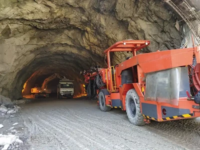
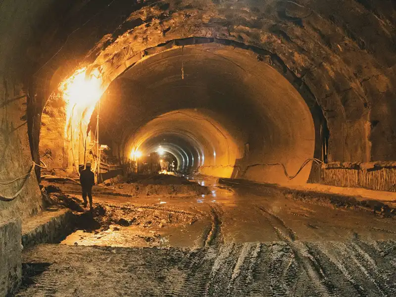
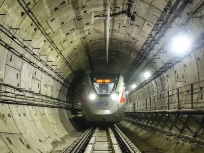
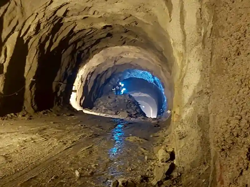
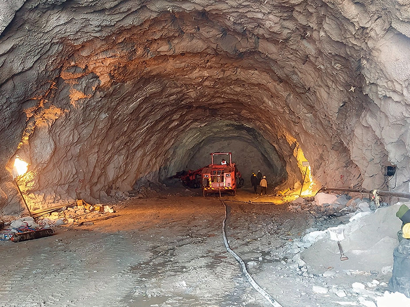
Tunneling under shallow overburden is always a challenging aspect due to the possibility of blow out because of application of higher face pressure or segment uplift as there are always certain lengths of tunnel linings located in the unsolidified grout. As a result, the buoyancy induced by unsolidified grout and hydrostatic pressure may be higher than the lining gravity, which leads to the lining uplift tendency.

The presence of a high water table complicates the situation even more. In the current project, TBM launching site was very close to the seashore line. The water table is almost at ground surface. Soil cover above the TBM tunnel varies from 4m to 6m for about 70 m length from the launching shaft. The soil profile consists of 6.0 m thick loose to medium dense silty sand (Navg = 8) followed by 5.5 m thick loose silty sand (Navg = 3-4) layer underlain by 4.5 m thick, soft to very stiff sandy clay layer (Navg = 22) and silty sand layer, respectively.
The combination of low soil cover, presence of a high water table and loose silty sand makes the TBM launch a daunting task. Prediction of ground movements is an essential task prior to TBM tunnelling. Hence, assessment of predicted ground movements using 2D and 3D numerical analysis, simulating the field conditions, was done.
3D Numerical Modelling of Tunneling Using EPB TBM: The steps include application of face pressure, excavation of soil slices, tail void grouting, advancement of TBM with thrust force from hydraulic jacks and installation of tunnel lining segments. A slurry wall was considered in front of the TBM launching area.
2D Numerical Modelling of Tunneling Using EPB TBM: A 2D analysis was also carried out using the same parameters to simulate the field condition. Maximum ground settlement obtained from the 2D analysis is presented in Fig. 3 and Table 2.

Proposal of Ground Improvement Scheme and Requirement of Ground Improvement for Initial Drive
M10 concrete PCC panels of 10.0 m Length and 2m below the tunnel invert level
- For preventing inflow of groundwater in the launching shaft
- For limiting the potential settlements, to avoid excessive loads on D/Wall
Permeation grouting / TAM grouting
- For preventing the running ground / cohesionless soil with water into cutter head during the initial drive after passing through the PCC panels.
- For reducing the permeability of the sandy soil.
- For minimizing ground movements during the initial drive under shallow overburden.
Application of Surcharge in the form of sand filled muck box
- For preventing blow out due to accidental high face pressure
- For preventing segment uplift

Figure 4 shows the Plan of the TAM grouting area divided into six areas. The outer periphery is for Curtain grouting. The plan of the TBM launching and initial drive zone along with the provisions of PCC panels and muck carts is depicted in Fig. 5.

Groutability check was done using the criteria proposed by Huang et al. (2007). Initial Trial field works were carried out. Based on the observations of the Trial works, modification in terms of grout quantity and the methods was decided. Curtain grouting was carried out using the combination of Sodium silicate and OPC grout at 1.0 m c/c all around the periphery of the area considered for the grouting. Primary grouting carried out using 1:1 mix using OPC and water and later secondary grouting and tertiary grouting carried out based on the requirement.
6 Number Field Permeability Tests carried out pre & post TAM grouting. 3 number test results at 5m to 6m test depth had to be discarded for comparison as Ground Water Table was affecting the test results.

Instrumentation and Monitoring were done by placing ground settlement markers along different arrays to monitor the ground deformation due to tunneling . The maximum settlement at the chainages mentioned in Table 4 is 54.0 mm and 60.0 mm under an overburden of 4.5 m to 5.1 m. Table 5 presents the comparison of ground settlement values obtained using numerical analysis and I & M data.