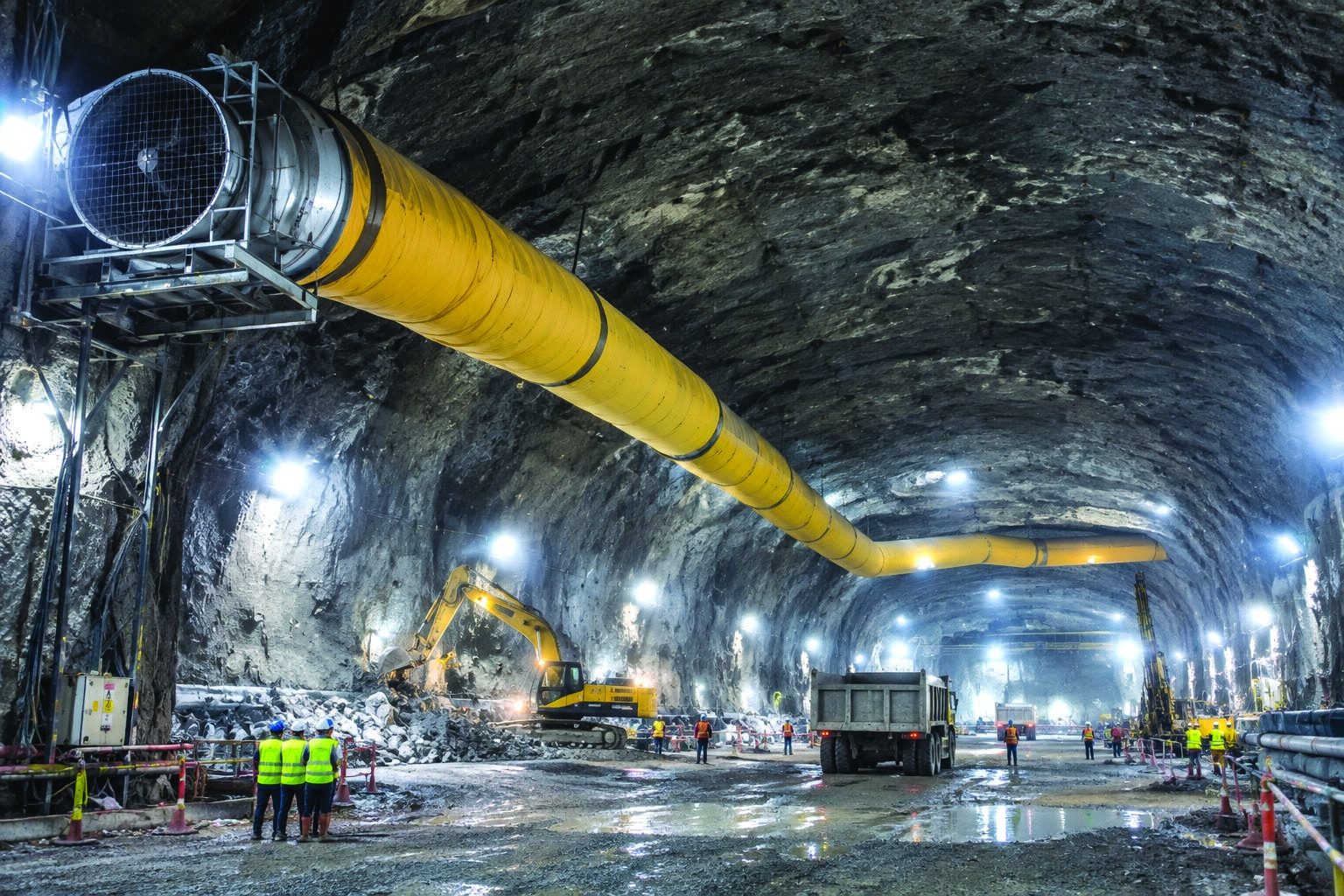
As underground caverns grow in scale and excavation advances deeper, maintaining safe working conditions becomes an increasingly complex engineering task. This technical paper by Dr. R. K. Khali, Senior Vice President, and Naveen K. Bahuguna, Senior General Manager, GR Infraprojects Limited, examines the staged planning of a ventilation system for the Dibang Hydropower Project. Using computational fluid dynamics (CFD) simulations, the study evaluates airflow, duct configurations, pressure losses and fan power requirements to develop a ventilation strategy suited to the changing demands of cavern excavation.
Abstract
Ventilation is needed for underground caverns to provide breathing air to the personnel working inside, provide fresh air quality by removing atmospheric contaminants such as gases and dust, and provide oxygen and cooling for operating vehicles/construction equipment in the cavern.Environmental conditions such as temperature, gases, and airflow concentration have to be controlled and kept within an acceptable range in underground structures where there is a fleet of construction equipment and working crews. The ventilation system therefore has to take into account all the ventilation parameters to deal with efficiency and health and safety issues at the same time.
The design of ventilation system for construction of large underground caverns is very crucial to deal with efficiency, health and safety issues. As underground cavern sizes increase, the airflow quantity that reaches the deepest part usually decreases due to an increase in airway resistance which then reduces the fan performance and air quality in this area. This issue requires a detailed CFD analysis.
The aim of this paper is to design an effective system for managing an underground environment for safe working during construction with the help of CFD simulation studies, and propose an optimum ventilation system for large underground caverns with respect to air quality and power consumption.
Introduction
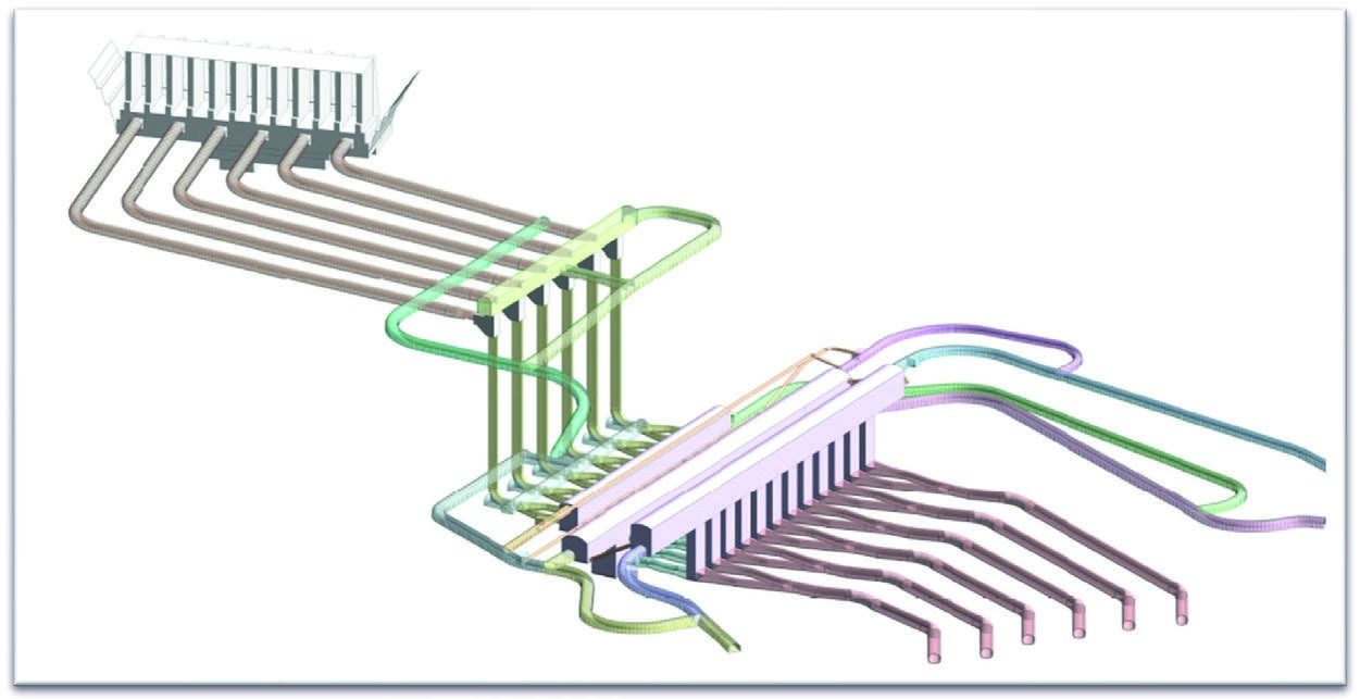 Figure 1: Layout of Water Conductor System
The underground power complex comprises three large caverns: the Main Inlet Valve (MIV) cavern (17 m W × 29.1 m H × 250 m L), the Powerhouse cavern (23.5 m W × 54.3 m H × 427 m L), and the Transformer cum GIS cum Draft Tube Gate cavern (19 m W × 31.5 m H × 407.8 m L). Multiple adits and access tunnels have been planned to facilitate construction, including two D-shaped tunnels of 6.5 m diameter leading to the MIV cavern at EL 286.0 m and EL 264.8 m, respectively. For the powerhouse cavern, two 6.5 m D-shaped adits are provided, one at EL 262.4 m from the MIV floor and another at EL 301.3 m connected to the cable-cum-ventilation tunnel (8.0 m D-shaped). Two 9.0 m D-shaped main access tunnels (MAT-1 and MAT-2) will approach the powerhouse service bays at EL 283.7 m. Similarly, construction of the transformer cavern will be supported by a 9.0 m D-shaped access tunnel at EL 312.5 m and an 8.0 m cable-cum-ventilation tunnel at EL 334.5 m.
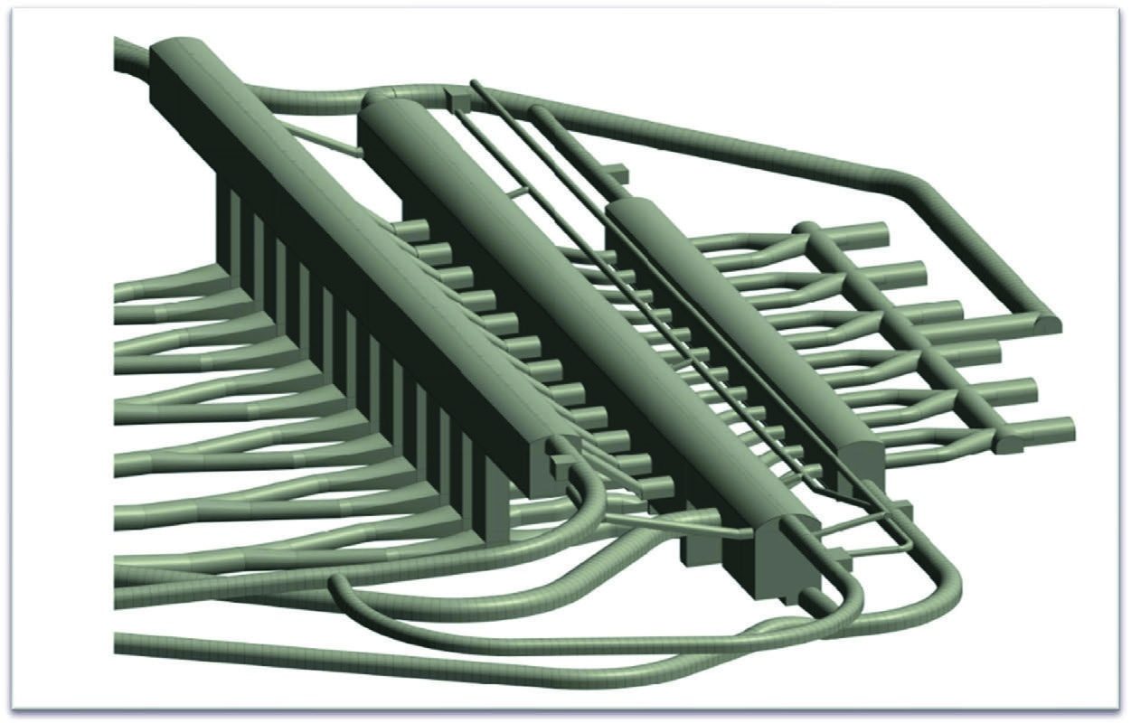 Figure 2: Underground Caverns Layout
Materials And Methods
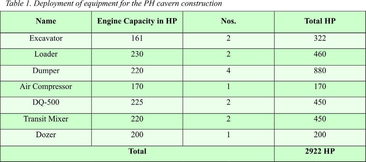
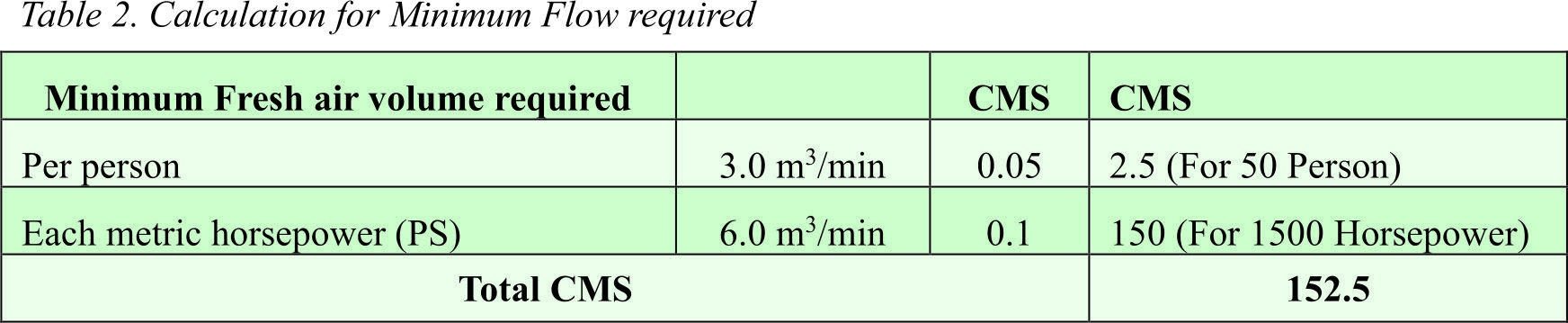
The maximum utilization of above deployed HP considering load factor as 50% and hence total horsepower requirement will come down to 1461 HP. Accordingly, temporary ventilation system is computed for 1500 HP requirement.
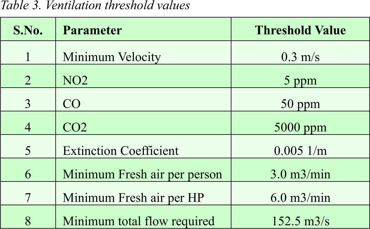
The following table indicates the minimum threshold value to be maintained inside the caverns
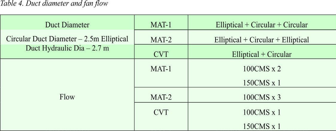
Following duct diameter and fan flow have been considered for simulation purpose:
Pressure drops and Friction factors are computed using CFD analysis:
Flexible ducts, typically constructed from a combination of rigid circular reinforcement and flexible sheet lining, exhibit complex flow behavior at high velocities. Under such conditions, turbulence significantly alters the effective friction factor, necessitating detailed analysis rather than reliance on empirical values alone. To quantify this, Computational Fluid Dynamics (CFD) simulations were carried out for both circular and elliptical ducts.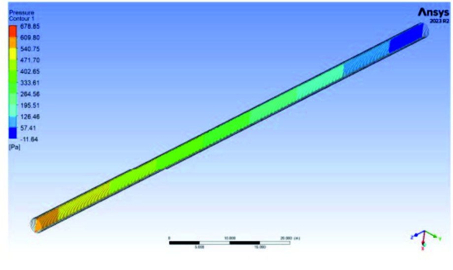 Figure 3: Circular Duct
The key parameters for the 3D CFD simulations are summarized as follows:
● Mesh size: 0.05 m, fully unstructured polyhedral mesh
● Inlet velocity: 16.7 m/s and 25 m/s (depending on duct configuration)
● Air density: 1.15 kg/m³
● Turbulence model: k–ω SST
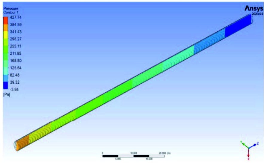 Figure 4: Elliptical Duct
The stages of excavation and their corresponding ventilation schemes are explained below:
Stage 1: Extension of Adit to powerhouse top and Adit to powerhouse bottom through the full length of powerhouse.
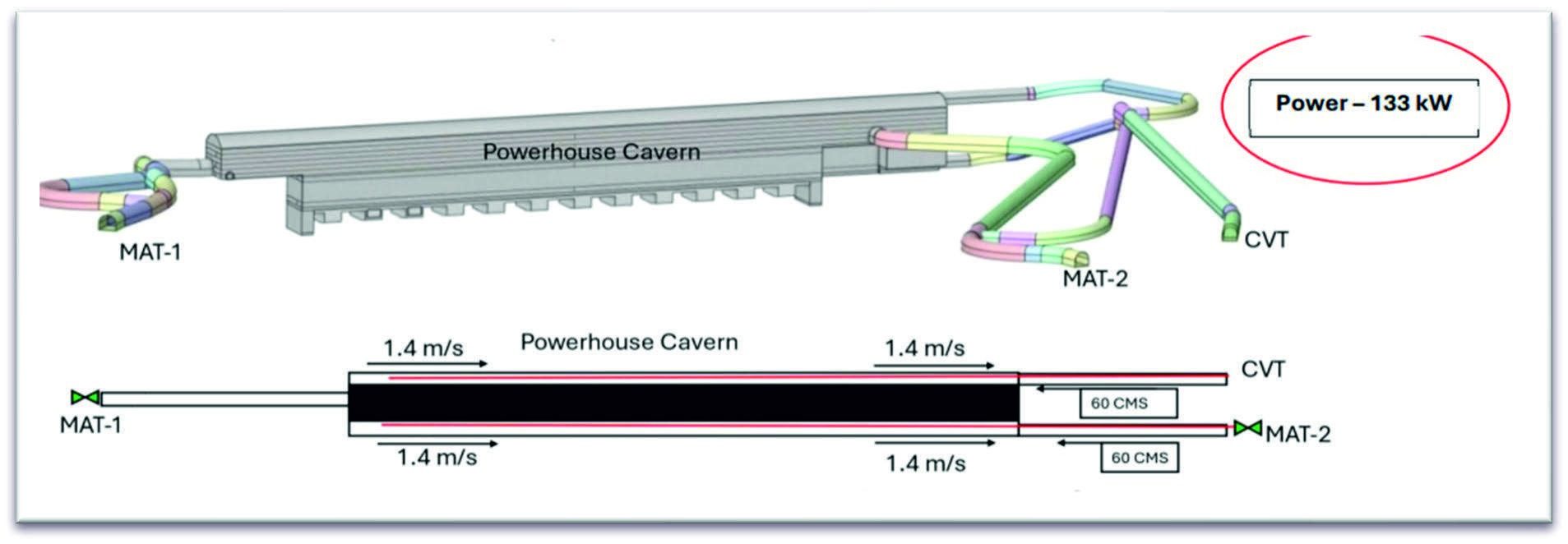 Figure 5: Stage 1 ventilation scheme
Stage 2: Sidewise Excavation of Adit to Powerhouse Top for full width of Powerhouse.
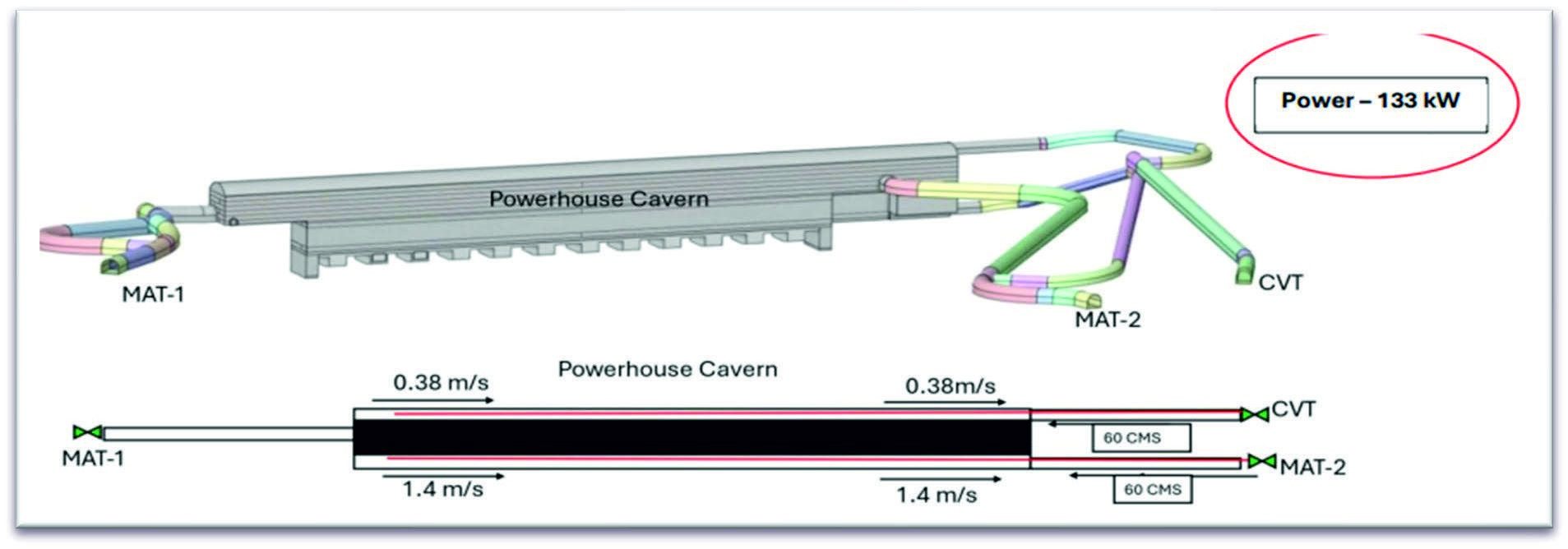 Figure 6: Stage 2 ventilation scheme
Stage 3: Total 6 no. of pilot shafts of diameter 2.1 m will be completed.
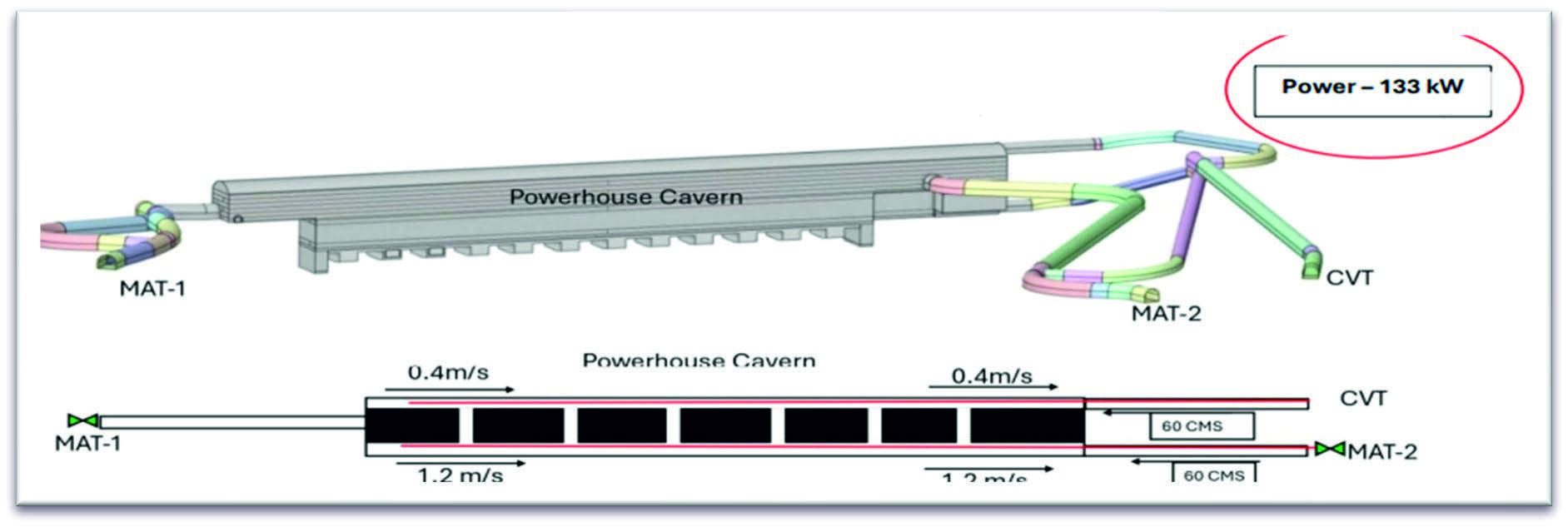 Figure 7: Stage 3 ventilation scheme
Stage 4.1: Partial bench down excavation above service bay level
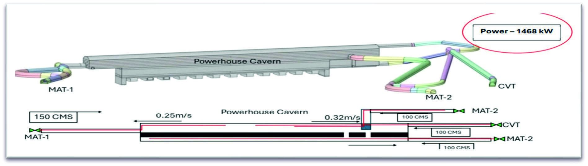 Figure 8: Stage 4.1 ventilation scheme
Stage 4.2: Partial bench down excavation up to service bay level
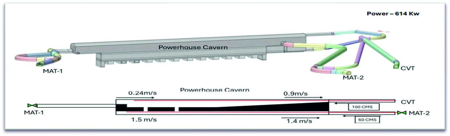 Figure 9: Stage 4.2 ventilation scheme
Stage 5: Full bench down excavation up to service bay level
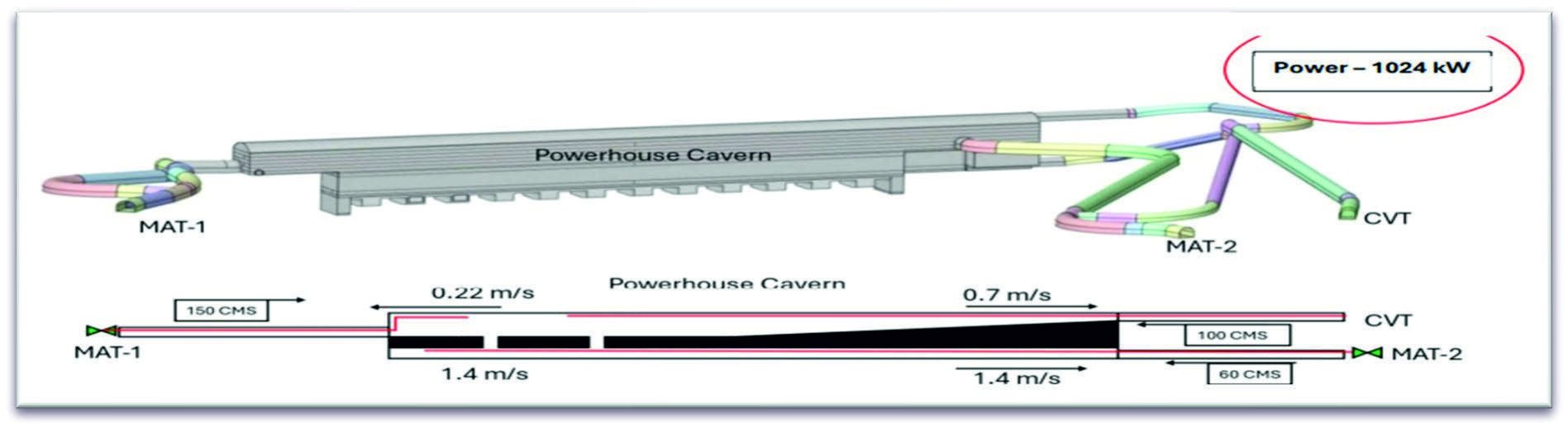 Figure 10: Stage 5 ventilation scheme
Stage 6: Partial bench down excavation below service bay level
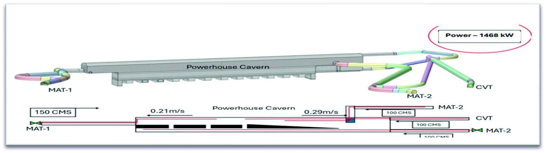 Figure 11: Stage 6 ventilation scheme
Stage 7: Full bench down excavation of powerhouse cavern.
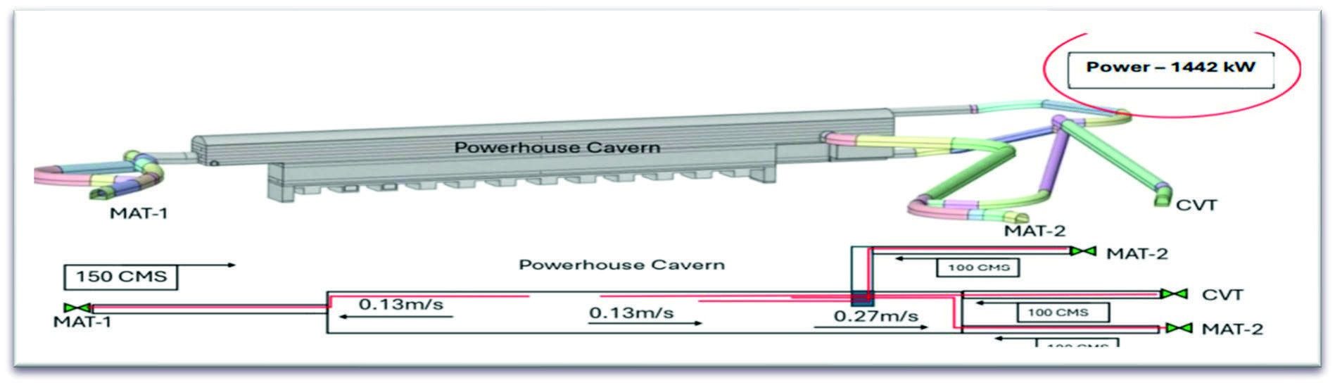 Figure 12: Stage 7 ventilation scheme
For the simulation of CO, NOx & opacity emissions, each simulation was runs for 20 minutes, and the peak values of the noxious gases were monitored and displayed in graphs.
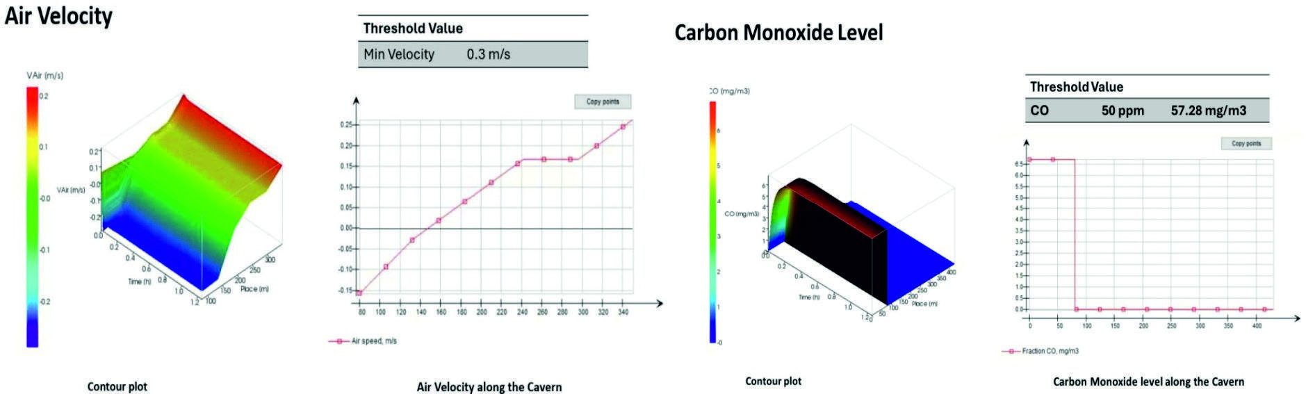 Figure 13: Air Speed / Figure 14: CO level
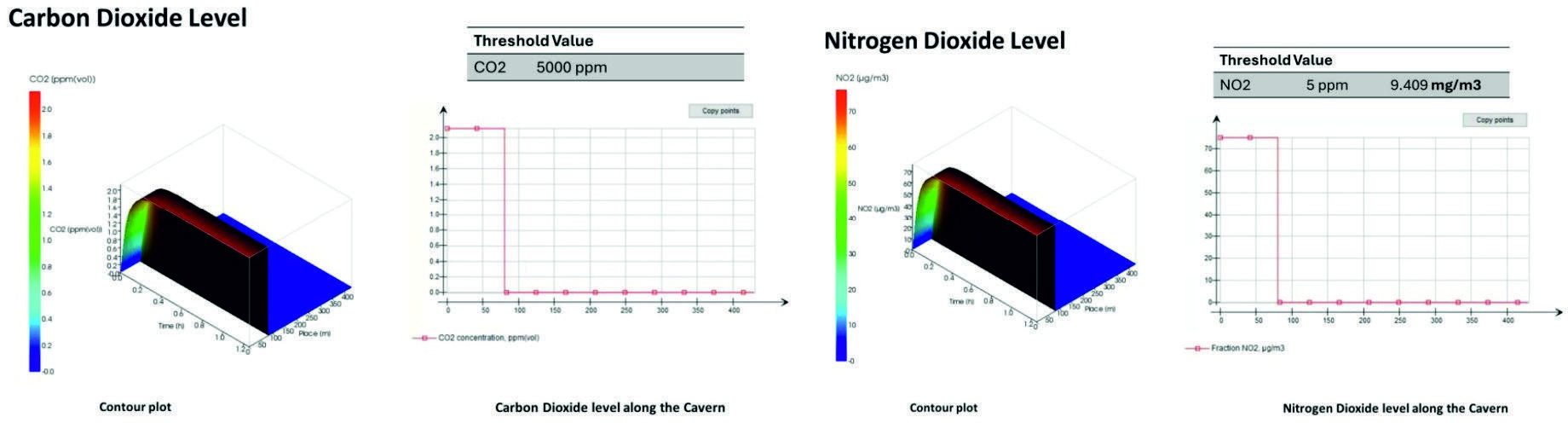 Figure 15: CO2 level / Figure 16: NO2 level
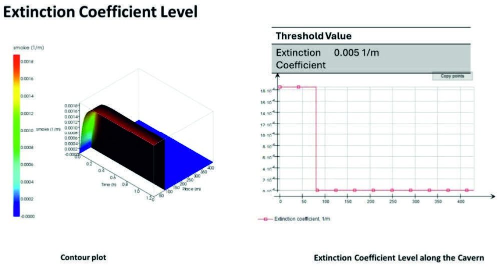 Figure 17: Extinction Coefficient
Results and Discussion
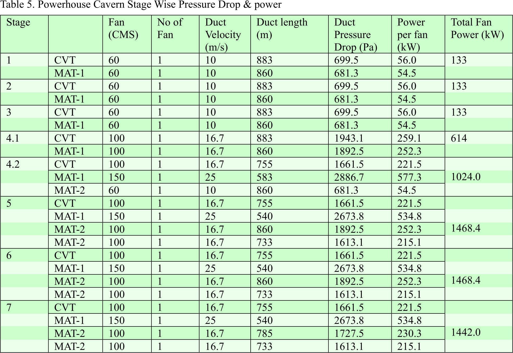
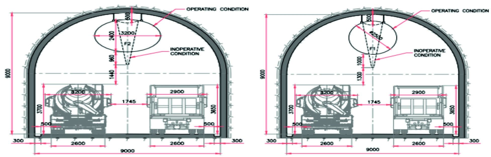 Figure 18: Access tunnel to Service bay-1 via MAT-1 / Figure 19: Access tunnel to Service bay-2 via MAT-2
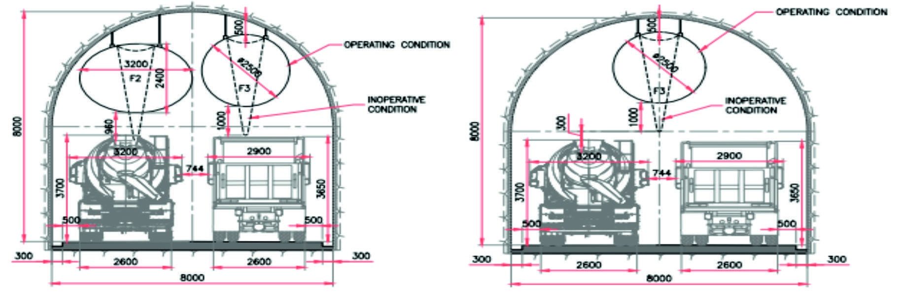 Figure 20: Adit to PH Bottom via MAT-2 / Figure 21. Adit to PH Top via CVT

Conclusions
The design of duct systems for large underground caverns is constrained by the limited clearance available in the Main Access Tunnels (MATs) and the Cable-cum-Ventilation Tunnel (CVT). In addition, minimum airflow velocities must be maintained within the excavated sections to ensure adequate dilution of contaminants. Smaller duct diameters, while easier to handle, lead to higher air velocities and consequently excessive pressure drops. These conditions may induce duct instability, vibrations, and noise, posing safety risks to the workforce. Moreover, prolonged fan operation under stall conditions significantly increases the likelihood of equipment failure. For this reason, duct velocities should not exceed 25 m/s. To mitigate these risks, the use of ducts with at least 2.5 m circular diameter or 2.7 m hydraulic diameter (elliptical) is recommended.CFD-based simulations were performed for multiple excavation stages of the powerhouse cavern. The main outcomes are summarized below:
- A minimum of 153 m³/s of fresh air was ensured across all excavation stages, meeting the requirements of both the workforce and equipment, except in Stages 1 and 2 where the demand was proportionally reduced.
- The target threshold velocity of 0.3 m/s was consistently achieved through combinations of 50 and 75 m³/s fans.
- The minimum number of fans required for the powerhouse cavern is eight (six rated at 50 CMS and two rated at 75 CMS).
- Concentrations of CO, NO 2, and particulates were maintained below the permissible threshold limits.
- Given the progressive nature of excavation, Variable Frequency Drives (VFDs) are recommended for adjusting airflow in real time.
- Following each blast cycle, fans should operate in extraction mode for at least 30 minutes to evacuate residual fumes.
- Pressure losses increase significantly with smaller duct diameters; therefore, larger ducts are essential for operational stability.
- The effective duct length for each stage should be limited to 15–20 m, with extensions added progressively as excavation advances.
References
- GRIL, Amberg Engineering (2024). Simulation report of MIV, PH, TR & Associated Build Environment for Dibang Hydro Power Project).
- Sharma, Ashok Kumar, (2020). Tunnel Ventilation System- During construction. IARJSET ASCE Journal, Vol-7, Issue 4, April 2020.
- Fang Lin (2018). Construction Network Ventilation System for an Underground LPG Storage Cavern. Civil Engineering journal Vol-4, No. 7, July 2018.
- Adrian Halin, Catrin Edelbro (2020). State-of-the Art Underground Ventilation. Rock Tech Centre, Lulea University of Technology.