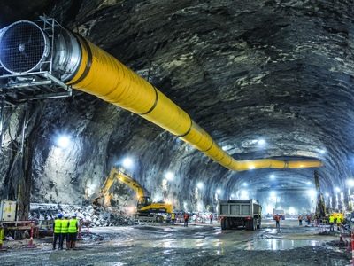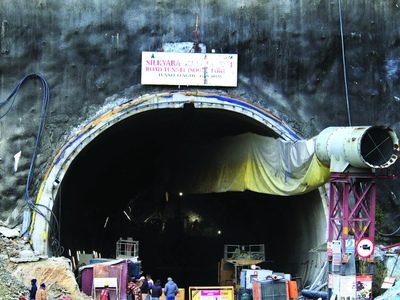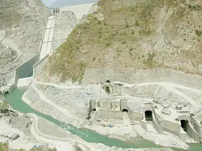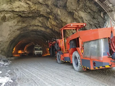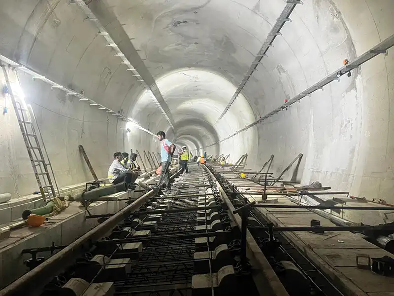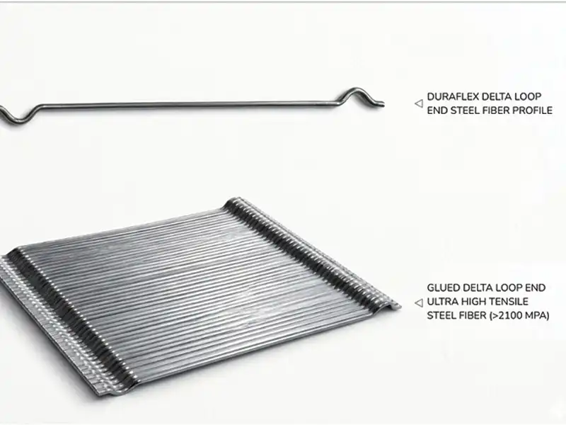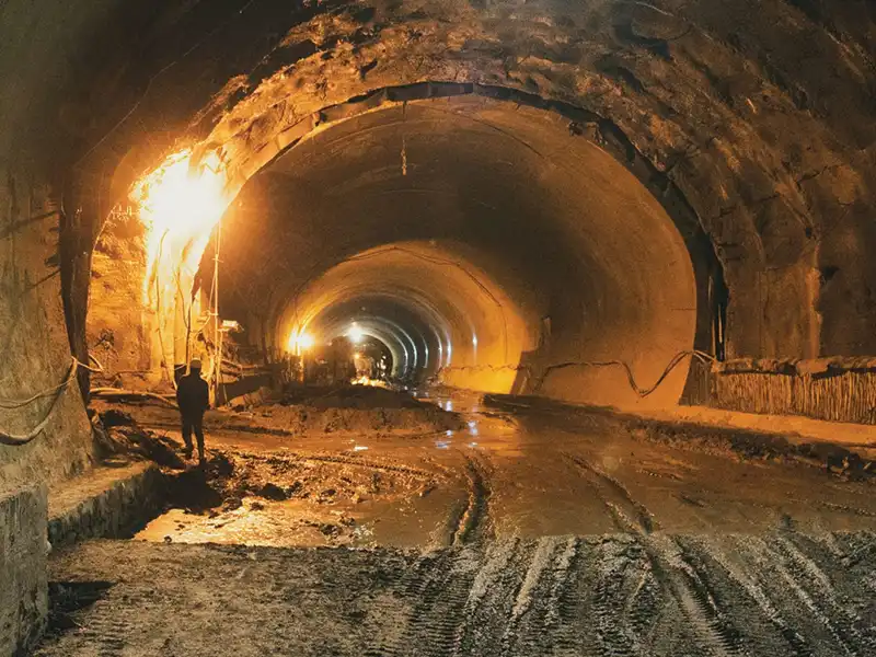
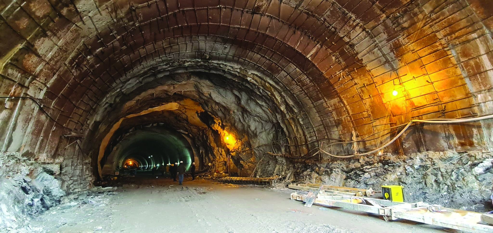
From the Seri Nala shear zone and rock-bursting at the Atal Tunnel to the extreme conditions encountered at Sela and Nechiphu, Himalayan tunnelling has demanded innovative responses to complex site conditions. L.M. Singh, Border Roads Organisation, and R.K. Dhiman, Tunnelling Association of India, illustrate how field conditions, evolving ground behaviour and logistical constraints shaped construction strategies, offering valuable lessons for the planning and successful delivery of future tunnel projects in challenging terrains.
Abstract
A unique combination of geological, logistical, and environmental challenges makes tunnel construction in the Himalayas an extremely tough undertaking. The Himalayas are characterized by young, tectonically active, and highly fractured rock masses, often exhibiting unpredictable joint patterns, shear zones, and thrust faults. The presence of varied lithologies, ranging from weak shales and phyllites to hard quartzites and granites, further complicates excavation and support design.High in-situ stresses, coupled with deep overburden, frequently lead to phenomena like rock bursts, squeezing ground, and face instability, demanding advanced pre-support and ground improvement techniques. Hydrogeological challenges are pervasive, with high groundwater ingress and glacial melt water posing risks of flooding, slope instability, and difficult working conditions. Cold weather conditions, freezing temperatures, snowfall, and avalanches severely impact construction schedules, equipment performance, and worker safety.
Introduction
The challenges faced during tunnelling in this region stem primarily from its status as a young, seismically active, and tectonically compressed fold belt. Extreme geological conditions are often vastly different from pre-construction predictions, leading to significant project delays, massive cost overruns, and safety concerns. Due to the active collision and massive overburden (up to 2 km or more), the rock is under immense stress. This leads to severe squeezing and rock bursting. The fractured rock mass acts as a conduit for extensive groundwater flow.The Atal Tunnel encountered the highly problematic Seri Nala fault zone, a 587m stretch of water-saturated, highly fractured rock, which acted as a geological "surprise." This led to severe face collapses, huge water inrushes (~8000 liter per minute), and major construction delays for nearly three years (Verma et al. (2021)).
The tunnel passes under an overburden of up to 1.9 km, which resulted in severe squeezing ground conditions and time-dependent rock deformation, requiring constant monitoring and adjustment of support systems (Dixit et al., (2025)). The project successfully employed the adaptive NATM in conjunction with the DRESS (Drainage, Reinforcement, Excavation, and Support System) principle. This involved extensive pre-drainage, pipe-roof support systems (pipe umbrellas), and highly flexible support structures to accommodate large deformations (Kumar & Yalal, (2016)).
The Sela tunnel alignment passes through the complex Sela Group of rocks characterized by Pari Mountain gneiss and Pidi Formation, which are part of the Central Crystalline zone. Tunnelling involved cutting through fragile and potentially fractured rock strata at high altitude, which also posed freezing challenges.
According to the Press Bureau of India (2024), the Nechiphu Tunnel was conceived to bypass the Nechiphu Pass, which suffers from extreme, persistent fog that historically hindered both civilian and military traffic and visibility for many decades and caused several accidents. These intrinsic challenges are often compounded by complex logistical difficulties in accessing remote construction sites and transporting heavy machinery (Kumar and Sharma (2014)), and as well as critical environmental sensitivities.
Overview of the Himalayas
The Himalayas, often called the "Abode of Snow" (Hima - snow, alaya - abode in Sanskrit), are the world's highest and most formidable mountain range, stretching in a vast area across Central and South Asia. They are composed of four parallel mountain belts, the main frontal thrust (MFT) separates the Shiwaliks from the Indo-Gangetic plains. The Shiwalik rocks constitute the southern foothills of the Himalayas. The Lesser Himalayas are separated from the Shivaliks by the Main Boundary Thrust (MBT). The Lesser Himalayas are also separated from the Higher Himalayas by the Main Central Thrust (MCT), which is still an active fault (Deoja et al., (1991)).In this tectonically active young mountain belt, the rock masses are highly folded, faulted, sheared, fractured, and deeply weathered due to compressional tectonic movement (Panthi, K. K. (2009). The Himalaya is a crystalline metamorphic and igneous sequence, while the Tibetan Tethys represents a very old sedimentary sequence (after Upreti, 1999).
Challenges in the Himalayas
Tunnelling through fragile, weak, and jointed rock masses of the Himalayas is a challenging task for engineers and geologists due to the high overburden, thickly vegetated, and inaccessible terrain, poor rock quality, highly variable geology, and numerous challenges described below.Fault thrust: In underground tunnelling, faults are critical features due to their potential to cause instability, water inflow, and large deformations. The geotechnical problems relate to the "abrupt variations in weak and strong rock components, and groundwater (Schubert, W. & Riedmuller, G. (1997/2000)). Schubert emphasizes that faults in the subsurface "not only have a profound impact on fluid flow, but also affect the stress field in their vicinity." The fault zone is characterized as a location where "squeezing conditions" are often encountered, especially when interspersed between competent rock layers. The surrounding rock exhibits large deformations, which can lead to shield jamming (Nordas et al. (2023)).
Shear zones: A shear zone is a zone in which shearing has occurred so that the rock mass is crushed and brecciated. A shear zone is the outcome of a fault where the displacement is not confined to a single fracture, but is distributed through a fault zone (Bhasin, R. K., & Grimstad, E. (2011)).
Running ground condition: Running ground is a material composed of dry, clean sand or fine gravel that flows into the tunnel like a viscous fluid. This flow continues until the resulting slope is reduced to the natural angle of repose of the material (Terzaghi, K. (1946)). Running ground is defined as "perfectly cohesionless materials (such as dry sand or clean, loose gravel) above the water table," which flow into the excavated area while the tunnel is being excavated (ITA-AITES (1988)).
Squeezing: Squeezing ground conditions in underground tunnels refer to large, time-dependent deformations that occur around the excavation. Tunnel squeezing problems in weak heterogeneous rock masses imply squeezing as a condition where significant deformations will occur, requiring active or passive support (Hoek and Marinos (2000)). Large plastic deformation (squeezing) mainly occurs if the tunnel passes through a weak, soft, sheared, thinly foliated/bedded, and highly schistose rock mass (Panthi, K.K 2006).
Rock bursting/spalling: Rock spalling is fracturing parallel to the tunnel periphery, typically occurring in strong and brittle rock masses. If loud noises and vibrations accompany the fracturing process, this phenomenon is referred to as a rock burst, which is described as a sudden separation or falling of rock from the tunnel wall due to excessive stress on brittle and hard rocks (Terzaghi, K. (1946)). Explosive failures of rock occur when very high stress concentrations are induced around underground openings (Hoek, E. et al. (2006)). Rock spalling / rock burst happens if the deep tunnel passes through an unjointed hard rock mass (Cai and Kaiser 2018).
Ground water inflow: Water ingress in an underground tunnel refers to the uncontrolled inflow of water into the tunnel structure. Groundwater inflow into a tunnel can lead to problems during construction. Also, groundwater drawdown due to the drainage effect of the tunnel can cause surface subsidence and other environmental impacts (Butscher, C. (2012)). Groundwater flow can cause instability due to uncontrolled inflows, high groundwater pressures in excavations, and changes in the state of material in which fine soil particles are eroded and washed out (Cashman, et al. (2021)).
Hot temperature conditions: Hot temperature conditions in an underground tunnel can be complex as it is due to various factors beyond just the absolute temperature. These factors include humidity, air velocity, work intensity, clothing, and the duration of exposure, especially concerning human thermal comfort and safety. The issue of heat hazards becomes especially pronounced when the rock temperature exceeds 35°C and the relative humidity surpasses 8or;-;, (Gao, B., et al. (2024).
Gases in rock: Gas in rock refers to the presence of various gases within the rock mass, naturally occurring or produced during excavation and can pose hazards such as explosions, toxicity, or asphyxiation. Harmful gases like methane (CH4), carbon dioxide (CO2), hydrogen sulphide (H2S), and ammonia gas (NH3) generally found in coal-bearing strata, may also occur in non-coal bearing strata such as H2S from organic compounds in groundwater (Zhao, Y. (2018)).
Case study: Atal Tunnel, Rohtang
The proposed 8.8 km (now 9.02 km) long, two-lane, bi-directional Rohtang highway tunnel was constructed to bypass the Rohtang Pass in the eastern Pir Panjal range of the Himalayas, along the Leh-Manali highway, above 3000 m from mean sea level (MSL).An emergency escape tunnel of 3.6m x 2.25 m is located beneath the pavement, increasing the cross-section area with an emergency passage at every 500 m. The tunnel construction process was based on the NATM concept. A flexible contract system has been adopted as stated in NATM. This tunnel has numerous difficulties that typically arise during construction, such as unstable terrain, rock squeezing, rock bursting, groundwater ingress, and scorching temperatures in the rock. To address these issues, many approaches have been used, including PU grout, side drift, pilot tunnels, pipe roofs, and the LSC (Lining Stress Controller), etc.
Challenges faced and remedial measures at Seri Nala shear zone
When work started in 2010, the project made substantial progress. During the initial phase, the average monthly advancement of Heading- I exceeded 220 meters per month. Based on this rate, tunnel excavation was projected to be completed within three years and four months, with the plan stipulating twelve months of work from the south portal and six months from the north portal.However, the breakthrough was ultimately achieved after seven years and two months. The primary cause of this delay was the Seri Nala section of the tunnel, located between Chainage, 1887 and 2474, which presented challenging geological conditions. A total of seventeen significant muck flow incidents occurred in this segment, some are detailed in Table 1 and the initial two muck flow events are illustrated in Figure 1.
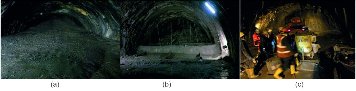 Figure 1: Muck Flow in Seri Nala: a) Face collapse in 2012, b) Concrete barrier to protect further collapse of face, and c) Application of PU grout to stabilize the ground.
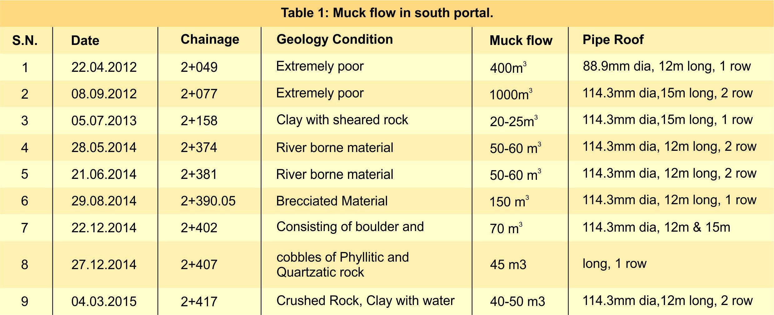
Based on expert's recommendations, various compositions for the tunnel supporting system were tested to address the challenges of arresting the same, while consistently monitoring the situation through probing methods, including Tunnel Seismic Prediction, to assess the state of the rock mass ahead of the face.
Several techniques, such as micropiling to prevent wall collapses, the side drift method to minimize the cross-sectional area, and a pilot tunnel of 5 m in diameter for drainage purposes, were implemented, yet none yielded successful results. The pilot tunnel and side drift method encountered failures within the first 3-4m of excavation, as illustrated in Figure 2. Ultimately, fundamental tunnel construction principles were applied, utilizing a pipe roof system, as depicted in Figure 3, along with partial excavation, which successfully allowed passage across the Seri Nala.
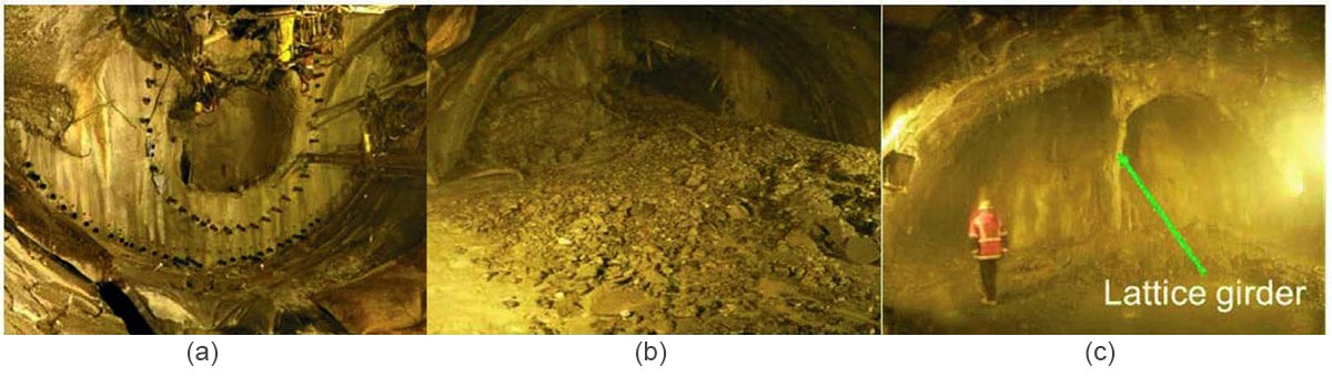 Figure 2: Trials for excavation: a) Pilot tunnel for drainage and reduction of cross-sectional area, b) Collapse of pilot tunnel within 4 m excavation, and c) Side drift method.
Pipe roofing and grouting: To tackle the Seri Nala fault zone and prevent roof collapse, the installation of pipe-roof was started to advance the tunnel safety. The pipe size started at 76.2 mm dia, as given in BOQ but it was collapsing and then was first upsized by 88.9mm and finally to 114.3 mm in single and double rows. Due to the installation of the pipe roof the progress started to stagnate at an average of 10m per month for about four years. Approximately 39km of pipe roofing has been utilized in the Seri Nala fault zone. The P-5 system (Plug, Probe, Pressure Relief, Protection of Roof, and Pre-Grout & Support) has been implemented to address the challenging conditions present in the Seri Nala area.
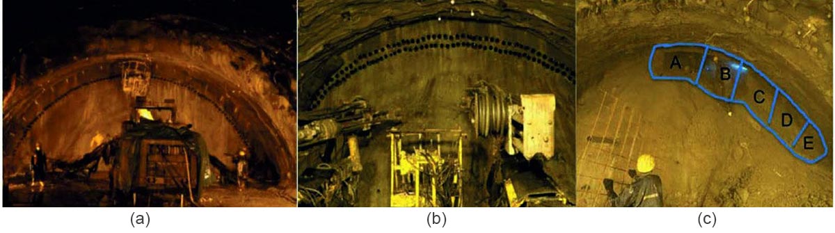 Figure 3: Excavation with ground stabilisation: a) 88.9 mm dia single row pipe roof, b) 114.3 mm dia double row pipe roof, and c) Sequential excavation and support system in fault zone area.
Resourcefulness in planning and solving design challenges:
Following the completion of preliminary work, the primary challenge in the Seri Nala Fault Zone involved re-profiling and excavating the invert section. The section was divided into Heading 2, benching, and the invert. Excavation of Heading 2 was conducted on both sides, with the central portion left unobstructed to facilitate traffic movement.
During the excavation of the benching and invert, a significant logistical challenge emerged in supplying concrete and other essential materials beyond the Seri Nala zone. Approximately 800m3 – 900m3 of concrete, along with steel and additional materials, was required daily, particularly during the winter months when the north portal was inaccessible.
The benching and invert in the Seri Nala section, were designed as a complete circular section, with the invert closed six times after benching rounds. To facilitate material transport, a bridge was required. The original bridge, designed abroad and measuring approximately 100 m, was intended to support excavation, waterproofing, reinforcement, and final lining. However, the manufacturing, erection, and relocation of this bridge proved time-consuming, due to its import from abroad. With the inauguration date approaching, it was decided to deploy two Bailey bridges: one 30 meters long for excavation and primary support, and another of 60 meters long for waterproofing, reinforcement, and final lining of the invert, as illustrated in Figure. 4.
To expedite operations, both ends of the bridges were fixed on rollers, reducing the time required for shifting them 4-5 days to 12-15 hours, as Bailey bridges can be delaunched and relaunched at new locations. This innovation significantly reduced the cycle time of activities, resulting in substantial time and cost savings. The invert shutter for the Seri Nala zone was designed and imported from Germany, with some sections fabricated locally using innovative methods.
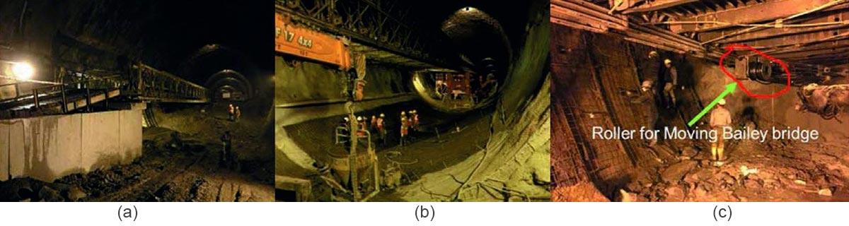 Figure 4: Bailey bridges: a) 30m bailey bridge for invert excavation, b) 60m bailey bridge for waterproofing, installation of drainage system and final lining, and c) roller fitted bailey bridge for shifting of bailey bridge.
Rock bursting: Rock bursting was observed at the north portal, specifically between Chainages 7215 and 7240, on October 13, 2013, as depicted in Figure 5. Prior to the failure, deformations exceeding 300 mm were recorded, significantly surpassing the permissible deformation limit of 40 mm. This incident underscores the principle that natural phenomena often provide precursor signs, and timely intervention can avert adverse outcomes. Subsequent to the collapse, on other sections, gaps were intentionally left in the shotcrete lining. These were intended to be filled once convergence had stabilised, thereby mitigating the issue of delayed shotcrete cracking at the 2 o'clock position.
This approach, however, contradicted the established principle of maintaining a continuous shotcrete lining to ensure comprehensive effectiveness in NATM tunnels. When this situation proved unmanageable, a Lining Stress controller was introduced and demonstrated considerable efficacy in arresting cracks within the shotcrete lining, as illustrated in Figure 5.
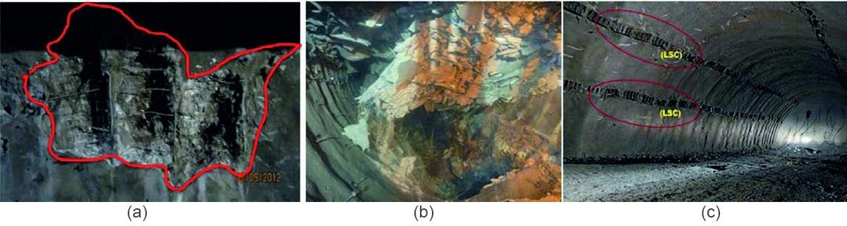 Figure 5: High overburden and competent rock: a) Indication before rock bursting, b) Rock bursting, and c) installation of Lining Stress Controller (LSC).
Case study: Sela Tunnel
The Sela Tunnel in the Western Arunachal Himalaya is dominated by high-grade metamorphic rocks of the Sela Group and metasedimentary rocks of the Dirang Formation, all shaped by intense tectonic activity and the presence of significant thrust faults. This complex geological setting, coupled with high seismic activity, underscores the engineering challenges of the Sela Tunnel. The Sela Tunnel is situated at an elevation of over ~3,962 m, and a few kilometers west of the Sela Pass. The tunnel itself runs at a lower elevation than the Sela Pass at about 4,200 m, allowing it to bypass heavy snowfalls that often close the pass in winter.Challenges faced during construction
The construction of the Sela Tunnel at approximately 4000 m is a monumental engineering feat led by the Border Roads Organisation, which faced extreme environmental and geological hurdles. Engineers experienced freezing temperatures of -10°C, which caused the formation of massive icicles inside the tunnel and delayed the concrete setting process.The project endured roughly 832 days of sub-zero temperatures and 762 days of heavy rain or snowfall, severely limiting the working window. Geologically, the fragile Himalayan terrain led to frequent water ingress and cavity formations, requiring the use of the New Austrian Tunnelling Method (NATM) to stabilize the rock mass. Additionally, progress was hindered by Covid-19 pandemic restrictions, a major cloudburst in 2023 that damaged approach roads, and the logistical challenge of transporting over 71,000 metric tonnes of cement to such a remote, high-altitude location.
Remedial measures adopted
During the construction of the Sela Tunnel, the BRO implemented several remedial measures to overcome the volatile Himalayan geology and extreme weather. To manage fragile rock formations and squeezing zones, engineers utilized NATM, which emphasizes the "build-as-you-go" principle, using the inherent strength of the surrounding rock for support. Specifically, to tackle cavity formation and unstable strata, they employed rock bolting, shotcreting, and forepoling (installing a protective umbrella of steel pipes) to stabilize the tunnel crown before excavation.For the challenge of water ingress and freezing temperatures (reaching -10°C), BRO used advanced waterproofing membranes and permanent dewatering systems to prevent icicle formation and structural damage. Additionally, the inclusion of a parallel escape tube/tunnel with cross-passages every 500 m serves as a vital safety measure for emergency evacuation and ventilation, ensuring the project's long-term resilience against natural calamities.
Case study: Nechiphu Tunnel
The tunnel area is part of the Bomdila formation in West Kameng district of Arunachal Pradesh, India. It is placed between two notable thrust systems: MCT at the top of the structural level to the north and MBT at the lower structural level to the south.The Bomdila Gneiss is highly sheared, and strained, and displays a number of shear-sense indicators. The gneiss rocks are moderately weathered, highly jointed, and fractures are found in the study area. This area lies in Zone V, one of the most seismically active regions. The 450m long Nechiphu Tunnel bypasses the existing BCT road, which remains foggy throughout the year. Visibility is very poor even during the day, and therefore, this stretch is a safety hazard and accident-prone.
Challenges faced
Constructing the Nechiphu Tunnel presented significant engineering hurdles due to its location in the tectonically active Himalayas. The fragile, and highly fractured rock strata created risks of collapse and cavities, requiring the NATM method and constant 3D monitoring for stability. The low overburden (shallow depth) further complicated the process, as the lack of thick overlying rock reduced natural pressure, increasing the risk of surface settlement. Additionally, the area's perpetual fog, with visibility (often dropping to zero) not only necessitated the tunnel to bypass dangerous surface roads but also made logistics and site safety for the BRO exceptionally difficult.Remedial measures adopted
To address the fragile strata and low overburden at the Nechiphu Tunnel, the BRO utilized NATM. This involved strict 3D monitoring and proactive application of a tailored tunnel support system to stabilize the highly fractured rock on a daily basis. To combat the extremely foggy conditions of Nechiphu Pass, the 500 m, D-shaped tunnel was equipped with state-of-the-art electro mechanical systems, including an auto-illumination system and SCADA-controlled monitoring, ensuring safe, all-weather transit for strategic military convoys and civilian traffic.Conclusion
The construction of the Atal Tunnel at Rohtang presented significant engineering challenges, positioning it among the world's most demanding tunnel projects. The difficulties stemmed from severe climatic conditions, challenging geological strata, the presence of an extensive shear zone, and the proximity of an active river flowing overhead.The extensive experience gained from this project is expected to inform future tunnel construction in the Himalayan region, allowing engineers to anticipate and mitigate potential issues during project execution.
The tunnel was constructed using the drill-and-blast method in accordance with the New Austrian Tunnelling Method (NATM) philosophy, which proved to be the most suitable technique for the Himalayan environment, effectively limiting the applicability of Tunnel Boring Machines (TBMs). Owing to the inaccessibility of certain stretches, which restricts detailed geological investigations, the adoption of regular probe drilling or tunnel seismic prediction methods is recommended to better anticipate ground conditions.
Although waterproofing was provided only in the Seri Nala section, seepage has been observed in several other parts of the tunnel, indicating the need for comprehensive waterproofing along the entire tunnel length in future projects.
The successful execution of the project was facilitated by the FIDIC Red Book 1999 contract framework, under which all project risks were borne by the employer. However, future contracts should more clearly define risk allocation by assigning risks to the parties best positioned to manage them.
Given the highly complex and variable geology of the Himalayan region, reliance on a single standardized approach is inappropriate, as each tunnel presents unique challenges that demand customized solutions. Therefore, a flexible and adaptive strategy integrating planning, design, construction, and continuous performance monitoring is essential for the successful delivery of tunnel projects in this geologically diverse environment.
References
- Bhasin, R. K., & Grimstad, E. (2011). Shear Zone Treatment in Tunnels and Foundations. In Engineering Rock Mass Classification (pp. 7-42).
- BRO (Border Roads Organisation). (2024). Sela Tunnel Project: Overcoming the Impossible. Traffic JnfraTech Magazine, March-April Issue.