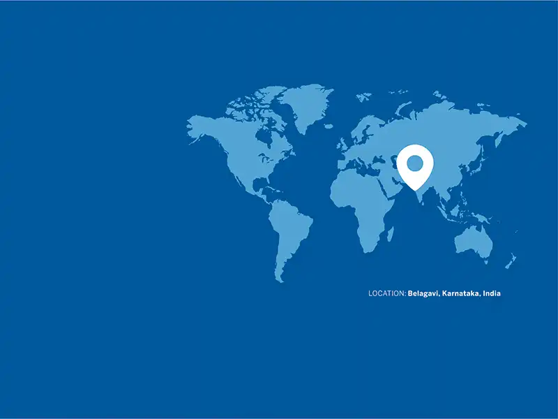
Project: Building a Seismically Resilient Church in the Hills of Nagaland
Blending Faith, Form, and Modern Engineering
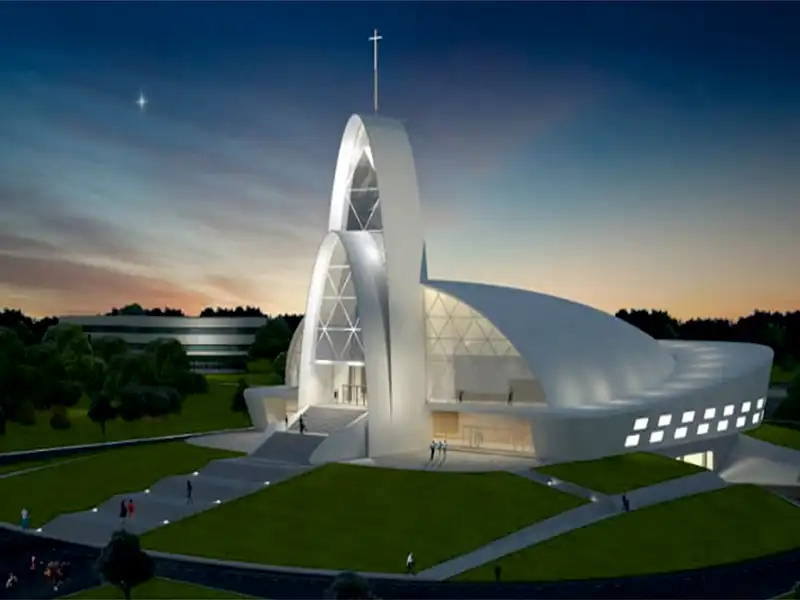
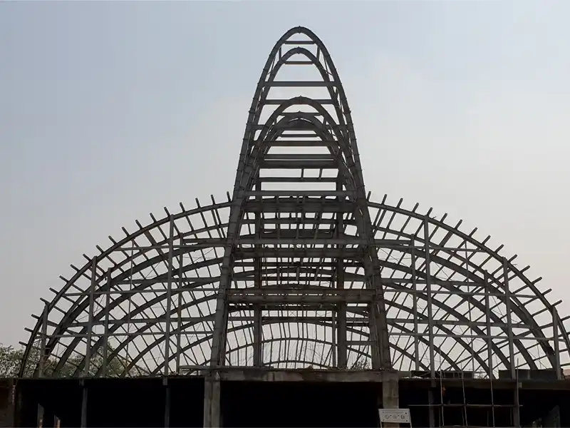
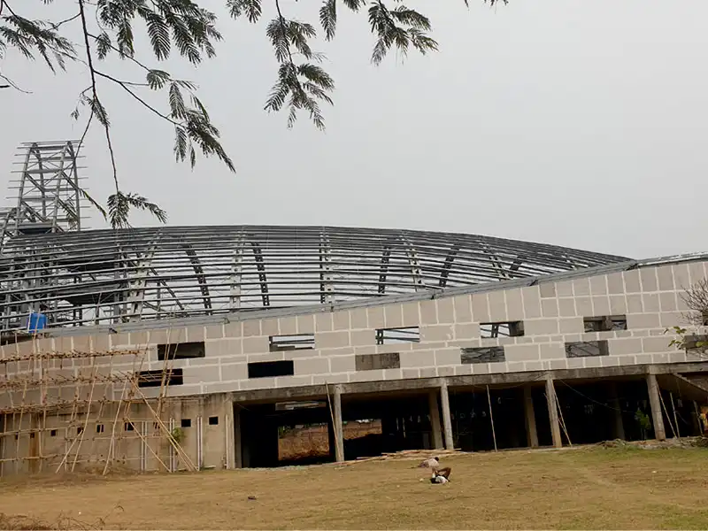
Located in Nagaland, one of India’s most seismically sensitive zones, this monumental church project was engineered for maximum resilience. Use of 600 tons of steel supported over RCC slabs and pedestals, with deck slab flooring, ensured both structural integrity and efficient space utilization.Inspired by the biblical story of Noah’s Ark, and guided by the founder’s vision, this G+1 structure is designed to accommodate up to 5,000 worshippers. Its distinctive curved design reflects a harmonious blend of symbolic architecture and cutting-edge steel construction.
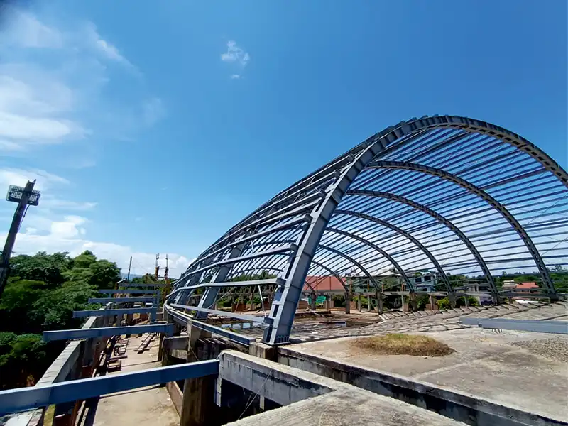
Twin arch towers form a soaring spire (symbolizing spiritual ascent) and anchoring the design. A uniquely curved dome roof, shaped like a vertically sliced half-egg, crowns the structure, and is complemented by tapered sidewalls and staggered windows that evoke the appearance of an ark.
upper level is constructed using structural steel, achieving a 57-meter clear span, with a total length of 87 meters and a height of 18 meters. The expansive main auditorium features a stepped gallery for optimal viewing and houses a 262 sq.m stage for large gatherings and ceremonial events.
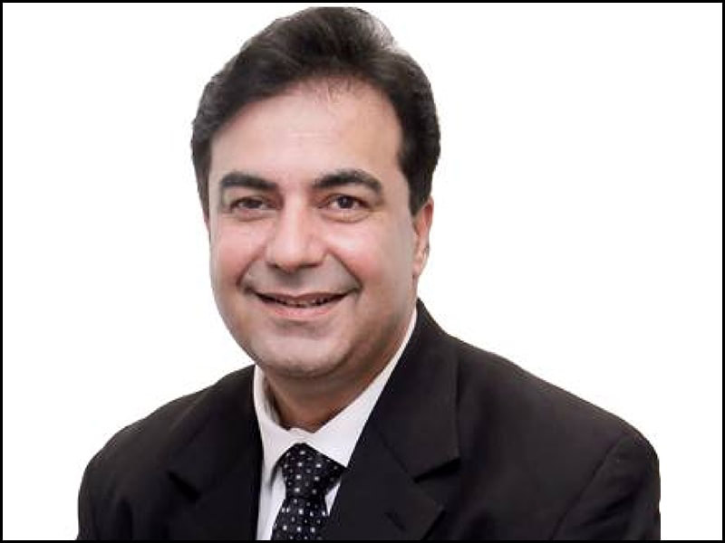
“Digital construction with Tekla Structures resulted in a 30% reduction in rework and significant time savings during assembly, contributing to an overall 10% decrease in project execution time. Tekla Structures played a pivotal role in speeding up production planning, reducing human error, and ensuring complete documentation - all of which contributed to timely and error-free project execution,” said Ravindra Ganamukhi, CEO, ISB Infrastructure
Unique structural & architectural challenges
- Seismic foundation design: Due to the high seismic risk, the building rests on suitably designed footing foundations and plinth beams system/grid to ensure stability and resilience.
- Dome structure: The centerpiece is a massive dome spanning 57 meters wide, 18 meters high, and 65 meters long, designed to resemble a vertically sliced egg - symbolizing rebirth and protection.
- Perimeter corridor: Surrounding the dome is a gradually ascending roof corridor, featuring tapered outer walls and staggered window placements, enhancing both aesthetics and natural lighting.
- Facade design: The front elevation showcases two sweeping curved walls - one in RCC (reinforced concrete) and the other composed of glass, creating a dramatic and transparent entrance.
- Vertical towers: Two prominent vertically elevated towers rise at the front, standing at 28 meters and 36 meters, respectively. These include mezzanine levels that offer functional vertical spaces with architectural contrast.
- Main auditorium and gallery: A 262 sq.m. stage and a curved, stepped gallery ensures clear sightlines and acoustic optimization.
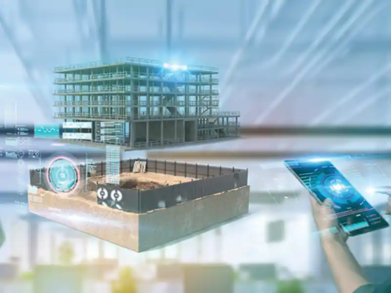
Timely and error-free project execution enabled by Teklabuild
Modelling and design approach
The intuitive and user-friendly interface of Tekla Structures played a vital role in guiding and supporting the project team during the development of this architecturally distinctive and structurally complex building. Its robust modelling environment enabled efficient handling of challenging geometries, resulting in a 20% reduction in modelling time compared to conventional CAD platforms.In the modelling phase, the portal frames within the dome area were developed using Tekla Structures’ advanced column and beam configuration tools. Curved members were generated with ease, requiring minimal input, and reducing manual effort significantly. The multi-window interface allowed for simultaneous views of different model areas, which greatly improved accuracy and speeded up the development of radial frames in alignment with the general arrangement (GA) drawings. This approach contributed to a 25% improvement in modelling efficiency and fewer design coordination issues, leading to smoother integration across disciplines.
Extensive profile library and customization
Efficient modelling and editing tools
Tekla Structures’ fast-editing capabilities - such as fabrication phase lotting, assembly creation, and automatic part numbering - streamlined the entire modelling workflow. The use of customizable keyboard shortcuts accelerated repetitive tasks, resulting in an estimated 20% increase in modelling productivity compared to traditional methods.High-quality detailing and collaborative model sharing
Tekla Structures’ powerful dimensioning and detailing tools produced clear and accurate outputs across general arrangement (GA), assembly, and part drawings. The Tekla Model Sharing platform enabled multiple team members to work on the same model simultaneously, which significantly improved collaboration. This approach led to a 30% reduction in coordination errors and helped maintain consistent drawing quality across disciplines.Standardized predefined components
Tekla in action: bringing experience and confidence
The execution team affirmed that the success of this project has given them a transformative learning experience, revealing the depth and versatility of Tekla Structures. By approaching the work methodically and tackling each phase gradually, the team successfully overcame several technical and logistical challenges. The result was the development of a highly detailed, structurally complex BIM model that met all design and construction requirements.Through this process, the team gained hands-on expertise with advanced modelling techniques, custom automation, and collaborative workflows. This experience not only enhanced their technical proficiency but also led to a notable 35% improvement in modelling efficiency over the course of the project. More importantly, it boosted the team’s confidence and readiness to handle even more technically demanding and larger-scale projects in the future.
Key Tangible Benefits
- 30-40% reduction in time spent on drawing generation and batch-wise documentation
- Eliminated 90% of manual tracking errors in phase-wise material and assembly lists
- Improved batch traceability, leading to 25% faster coordination between design, fabrication, and logistics teams
- Reduced rework incidents by 30% due to segregation and selection of phase-wise components
- Enabled one-click access to phase-wise assemblies for fabrication teams, saving 2–3 hours per batch release
Published on:
12 June 2026
Published in: NBM&CW JUNE 2026
Share:
We Value Your Comment