TCS Campus Siruseri - Chennai

Tata Consultancy Services (TCS) India is building a new $200 million IT Park in Siruseri, Chennai. Designed by Uruguayan architectural firm Carlos Ott Architects in association with Carlos Ponce de León Architects, the project stands as an iconic development in the cyber corridor, distinct in the style, grandeur and aesthetics. Being truly an engineering and architectural marvel, the Techno Park is unique in the way it blends both business and lifestyle statements. It combines elements of traditional Indian architecture with modern design. An aerial view of the complex resembles six butterfly wings intertwined with a central spine.
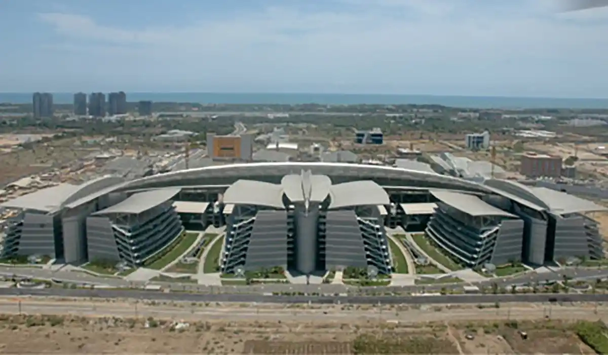

Intelligently-designed, eco- friendly developed, this innovative design demonstrates environment-friendly processes, techniques and systems to meet the requisites for energy-efficient buildings, ISO 14001 certifications, zero waist disposals, carbon footprint offset, etc. The complex is notable for its microclimate performance based on an open atrium office buildings, providing a naturally-ventilated system. An ecological stream beneath a large overhanging canopy of 400m provides a natural cooling system. The Campus has already applied for Leadership in Energy & Environmental Design (LEED) Certification for Platinum and Gold ratings from the US Green Building Council.
![]() |
![]() |
Here in this article, we are presenting a case study on the evolution of the structural system of this project, discussing in particular the analysis and design of the central spine which resembles a 'Giant Wasp.' The paper will also discuss the structural system suitably provided for the huge cantilevers at the ends representing the tail, huge cantilevers at the sides representing the legs and the pyramid shaped lattice girders representing the body of so called giant wasp. Also will discuss about the behavior of central spine structure due to wind here.

Effects of Wind on A3 Dimensional Steel Structure for the Central Corridor Roof
The techno park at Siruseri, Chennai has 6 engineering blocks, customer care center, General services block, Training and library block and other facilities (Figure 1).![]() |
| Figure 1: TCS campus showing central spine |
The central corridor roof between the engineering blocks which is known as the central spine serves as the shelter for people movement. This also houses the landscape which consists of water body and other facilities. The architectural concept is such that 2 giant wasps each of 8 pairs of legs and long tails are facing each other. The formation of the entire structure is by means of 3 dimensional curves. In both the side elevations, it is symmetrical about vertical axis (Figure 2). In top plan, it is symmetrical about both vertical and horizontal axes as in Figure 2.
![]() |
| Figure 2: Views of central spine |
Project team
Architect: Carlos Ott Architects in association with Carlos Ponce de León Architects (Uruguay, South America); Resident architect: CRN architects (Chennai, India); Engineering Services: Potential Service Consultants (Bangalore, India); Review and Project Management Consultants: TCE Consulting Engineers (Bangalore, India)Structural System
Main portals and arch bracings
Main portals are formed by intersecting gothic arches (Figure 3). They are the main supporting elements of the central spine in the vertical direction. They are made of two outer pipes and one inner pipe as shown in Figure 3. These 3 pipes are connected by triangulated web members. They are further connected to the arch bracing members which are provided along the elevation. The outer and inner pipes form cantilever trusses called wings to support the purlins on them.
![]() |
| Figure 3: Main portals with arch bracing |
![]() |
| Figure 4: Middle wings |
Middle wings
To reduce the span of purlins a truss system known as middle wings (Figure 4.) which are quite similar to the top part of main portals, are introduced in between the 2 portals. By this, the span of purlins is reduced to around 11 m which is reasonable. The middle wings are supported by the lattice and box girders running between the 2 main portals.
![]() |
| Figure 5: Lattice girder |
Lattice girder and Tail
![]() |
| Figure 6: Tail of central spine |
Foundation
The two legs of each portal consisting of five pipes (including the arch bracing) are connected to a base plate with required stiffeners. Base plate is further connected to the podium column capital by means of cast-in holding down bolts.
Analysis and Design Data
Loads


Temperature loads and expansion joints
Elongation due to differential temperature is of high importance in long steel buildings. It can be taken care of by either providing expansion joints at an appropriate spacing or designing structural members for the additional moments caused by the temperature. Expansion gap between two structures shall be sufficient to accommodate temperature and shrinkage for effects due to wind. Expansion joints are provided at 2 locations along the length, breaking the whole structure into 3 parts known as Central part (1. no.) and Tail part (2. no.). Central part will have 7 spans. The final configuration of the whole structure is shown in the Figure 7.
![]() |
| Figure 7: Central spine divided into central and tail part with expansion joint |
Materials used
Structural steel confirming to IS: 2062 with minimum yield strength of 310 N/sq.mm is used for all structural members. For expansion joints approved Teflon sheet is provided.
Wind Pressure Computations
Configuration
Figure 8 shows the configuration of the central spine (CS) structure. There are sixteen bays of geometrically similar configuration of diminishing size from centre to ends. Each bay is around 21 m long. At the middle, the width is 35 m and height is 55 m, at the ends the width is 12 m and 18 m height.
![]() |
| Figure 8: Configuration of central spine influencing wind pressure |
The bays are open in the bottom, for example up to a height of 24 m at the centre, above which CS supports six wings symmetrically by the framework, which also supports Louvers (water barrier made of overlapping plates) at the roots of the wings with a porosity of 20%. The Louvers extend below F&L.
Types of wind loads
The following cases have been considered to analyze the structure:
Case 1: Wind from empty position of A to B
Case 2: Wind from the direction of B to A, with A absent.
Wind loads with CS and building B only, wind from position A to B
![]() |
| Figure 9: Overall wind pressure coefficients on portals |
Wind loads with CS and building B only, wind from position B to A

Structural Analysis and Design
The structural analysis is carried out by creating a 3 dimensional space frame model using the commercially available software STRAP VER.11.5 for the load combinations as per IS 800 standards. Line elements are used in the finite element model with rigid nodes. Triangular surfaces were created to idealize the curved surface and pressure loads were applied perpendicular to the surface in the required direction. This method has helped in reducing the time that would have been spent for member load computation and its application on each member. In total, including both central and tail part, the structural model contains about 10,400 nodes, 36,700 members and 61,600 degrees of freedom.Design of structural steel members is done using elastic method as per IS: 800 [2] with relevant allowable stresses. Each member is designed for combined stresses due to axial force, shear force and moments. Sample output for the analysis and design are shown in Table 4.

Conclusion
It is observed that the load combinations involving the wind loads computed using the pressure coefficients shown in figure 9 govern the design of members of the central spine structure. Since the structure is very light, the earthquake forces do not have any influence on the design. For academic purpose, the load combinations including earthquake, wind loads on members, live and dead loads are studied. The deflected shapes of the main portals with some governing load combinations are shown in Figures 10 and 11.![]() |
| Figure 10: Deflected shapes for DL, LL and WL |
![]() |
| Figure 11: Deflected shapes due to DL and WL |
The pipe sizes used for the main portals are 350 mm diameter with thicknesses varying from 22 mm to 16 mm. For the other elements almost all available pipe sizes are used considering the most economical sizes and durability. The joints are connected by full strength butt welds. The thickness of base plate worked out to be between 70 to 80 mm for various portals by suitably providing the stiffener plates. Overall structural steel consumption is around 3000 Tons with a roof sheeting area of around 25,000 square meters. The central spine structure under construction is shown in Figure 12. Completed structure is shown in Figures 13 and 14.
![]() |
| Figure 12: Central Spine under construction |
![]() |
| Figure 13: Central Spine at background of Engineering buildings |
![]() |
| Figure 14: Central Spine Completed |
Acknowledgment
The authors would like to thank structural engineers Mr. B. N. Sridhara, Mr. Sajeev Thomas and Prof. G. N. V. Rao, Department of Aerospace Engineering, Indian Institute of Science, Bangalore for their support and cooperation during the design stage. Authors are also thankful to the project team and clients Tata Consultancy Services Ltd for their cooperation in preparing this paper.References
- IS: 875 (Part 1, 2 and 3) – 1987, Indian Standard- code of practice for design loads (other than Earthquake) for buildings and structures, Bureau of Indian Standards, New Delhi, 1989
- IS: 800 – 1984, Indian Standard- code of practice for steel design, Bureau of Indian Standards, New Delhi, 2002
Acknowledgement
The paper has been reproduced from the proceedings of SDSS 2010 (Stability and Ductility of Steel Structures 2010) with the kind permission from the organizers.MGS Architecture January - February 2011
| < Prev | Next > |
|---|


