Importance of Structural Integrity in Precast Connections
N. Gopalakrishnan, Director, CSIR-Central Building Research Institute, Roorkee, emphasizes the importance of structural integrity of precast connections to enhance the static and cyclic behavior of the joints, and gives reasons for the failure of precast structures.
The efficacy of a precast structure completely relies on the effectiveness of the connections in resisting the applied force. Precast connections are of different types and each type performs differently in terms of strength and ductility. In contrast to the conventional construction, connections are being established at the potential hinge region using bolt, coupler, lap, welding, or anchoring. Also, the use of different materials in different forms make the joint a vulnerable part of the precast structure. The failure of structures due to earthquakes and man-made errors underline the significance of structural integrity in precast connections.
Precast concrete is a versatile and highly compatible mode of construction that has led to its widespread application in buildings. It is composed of concrete (mix of cement, sand, aggregates, admixtures and water) which is cast in the desired shape at a factory or in a casting yard, and then transported to the construction site.
Key advantages of precast concrete construction
Connections are the key consideration in the structural integrity of precast construction, which is an assembly of two or more elements designed to resist the applied forces, while the joint is an interface between two elements in a structure where the forces can be transferred. The failure of the precast connections to meet the above listed functions may lead to structural damage, connection failure, inadequate design, and overall structural failure.
Connections play a vital role in ensuring that there is:
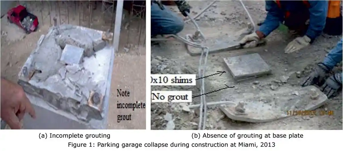
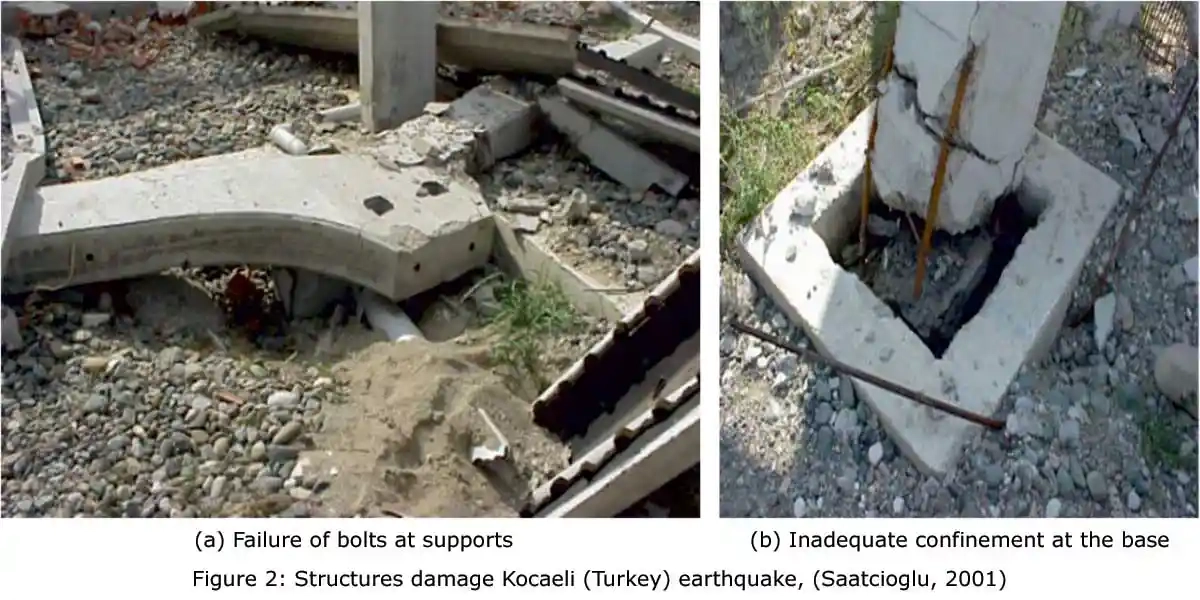
In the parking garage collapse in Miami due to an earthquake, the collapse of column took place in the column-foundation connection due to the absence of grouting and incomplete grouting at the footing under the column (Figure 1). The column base plate was deformed, and bolts were bent into an S-shape. The inadequate confinement in the column led to severe damage at its base (Figure 2). Due to the failure of bolts in the double cantilever head, it led to the entire collapse of the structure (Figure 2). Due to the large lateral drifts at roof levels, the interior columns lost their supports and collapsed. Due to the absence of diaphragm action, the double cantilever to column connection failed and columns failed at mid height.
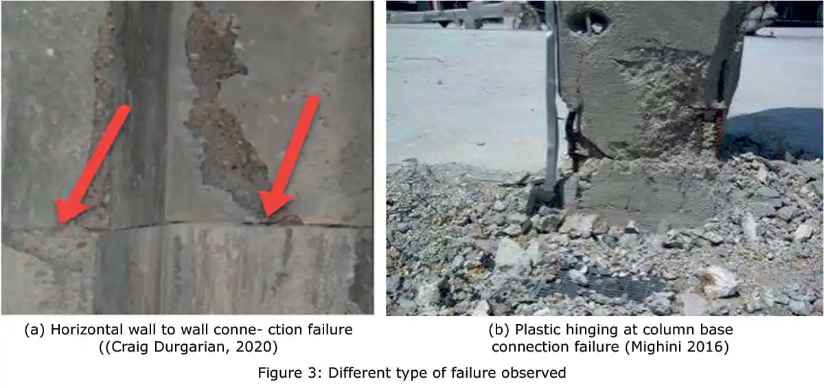
The wall panel joints were filled with non-shrink grout to withstand compressive force. Due to the absence of grout material, it exceeds the capacity of shim plates and led to sudden failure (Figure 3). Due to rotation at the base of the column, it experienced severe plastic hinging with yielding and buckling (Figure 3b).
The partial collapse of the parking structure took place due to flawed construction. There was no grouting done underneath the base plates, which transferred the entire load to anchored nuts. The anchored nuts were unable to take the load, sheared off the nuts so that the columns were tilted, and led to the collapse of the entire structure (Figure 4).

Failure of various structures
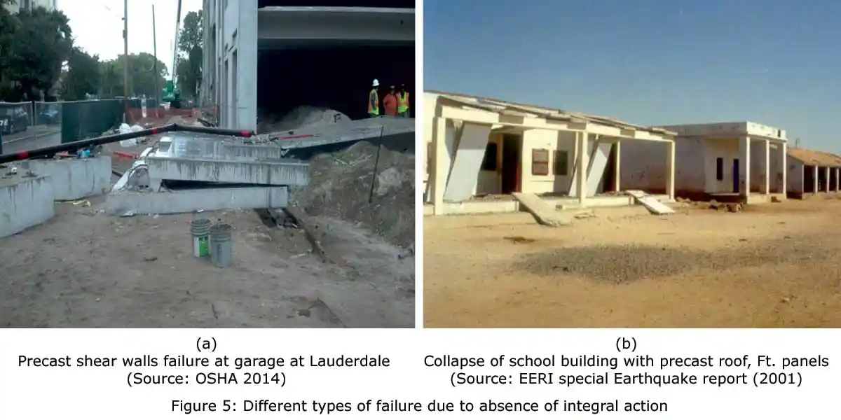
There were many errors in the construction of precast walls at the garage in which the walls were not grouted properly at the shim plates. The shims were not effective in resisting flexural loads, which led to damage of walls (Figure 5a). Due to insufficient seating and fixing of roof panels over the beam and walls, the floor diaphragm action was not adequate, which led to the collapse of the roof panels in the structure (Figure 5b).
All the failure studies emphasis the importance of integral action in transmitting the force and to resist the large drift. Also, the man-made errors such as improper grouting, improper anchoring and inadequate support led the structure to collapse, which makes precast construction more vulnerable as compared to monolithic construction. The structural integrity in terms of connections and joints needs to be ensured for more sustainable and safer precast construction.
Structural Integrity of Corbel Connections (based on research)
Corbel connections are used as beam to column connections or beam to slab connections. It should be designed in a manner that they efficiently transfer all the design forces (Shear, Tension, Compression, Flexure, Bending Moments and Torsion) occurring in the connection zone to ensure structural continuity.
Some of the commonly used corbel connection systems include: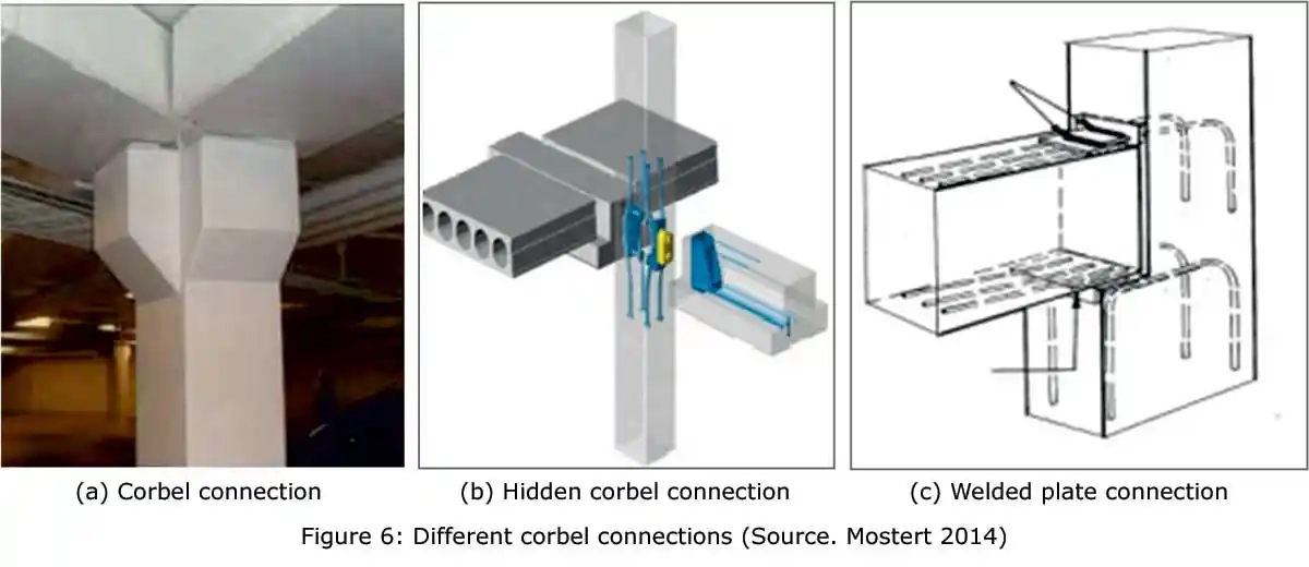
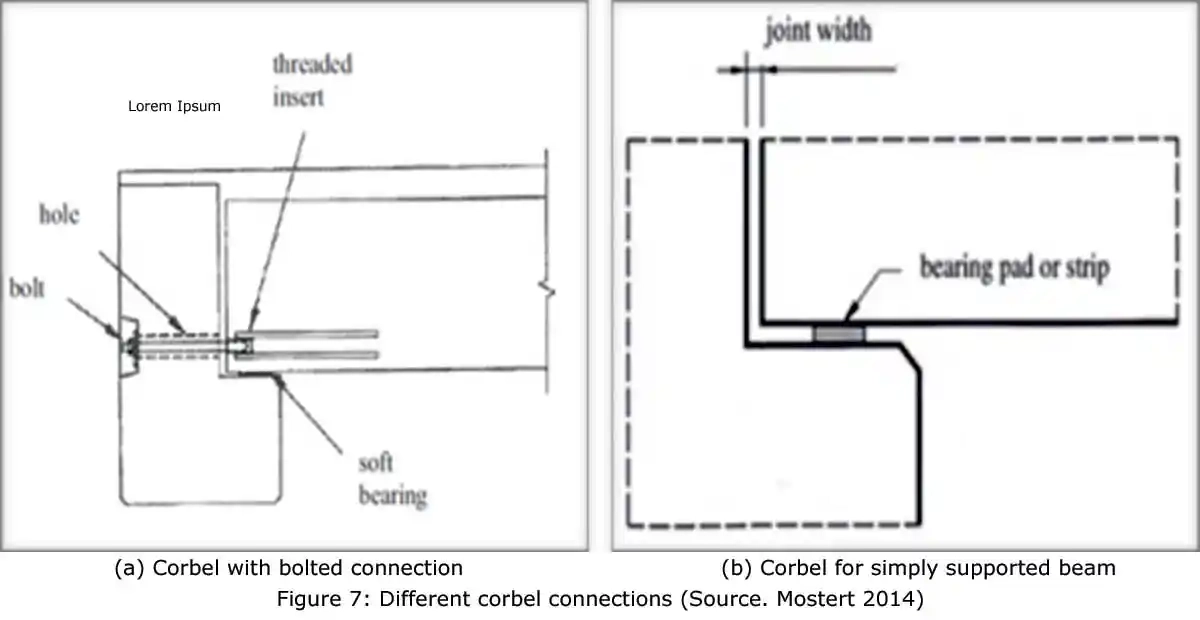
Corbel connection is designed using the strut and tie method and is capable of providing a strong support system in case of large girder installations. However, this connection method leads to a reduction of the headroom at the column head and creates a complex mould requirement. Hidden Corbel Connection has the ability to be highly adjustable at site and can achieve high connection resistance even when applied in slender cross sections. However, it is expensive to install and therefore not very popular in the local industry.
Welded plate connection on a Corbel method constrains the longitudinal forces in the structure, offering a fixed support, and the welded plate can prevent the formation of negative moment at the connection by sliding in the ‘tray’. The downside is the welding requirement at the site and is only possible in case of smaller forces.
In Corbel with Bolted Connection method, the slab is firmly connected to the beam to offer what is considered to be a monolithic system with the beam as part of the floor. The Corbel for Simply Supported Beam connection system is simple and quick to install and is mostly used for flooring purposes. It offers more room for tolerances and has less redundancy with no extra need for special reinforcement. The end supports must however be detailed for crack control and there is need to pay concern for the probable torsional effects and eccentric loading at beam edge.
The common corbel connection is designed to resist only gravity loading. Various research is in progress to increase the load carrying capacity of the corbel connection under various types of loading and in particular seismic loading. To improve the performance, the use of stiffeners, dowel bars and welding in corbel connections has been proposed and experimentally studied by various researchers.
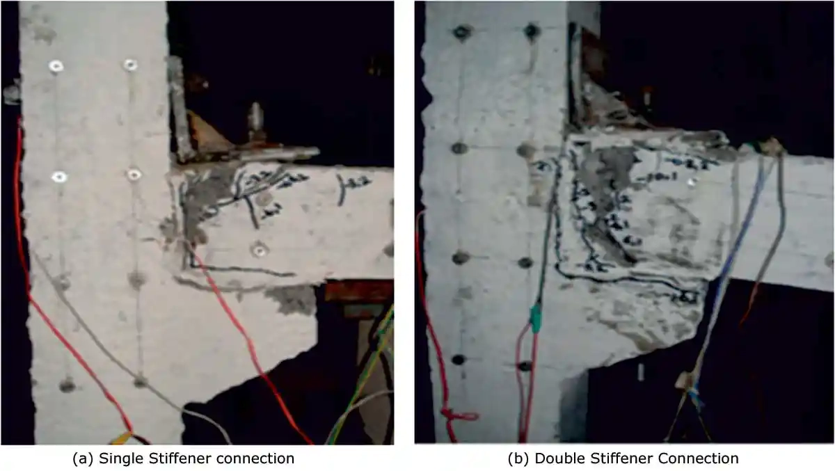
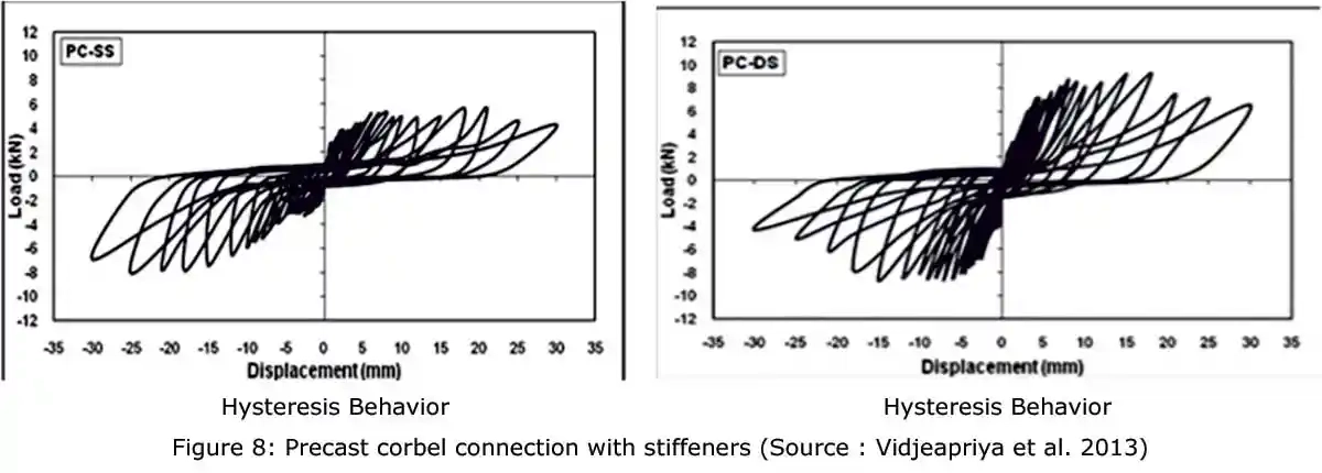
Vidjeapriya et al. (2013) conducted an experimental research on corbel connection with single and double stiffeners. For a corbel column-beam connections with both single stiffener and double stiffeners, the cracks appear at the connection region which is a predetermined crack location at the column-beam interface due to imposed cold joints (Figure 8). For a corbel connection with double stiffeners, the load carrying capacity is more in the positive direction than that of the single stiffener corbel connection (Figure 8). This is due to the increased resistance offered by the double stiffener. The single stiffener connection has more strength in the negative direction as compared to the positive direction due to the location of the stiffener on a single side.
To improve the performance of the corbel-based connections, Sadik et.al (2017) proposed hybrid beam-column connections with welded components using corbel under seismic loading. The beam bottom reinforcement was welded to the beam support plate and a vertical plate was welded to the beam support plate to hold stirrups. The precast beams were placed on both sides of the corbel plate with continuous reinforcement and top concreting was done at site (Figure 9).
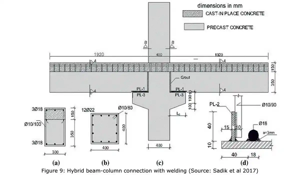
A gap of 7 mm was left between the beam vertical plate and column to fill with proper grouting. It has been observed that there is an enormous increase in the load carrying capacity, stiffness degradation, energy dissipation compared to corbel with stiffeners (Figure 10). The welding had effectively worked in providing the integrity of the connection. In precast specimens, the flexure and shear cracks were observed in the beam and column experienced hairline cracks and rebar buckling. The welded beam longitudinal rebars rupture were seen through visual inspection with concrete spalling.

Inference
The comparison of the hysteresis behavior of different corbel connection shows the influence of structural integrity on the resistance to the lateral load and post yield behavior. The corbel with stiffeners provides better port yield behavior and the same has been elevated to higher level when employed with double stiffeners. Similarly, the welded connection between the base plates of corbel and beam shows tremendous enhancement in terms of energy dissipation and failure patter. It clearly manifests the importance of structural interior of a precast connection offer better resistance to load and to encounter the unwanted failure during erection or due to unexpected loading.
References:This email address is being protected from spambots. You need JavaScript enabled to view it.
The efficacy of a precast structure completely relies on the effectiveness of the connections in resisting the applied force. Precast connections are of different types and each type performs differently in terms of strength and ductility. In contrast to the conventional construction, connections are being established at the potential hinge region using bolt, coupler, lap, welding, or anchoring. Also, the use of different materials in different forms make the joint a vulnerable part of the precast structure. The failure of structures due to earthquakes and man-made errors underline the significance of structural integrity in precast connections.
Precast concrete is a versatile and highly compatible mode of construction that has led to its widespread application in buildings. It is composed of concrete (mix of cement, sand, aggregates, admixtures and water) which is cast in the desired shape at a factory or in a casting yard, and then transported to the construction site.
Key advantages of precast concrete construction
- Safe, speedy, and efficient erection
- Less labor requirement for site installations
- High quality of concrete structural elements due to controlled casting process
- Meets timeliness and availability owing to standardized mass-produced elements
- Applicability in composite construction
- Highly economical.
- Transportation problems due to size and weight of precast members
- Possible occurrence of camber in beams and columns.
Connections are the key consideration in the structural integrity of precast construction, which is an assembly of two or more elements designed to resist the applied forces, while the joint is an interface between two elements in a structure where the forces can be transferred. The failure of the precast connections to meet the above listed functions may lead to structural damage, connection failure, inadequate design, and overall structural failure.
Connections play a vital role in ensuring that there is:
- Overall structural integrity and continuity
- Creation of a monolithic precast or hybrid reinforced concrete structure
- Structural resistance of seismic forces
- Effective force transfer between precast elements
- Overall aesthetic look of the building.
- Ductility: The connection should be capable of deforming to a large extent without failure.
- Strength: Must be capable of resisting any force exerted onto it.
- Fire resistance: To prevent connection failure as a result of fire exposure, the connection should be protected by being sprayed with fire resistance materials.
- Durability: The connections may be exposed and therefore needs to be protected against corrosion by galvanization or use of stainless steel in the connections.
- Volume change: There is a tendency of precast elements to shorten due to combined factors like shrinkage, creep, and temperature reduction. To avoid these, the aforementioned stresses should be accommodated in the design of the precast connections.

In the parking garage collapse in Miami due to an earthquake, the collapse of column took place in the column-foundation connection due to the absence of grouting and incomplete grouting at the footing under the column (Figure 1). The column base plate was deformed, and bolts were bent into an S-shape. The inadequate confinement in the column led to severe damage at its base (Figure 2). Due to the failure of bolts in the double cantilever head, it led to the entire collapse of the structure (Figure 2). Due to the large lateral drifts at roof levels, the interior columns lost their supports and collapsed. Due to the absence of diaphragm action, the double cantilever to column connection failed and columns failed at mid height.

The wall panel joints were filled with non-shrink grout to withstand compressive force. Due to the absence of grout material, it exceeds the capacity of shim plates and led to sudden failure (Figure 3). Due to rotation at the base of the column, it experienced severe plastic hinging with yielding and buckling (Figure 3b).

The partial collapse of the parking structure took place due to flawed construction. There was no grouting done underneath the base plates, which transferred the entire load to anchored nuts. The anchored nuts were unable to take the load, sheared off the nuts so that the columns were tilted, and led to the collapse of the entire structure (Figure 4).

Failure of various structures
There were many errors in the construction of precast walls at the garage in which the walls were not grouted properly at the shim plates. The shims were not effective in resisting flexural loads, which led to damage of walls (Figure 5a). Due to insufficient seating and fixing of roof panels over the beam and walls, the floor diaphragm action was not adequate, which led to the collapse of the roof panels in the structure (Figure 5b).

All the failure studies emphasis the importance of integral action in transmitting the force and to resist the large drift. Also, the man-made errors such as improper grouting, improper anchoring and inadequate support led the structure to collapse, which makes precast construction more vulnerable as compared to monolithic construction. The structural integrity in terms of connections and joints needs to be ensured for more sustainable and safer precast construction.
Structural Integrity of Corbel Connections (based on research)
Corbel connections are used as beam to column connections or beam to slab connections. It should be designed in a manner that they efficiently transfer all the design forces (Shear, Tension, Compression, Flexure, Bending Moments and Torsion) occurring in the connection zone to ensure structural continuity.
Some of the commonly used corbel connection systems include:
- Corbel connection
- Hidden Corbel Connection
- Welded plate connection on a Corbel
- Corbel with Bolted Connection
- Corbel for Simply Supported Beam (Figure 6 & 7).


Corbel connection is designed using the strut and tie method and is capable of providing a strong support system in case of large girder installations. However, this connection method leads to a reduction of the headroom at the column head and creates a complex mould requirement. Hidden Corbel Connection has the ability to be highly adjustable at site and can achieve high connection resistance even when applied in slender cross sections. However, it is expensive to install and therefore not very popular in the local industry.
Welded plate connection on a Corbel method constrains the longitudinal forces in the structure, offering a fixed support, and the welded plate can prevent the formation of negative moment at the connection by sliding in the ‘tray’. The downside is the welding requirement at the site and is only possible in case of smaller forces.
In Corbel with Bolted Connection method, the slab is firmly connected to the beam to offer what is considered to be a monolithic system with the beam as part of the floor. The Corbel for Simply Supported Beam connection system is simple and quick to install and is mostly used for flooring purposes. It offers more room for tolerances and has less redundancy with no extra need for special reinforcement. The end supports must however be detailed for crack control and there is need to pay concern for the probable torsional effects and eccentric loading at beam edge.
The common corbel connection is designed to resist only gravity loading. Various research is in progress to increase the load carrying capacity of the corbel connection under various types of loading and in particular seismic loading. To improve the performance, the use of stiffeners, dowel bars and welding in corbel connections has been proposed and experimentally studied by various researchers.
Vidjeapriya et al. (2013) conducted an experimental research on corbel connection with single and double stiffeners. For a corbel column-beam connections with both single stiffener and double stiffeners, the cracks appear at the connection region which is a predetermined crack location at the column-beam interface due to imposed cold joints (Figure 8). For a corbel connection with double stiffeners, the load carrying capacity is more in the positive direction than that of the single stiffener corbel connection (Figure 8). This is due to the increased resistance offered by the double stiffener. The single stiffener connection has more strength in the negative direction as compared to the positive direction due to the location of the stiffener on a single side.


To improve the performance of the corbel-based connections, Sadik et.al (2017) proposed hybrid beam-column connections with welded components using corbel under seismic loading. The beam bottom reinforcement was welded to the beam support plate and a vertical plate was welded to the beam support plate to hold stirrups. The precast beams were placed on both sides of the corbel plate with continuous reinforcement and top concreting was done at site (Figure 9).

A gap of 7 mm was left between the beam vertical plate and column to fill with proper grouting. It has been observed that there is an enormous increase in the load carrying capacity, stiffness degradation, energy dissipation compared to corbel with stiffeners (Figure 10). The welding had effectively worked in providing the integrity of the connection. In precast specimens, the flexure and shear cracks were observed in the beam and column experienced hairline cracks and rebar buckling. The welded beam longitudinal rebars rupture were seen through visual inspection with concrete spalling.

Inference
The comparison of the hysteresis behavior of different corbel connection shows the influence of structural integrity on the resistance to the lateral load and post yield behavior. The corbel with stiffeners provides better port yield behavior and the same has been elevated to higher level when employed with double stiffeners. Similarly, the welded connection between the base plates of corbel and beam shows tremendous enhancement in terms of energy dissipation and failure patter. It clearly manifests the importance of structural interior of a precast connection offer better resistance to load and to encounter the unwanted failure during erection or due to unexpected loading.
References:
- Elliot, K.S. 2002. Precast Concrete Structures.
- Björn, C. 2006. “Structural Connections for Precast Concrete Buildings”. Paper presented at FIB Guide to good practice. Part 4.
- Ivan Holly, Iyad Abrahoim. “Connections And Joints in Precast Concrete Structures”. Slovak Journal of Civil Engineering. Vol. 28, 2020, No. 1, 49 – 56.
- Louwrens Hubert Mostert, “Design and construction preferences for connections in the precast concrete industry of South Africa”. Master’s Thesis December 2014.
- Investigation of the october 10, 2012 parking garage collapse during construction at MIAMI DADE college, Doral, 2013.
- Saatcioglu, M., Mitchell, D., Tinawi, R., Gardner, N.J., Gillies, A.G., Ghobarah, A., Anderson, D.L. and Lau, D., 2001. The August 17, 1999, Kocaeli (Turkey) earthquake damage to structures. Canadian Journal of Civil Engineering, 28(4), pp.715-737.
- Minghini, F., Ongaretto, E., Ligabue, V., Savoia, M. and Tullini, N., 2016. Observational failure analysis of precast buildings after the 2012 Emilia earthquakes. Earthquakes and Structures, 11(2), pp.327-346.
- R. Vidjeapriya and K. P. Jaya, “Experimental Study on Two Simple Mechanical Precast Beam-Column Connections under Reverse Cyclic Loading”. J. Perform. Constr. Facil., 2013, 27(4): 402-414.
- EERI special Earthquake report (2001), “Primary Observations on the origin and effect s of the January 26, 2001 Bhuj (Gujarat) earthquake”.
- OSHA report (2014), “Investigation of the November 13, 2013 collapse of precast walls at a garage construction site”, Ft. Lauderdale.
- Sadik C.G., Ibrahim S. M., and Serap K. (2017), “Experimental Cyclic Behavior of Precast Hybrid Beam-Column Connections with Welded Components”, International Journal of Concrete Structures and Materials, 1-17.
Concrete Construction April - May 2022


