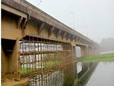
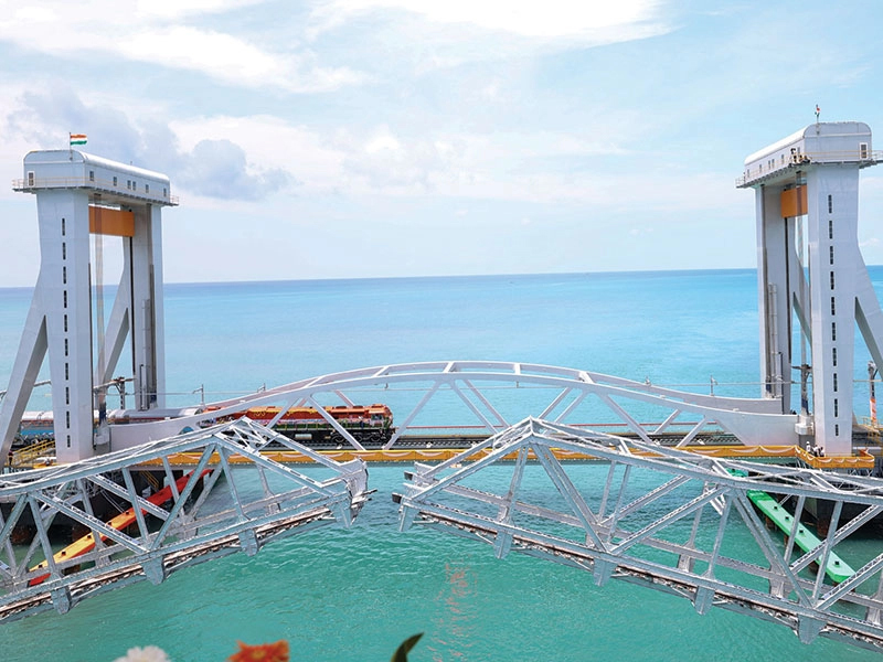
Construction of Precast Aqueduct for Yettinahole Project

The Kolar and Chikkaballapur districts in eastern Karnataka face recurring water scarcity exacerbated by depleted groundwater and contamination from salts like Fluoride and Nitrate. To address this, Karnataka plans to divert excess flood waters during monsoon from Yettinahole, Kadumanehole, Kerihole, and Hongadahalla streams to seven districts, including Hassan, Chikkamagalur, Tumakuru, Chikkaballapur, Kolar, Raman- agara, and Bengaluru Rural, ensuring a sustainable water supply for drinking.
Structural Analysis & Design
Innovatively adopting precast technology, the Yettinahole drinking water project con-structed a 10.47 km long RCC aqueduct with a maximum height of 41m, trough was precast at a gantry yard, while the rest was cast-in-situ, optimizing construction speed, cost-effectiveness, and ensuring durability, and quality compliance with new Indian standards.
The aqueduct structures were designed as per IS Code for Limit State of Collapse (LSC) and Serviceability (SLS), using load combinations specified by IRC:6. Analysis using STAAD Pro and Excel ensured safety against failure and assessed deformation, rotational capacity, crack width, deflections, and static equilibrium. Designs were reviewed and ap-proved by Indian Institute of Science, Bengaluru, ensuring compliance with international standards and structural integrity.

Material Specification
The aqueduct construction employs M40 grade concrete for precast U-Trough, side walls, slabs, and piers, and M30 grade concrete for Pier caps, pedestals, and footings, with reinforcement using Fe-500D grade steel as per IS:1786 standards.
Aqueduct Construction Methodology
The Yettinahole gravity canal's major aqueduct spans 10.47 km from Ch:199.620 km to Ch.210.090 km in Gubbi and Tumakuru talukas, Tumakuru District, designed to convey 93.50 Cumecs via twin troughs measuring 4.75m x 5.15m each with a free board of 1 m. The canal features a trapezoidal cement concrete lining, with hydraulic analysis conducted using Bernoulli's equation and the standard step method validated by HEC-RAS soft-ware (rugosity coefficient n=0.018). The design integrity was reviewed by IISc Bangalore, ensuring adherence to hydraulic parameters and safety standards.
Structural Components
Two rectangular box troughs, each measuring 4.75m x 5.15m internally, are utilized to carry 93.50 cumecs, with the top slab designed for IRC Class-A vehicle loading and featuring a staggered zigzag carriageway. Crash barriers flank the road on either side. Pier caps connect 20m spans supported by pedestals with elastomeric bearings, facilitating place-ment of precast reinforced cement concrete box troughs. Circular piers, varying in diame-ter from 1400mm to 2467mm, are situated on combined footings with a pier connection beam, ensuring structural stability and support.
Foundations are cast-in-situ open footings and pile foundations, adopted as necessary for hard rock strata, with provisions for thermal and creep movements addressed through expansion gaps and IRC:83(Part-11) 2018 compliant elastomeric bearings.

Construction Methodology: Precast Trough Casting
Precast reinforced concrete U-girders were cast at a gantry yard using self-supporting steel shuttering segments, designed for reusability and mechanized production. Self-compacting concrete, adhering to IS 456:2000, was employed for uniform filling and durability, allowing casting in congested reinforcement areas. Girders were de-shuttered within 2 days and lifted with 175MT gantry cranes after 7 days or upon reaching required strength, then moved to stacking yards for curing.
Precast girders are transported on multi-axle trailers upon achieving desired strength, while simultaneous cast-in-situ concrete work progresses for foundations, piers, and pier caps.
Precast girders, handled by 500MT cranes, are smoothly placed on elevated pier caps without requiring temporary stabilization due to their inherent stability. Each girder spans 20m and weighs under 175 MT, ensuring compatibility with available lifting equipment. Following girder placement, the remaining 2/3rd portion of side walls is cast-in-situ using slip form shuttering, progressing at a rate of 20m every two days with the assistance of a traveler system.
The design of the reinforced concrete framed structure, utilizing the working stress metod, includes sub-structures with ties and bracings in both longitudinal and transverse directions. Each pier requires a cycle of 1 week for shuttering and reinforcement placement, followed by a 2-week curing period. Given pier heights of up to 30m, the total construction time for raising each pier is approximately 30 weeks or nearly 7 months.
The superstructure includes ties and bracings along its span, necessitating extensive shuttering and reinforcement laying, which extends the construction cycle beyond the tender period. Therefore, the precast U-trough and other components are designed and constructed to ensure compliance with limit states of collapse and serviceability, facilitating timely completion of the project.
Conclusion
The adoption of Limit State Design with new codes encompasses comprehensive recommendations focusing on design objectives, reliability, strength, safety, serviceability, design service life, and economy. Cast-in-situ activities like foundations, piers, and pier caps operated independently from precast superstructure construction, allowing simultaneous progress to ensure timely project completion.
References
- Ven Te Chow, “Open channel hydraulics,” pp. 265
- N.Krishna Raju, “Design of Bridges,” pp. 49-59.
- GOK, “Yettinahole Project DPR,” pp. 1-555.
- N.Krishna Raju, “Design of Bridges,” pp. 49-59.
- Hitendra chandewar, et al, “Integrated hydraulic design approach for cost effective aq-ueduct trough,” Journal of Civil Engineering Construction Technology, Vol.4(7), PP.224-231, July,2013.