Constraints and Strategic Solutions of Leakage in Chamera Hydroelectric Project (Stage – III)
Virender Salman, General Manager, Kiru Hydro-Elecric Project, Chenab Valley Power Project Limited, Kishtwar, J&K
Achintya, Principal & Professor of Civil Engg., Darbhanga College of Engineering, (Dept. of Sc.& Tech. Bihar), Darbhanga
Introduction
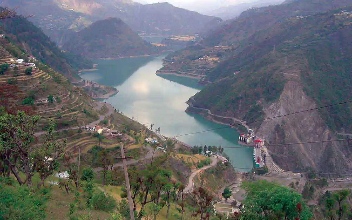
The Chamera Hydro-Electric Project (Stage-III) is located on the river Ravi at village Kharamukh (250.0 m downstream of the confluence of river Ravi and Tundah Nala) in Chamba district of Himachal Pradesh. The Project consists of a 64.0 m high concrete gravity dam across river Ravi. The top level of the dam is at an elevation level (EL) of 1399.0 m with a provision of 3 bays (12.5 m wide and 16.5 m high 3 radial gates) of Gated Spillway and one Chute Spillway at EL of 1382.0 m for a size of 10.0 m width and 15.0 m height. The Full Reservoir Level (FRL) and Mean Draw-Down Level (MDDL) of the reservoir are at EL 1397.0 m and EL 1380.0 m respectively. The gross storage capacity of Chamera (Stage-III) reservoir is 5.48 Mcum at FRL, i.e. EL 1397.0 m whereas the live and dead storage without sedimentation are 3.64 Mcum and 1.84 Mcum respectively.
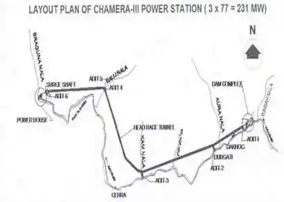 Figure 1: Layout Plan of Chamera III Power Station
Background
During initial filling of water, conductor system leakage was observed and was treated with cement grouting. However, leakage couldn’t be stopped, and the Project was commissioned with the leakage. The leakage increased with the passage of time in the Adit IV plug and spread along the hill slope above aqueduct portion. Dam safety team with experts from Design, Hydro Mechanical, Operation and Maintenance from Corporate office visited twice in a year to check the safety features of the Project; and recommended the following measures to be carried out to reduce the leakage and / or seepage:
- Grouting around upstream abutment of aqueduct needs to be done to reduce seepage, whenever the HRT comes up for maintenance.
- Continue drains, step drains on the switchyard back slope needs to be completed.
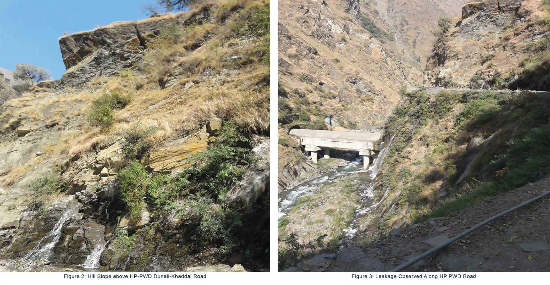
- Hill Slope above Dunali - Khaddal Road: Two cracks were found running at surface level around EL +1365.0 extending deep into the rock strata as shown in Fig. 2. No leakage was observed from the cracks which developed.
- Along the HP PWD Road: Leakage (seepage) was observed at the time of commissioning also in the areas along the HP PWD Road as shown in Fig. 3 and accordingly the area was cement grouted. Rock overall had fractured a lot due to which the area was prone to shooting / rolling stones and causing a few accidents. The frequency of shooting / rolling stones had increased drastically with time.
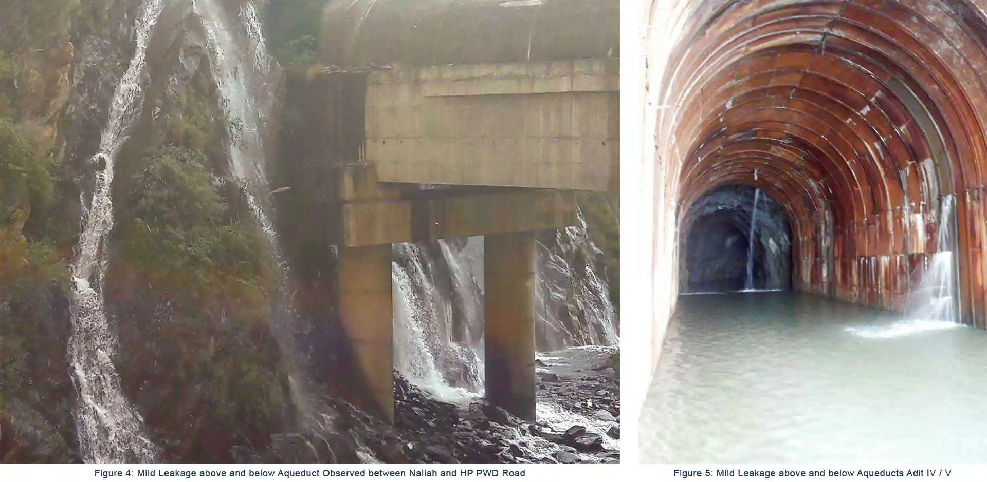
- Area between Nallah and PWD Road (mid leakage above and below Aqueduct): At a number of locations, leakages/fountains of water were noticed (Fig. 4). Heavy leakage was observed from aqueduct and its abutment area and the leakage could not be measured as leakage was scattered and falling directly into the nallah. However, on visual observation, leakage was noticed around +4 cumecs.
Moreover, cracks were observed all-round the hill slope adjoining the aqueduct. Leakage was also observed on the opposite side on the outer face of the aqueduct, i.e., Adit no. V. Leakage was also observed from the plug of Adit IV/Adit V and from the gate of the Plug in Adit IV and at two other places in the Adit IV (Fig. 5). For monitoring purpose as well as for the safety of people and road, the following immediate measures were undertaken:
- Tell tales were installed for monitoring the cracks observed in the agricultural land on the hill slope above HP PWD road. These cracks were filled/ sealed up by concrete to arrest ingress of water and avoid further dislocation and widening of the cracks.
- The cracks in the fractured rock above the HP PWD road were not approachable. However, visual inspection from road was done on a weekly basis.
- Contour drain upstream of the cracked locations on the hill slope above the aqueduct to check ingress of water into the cracks was planned, but the owner of the land did not allow work in the area without paying some compensation.
- Providing of toe protection wall along with permanent drain adjacent to hill slope on the HP PWD Dunali-Khaddal road at the stretch where seepage was observed. Also, concrete was laid on the entire surface of HP PWD road where seepage was coming onto the road from the hill slope. The seepage was to be reduced to protect the road from getting damaged / washed away.
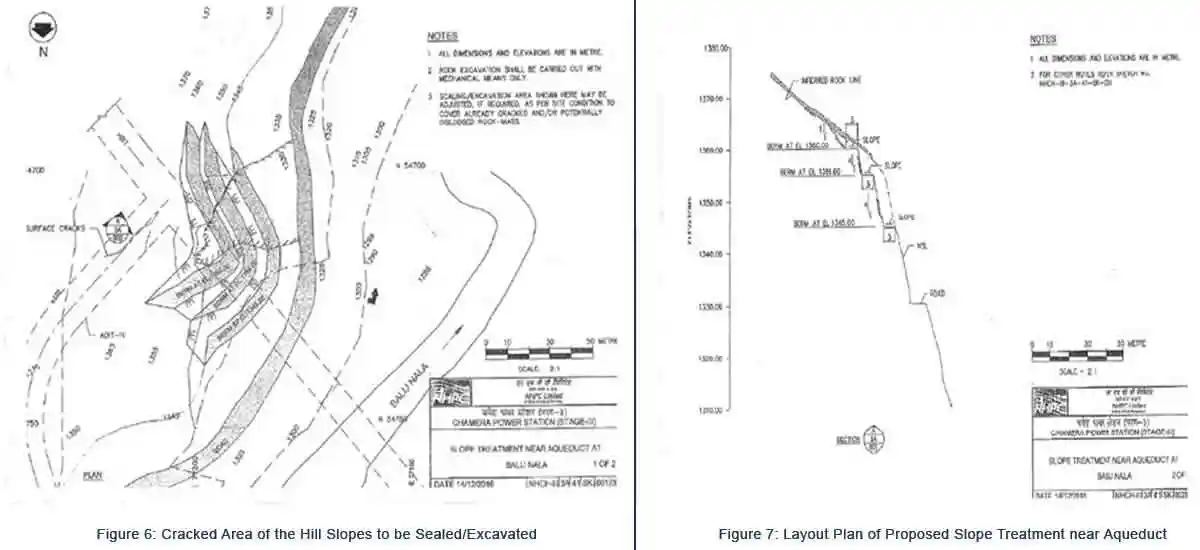
- The cracked area of the hill slopes needs to be sealed/excavated to form berms for slope stabilization above the road level (Fig. 6).
- Repair work of HRT from inside the HRT in the reach to be undertaken forthwith. The repair may involve dewatering (through pump in tough portions), drilling and grouting (consolidation/contact), concreting, sealing the joints/grout holes (Fig. 7).
Generation Loss
For complete shut-down of Power Station from 1st February, 2017 to 30th April, 2017, the generation loss is tabulated as below:
| February 2017 | 9.03 Cr | August 2017 | 59.60 Cr |
| March 2017 | 17.44 Cr | September 2017 | 43.72 Cr |
| April 2017 | 29.40 Cr | October 2017 | 28.76 Cr |
| May 2017 | 56.69 Cr | November 2017 | 90.29 Cr |
| June 2017 | 56.38 Cr | December 2017 | 13.89 Cr |
| July 2017 | 59.09 Cr | January 2018 | 11.20 Cr |
Proposal And Cost
The Power Station framed an estimate in two parts for the repair work of Adit-IV (Part 1 – Works to be taken up inside the tunnel and Part 2 – Works to be taken up from outside the tunnel) for properly grouting of the area and stabilization of slope. Treatment from outside around the aqueduct area was proposed as follows:
- To protect the slope failure of shattered rock and also provide support to the HP PWD road above this area, and also enable internal and external grouting of the area effectively, construction of cladding wall from the toe of the left bank hill slope of the nallah surrounding the aqueduct.
- Grouting of the area below HPPWD road (at EL 1330.0 m) and area surrounding the left bank hill slope of aqueduct.
- Toe protection wall in Adit V (rock fall and leakage observed inside Adit V).
Inside Tunnel
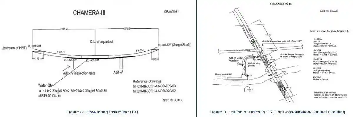
- Dewatering inside the HRT-Estimated quantity 6619 cum (Fig. 8).
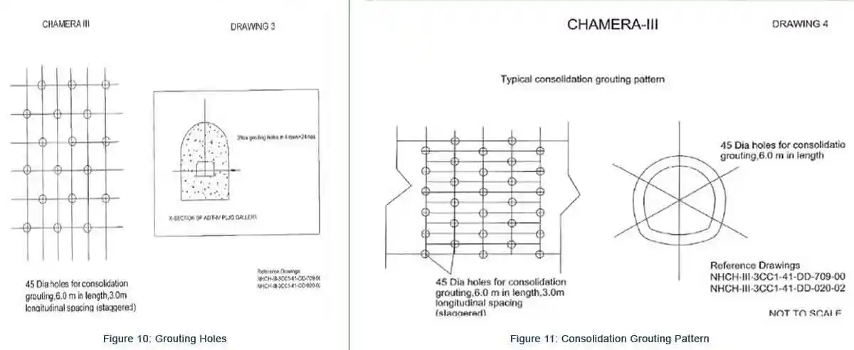
- Drilling of holes in HRT for consolidation/contact grouting (Fig. 9 to Fig. 11) Cement grouting is approximately 836 MT.
- Treatment of joints by chipping/ grooving with fast setting crystalline repair mortar (two layers of 1500 kg each).
- Grout mixture with a composition of cementitious crystalline admixture, cement and fine silica powder in ratio of 1:5:1 (3370 kg).
- Chipping of old concrete wherever necessary and repair with fast setting crystalline repair mortar (1500 kg).
- Providing and laying of cement concrete wherever required.
- Placing of about 6000 sand filled bags.
- Removal of about 4000 bags of slush.
Outside Tunnel
- Rock anchor for cladding wall: Total length = 530 meters
- Cladding wall u/s and d/s and below pier of aqueduct at Adit IV and V side (Fig. 12): Total concrete = 2185 cum.
- Grouting in the area below HP PWD road (Fig. 13) and area surrounding aqueduct at Adit IV side as shown in Fig. 14. Total number of holes = 231.
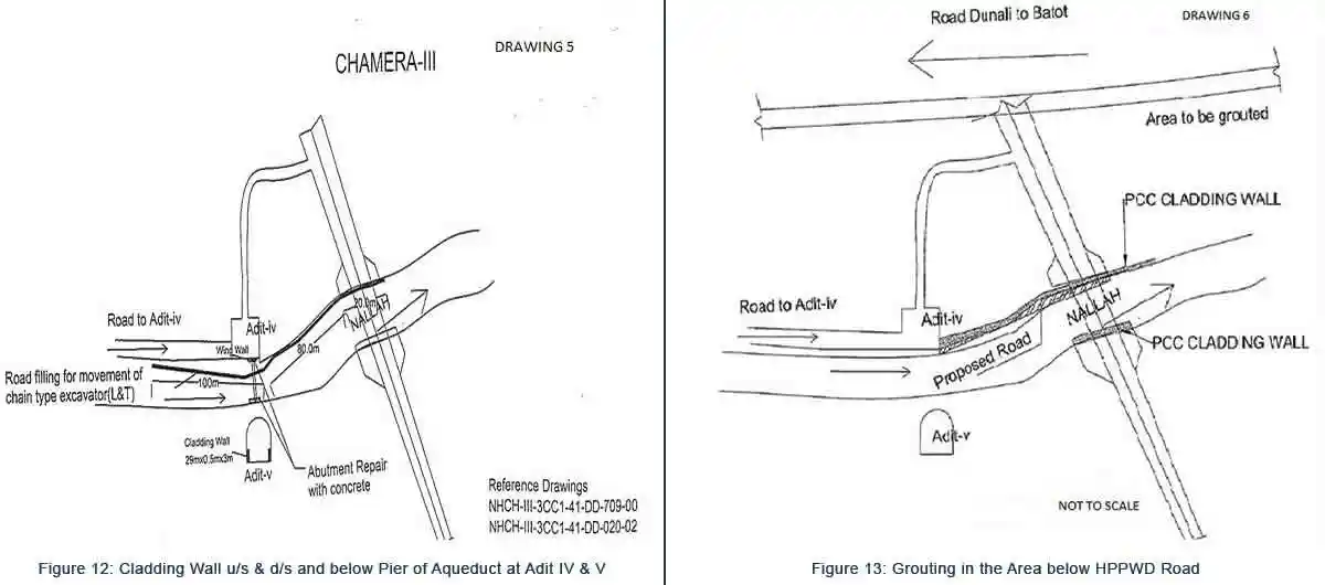
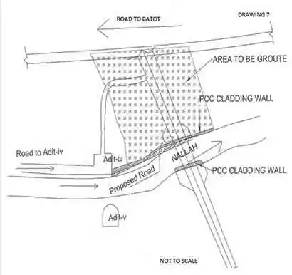 Figure 14: Grouting in the Area Surrounding Aqueduct at Adit IV
Repair Strategy
As very less time was available start of work to see that the tunnel repair is done in minimum time period and in the lean period so that there is minimum generation loss to the power station, day and night working was started with formulation of technology, methodology, planning, estimation, tendering for award of work. Accordingly, the work was tendered and awarded in the shortest time frame. Limited Tender Enquiry (LTE) for repair works inside tunnel in and around the aqueduct at Adit IV was floated among specialized contractors in the area and the work was allotted in the last week of Jan 2017. So, within a period of 40 days, estimation, approvals, tendering, justification and award was done. The following work was awarded for less than 3 crores with working period of 45 days round the clock and just 7.9% above the estimated rates:
- For the safety of the water conductor system, the rate of dewatering needs to be carried out in a controlled manner as per the Reservoir manual. Further, dewatering up to EL 1302.30m is presumed by gravity through seepage and Adit gate valve. This may take more time as dewatering through seepage may not be efficient due to lower/reducing head. For taking up dewatering below EL 1302.30m, dewatering shall be carried out with pumps, therefore, adequate arrangements like man power, pumps, accessories etc would be required.
- The items identified along with their quantities under repair works can be assessed only after inspection and during execution stage as per site requirement. Apart from civil works, repair of steel liner in the aqueduct may also be required, therefore, the agency for cutting/welding, grinding and painting of steel work be kept in parallel to civil works.
- The BOQ in respect of internal works in HRT has been seen and found in order. However, any new item, if required during repair works, shall be advised along with drawings/methodology and technical specifications.
- Repair of concrete lining/backfill concrete cannot be ruled out, Agency with arrangements like concrete breaker, concrete mixture, vibrators etc. along with steel dowels/reinforcement may also be required for such emergent repair works.
- Adit gate rubber seal may also require replacement.
- RCC cladding and grouting on hill slope below road level has also been recommended by RO (Banikhet) as proposal no. 2. The treatment for this area shall be conveyed separately along with the treatment of hill slope above road.
- The total time proposed by the power station for the repair works was 83 days starting from 01-02-2017. The shutdown of the Power Station was taken for 59 days for completion of works and with minimum loss of generation.
- Before shut down, power generation shall be done up to reservoir at MDDL (considering water level in surge shaft is also lowered up to EL 1380.0 m), subsequently intake gates shall be closed.
- Dewatering up to tunnel invert EL 1348.50m (entire HRT & S Shaft) and pressure shaft up to EL 1311m will be done with the help of bye pass valve/machine/SFT which will take around 7 days (considering rate of dewatering @0.4m/hr)
- Dewatering of Adit-6B shall be carried out between EL 1315.50 to EL 1312.38m to access the Adit gate. (required time is estimated at around 8 hrs)
- Dewatering between EL 1318.5m to EL 1300.0 (HRT up to deepest point at Balij nallah) will be done by submersible pumps. The pumps will be installed at EL 1318.5 discharging into P/s or through adit-6B. Estimated time is 2 days.
- As per reservoir filling manual, the rate of emptying shall be slower than rate of filling.
- Dewatering below EL 1318.50m shall be carried out with dewatering pumps. Required maximum capacity of pump is 250HP, number of pumps for dewatering along with standby arrangement may be worked out accordingly.
- Time required for opening of Adit gate, transportation, installation of pumps & machinery, shifting of pumps and accessories is to be considered separately.
Repair of HRT from Adit-4 plug as per scope of work awarded comprises of 100m u/s from Adit-4, area from Adit-4 to u/s face of steel line and up to 50m towards d/s from the d/s face of steel liner along with drilling and grouting of adit-4. The status is as under:
Upstream of Adit-4 plug
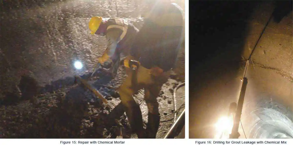
- The gantry joints, curb joints and cracks of concrete lining were repaired with chemical mortar (Fig. 15).
- Total 65 holes were drilled in this zone. On the basis of grouting behaviour and grouting response, the holes were not drilled in the regular pattern and were selected as per site requirement. However, drilling at crown was done at 3m spacing.
- The grout intake was not uniform. Noticeable grout intake was observed at certain locations like at RD 24m (253 bags), RD 38m (293 bags) and RD 63m (291 bags). In other holes grout intake was either negligible/no intake or choked due to grout travelled from the adjoining holes. Around 1100 bags of cement consumed in grouting.
- On completion of joint treatment and grouting in this zone, 3 number of test holes were drilled at RD 6.5m, RD 33m and RD 50m and grout intake was 37 bags, 180 bags and 11 bags, respectively.
- During grouting in this zone, grout leakage was observed from the gantry joints which were sealed with chemical mix (Fig. 16). Some patches in the lining remained moist with few clean water droplets in overt. However, there was no change in these areas during grouting of test holes. No grout/water leakage appeared from Adit and hill slope.
Adit-4 plug to u/s face of steel liner
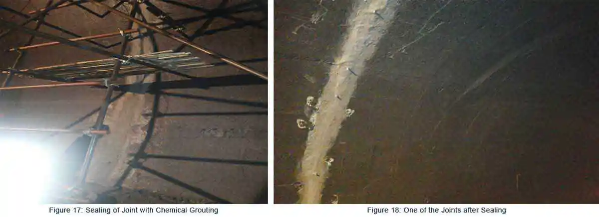
- This zone was found critical and was identified the main source of leakage taking place from Adit-4 plug and aqueduct (left bank) as shown in Fig. 17. Around 65 holes were drilled in this zone which includes around 30 holes within 2m from the liner face. Apart from regular holes, out of two layers as proposed by the design team, one layer close to steel liner face was also drilled and grouted.
- The second stage concrete around Adit-4 gate was found hollow which was connecting the inside water body to d/s face of Adit gate and also the pressure relief holes in the gallery. Expansion joint u/s of Adit gate was also open and it is understood that this could also be the source of leakage.
- A cavity above Adit-4 gate plug was identified just above the plug. This could be corroborated with sudden sinking of drilling rod during drilling. Few holes were attempted in this zone after grouting of first hole. Drilling could be continued for more than 2m due to filled thick grout as the ROC bit could not rotate effectively for further drilling.
- A good quantity of grout intake (around 1800 bags) was consumed during grouting in the plug crown between ± 1.0 m zone with respect to the centre line of Adit-4 plug (designated as RD 0.0m). Prior to taking up the grouting activity in this zone, the expansion joint in concrete on u/s of Adit gate and cavity in second stage concrete got repaired. Grouting was done with slow rate. During grouting moisture appeared at ceiling on d/s of Adit gate followed by clean water droplets. Subsequently, after around 50 bags of grout intake, leakage of grout was observed from the inspection gallery followed by leakage from the d/s face of Adit-4 (around 5m away from the Adit plug face). The leakage points in the inspection gallery were sealed as shown in Fig. 18. However, leakage from the d/s face of Adit plug from concrete and rock interface stopped with time.
- It was observed that grout intake in hill side holes i.e. left wall of tunnel were either negligible or no intake.
- On the right sidewall between d/s RD 2.0m to 16.0m (d/s of Adit plug), 30 holes were drilled. Grout intake was 5 bags to 20 bags only, however, at RD 11.0m around 600 bags were consumed till refusal. There was no leakage towards Adit side as well as in the nallah hill slope.
Steel Liner and RCC joint Area
The most vulnerable area was identified at upstream face of steel liner and RCC joint up to 2.0m zone. Following is the status:
- The steel liner and RCC joint was found detached at crown. It was observed that around 1.0m to 1.5m deep crack developed at the crown.
- Side cracks and bottom crack developed were around 100mm to 150mm deep. At the bottom, a steel pipe of diameter 100mm laid in invert during construction was open to d/s face of aqueduct connecting the inside water body to open air in aqueduct side.
- Initially, the 100mm dia. pipe laid at invert was plugged from d/s side, grouted with mortar and later on, the mouth was capped with MS plate welded at its mouth. The invert joint and side joints were washed, and loose material was removed and the entire joint along the periphery was filled with chemical mix. 3 pipes 1.0m to 1.5m deep inside the joint were embedded at crown and either side of crown for subsequent grouting of joint.
- After 12 hours of joint treatment, grouting was started from one of the right-side grouting pipe placed in the crown. Initially, after consuming around 200 bags of cement, there was no leakage observed from inside and outside. After 2 hours of grouting, leakage was observed in the aqueduct side from the concrete lift joints and concrete steel liner joint which were sealed with cement slurry. In the next 4 hours, slight seepage observed at 3 locations from the rock joints on the left bank nallah bed which was sealed by stacking of cement and river bed material filled bags. After sealing d/s area, slight grout leakage was observed from inside at the steel liner and RCC joint which travelled along the whole periphery and finally started leakage from the other two pipes already left at crown during joint treatment. A total of 1085 bags consumed in this hole with minor wastage on account of leakage. Considering the grouting behaviour as above it is understood that the entire joint was well packed. Grout intake in other two pipes left out during joint treatment was nil.
- Further, holes in radial direction vis-à-vis along the flow fanning outside near steel liner joint were drilled along the periphery but there was no grout intake. This corroborates the sealing of steel liner and RCC joint.
- The rock mass on d/s face (left abutment of aqueduct adit-4) was seen fractured along with tearing of RCC supporting wall. However, no damage observed on u/s RCC wall and rock mass (along nallah flow). One vertical crack appeared on the steel liner supporting end beam in aqueduct area which travelled around 2.0m in the bottom slab. It appears that some rock movement has taken place on d/s of aqueduct which resulted in widening of steel liner and RCC joint from inside the tunnel.
- The concrete around steel liner was sound, well bonded with steel liner and hard in chipping.
- In order to consolidate the area around the steel liner, number of attempts was made. This became a challenging task as each grout hole at crown (RD 17.25m) used to connect directly with rock joints and significant leakage appeared from the aqueduct and rock joints near nallah bed. Interestingly all leakage was observed on d/s of aqueduct (along nallah flow). More than 3000 bags of cement were injected from inside. Initially lot of seepage observed from the fractured joints of RCC abutment wall in aqueduct area which was continuously filled back with mortar/grout/dry cement. Initially leakage was observed but after consuming around 900 bags, the abutment area was well packed and no further leakage observed in the aqueduct area. However, the seepage from nallah bed continued to great extent.
- The rock joints in nallah bed were continuously treated with river bed material filled bags/masonry wall/dry cement/chemical plug. This exercise could succeed to control the seepage to great extent but failed to completely stop the leakage as such the grout hole remained active.
- The above problem encountered around 2.0m u/s of steel liner face (RD 17.25m) taken RD 0.0m as central line of Adit-4 plug. Some of the holes accidently got choked. In order to seal the major crack joint, 8 no. holes were drilled at this location. Surprisingly the holes drilled towards left face of tunnel (from inside) there was no grout intake. To identify the rock joint two holes 2.0m and 4.0m depth were drilled at crown but there was no grout intake which showed no cracks/open joints with 4.0m periphery. Careful observation of drilling activity also indicated that an open joint connecting to nallah bed may exist beyond 5.0m depth.
- In view of open joint lying behind the liner joint, grouting with normal mix was carried out intermittently but to no avail. Further, thick grout with water cement mix of 0.6:1 to 0.4:1 was injected through grout holes. A little success was achieved in terms of grout consistency as grout consistency at outlet point in nallah bed was thinner than the grout consistency being injected at the inlet.
- Finally, sand cement mix grout was adopted with a different suitable grout pump and as a result the active hole could be sealed. Total 222 bags of cement and 48 bags of sand used till grout rejection/completion of hole. After introducing cement sand mix leakage stopped from the rock joints at the nallah.
- On successful packing of above hole, another hole was drilled in the closed vicinity of the completed hole. Water test confirmed possibility of grout intake. Little water appeared from the rock joints on the d/s of aqueduct near nallah bed. Grouting in this hole started with thick cement grout of 0.5:1 (water: cement) till 20 bags of cement than cement sand mix was injected and successfully sealed the rock joint. Total consumption of cement and sand bags in this hole was 45 and 11 respectively. No grout leakage was observed in nallah bed. This activity was also witnessed by the Design Team comprising of GM (Design) and GM (Geology).
- Being critical zone, as advised by the Design Team, again two holes each of 6m depth were also drilled in this zone on either side of crown. Grout intake in these two holes was nil. In view of above attempts, successful grouting with cement sand mix and ‘Nil’ grout in the last two holes, it was concluded that the area is well packed with grout.
- A hole drilled in the invert consumed only 10 bags of cement.
- The concrete behind the steel liner was too hard and well bonded, making of uniform groove surface behind the steel liner for placing hydrophilic rod and placing it uniformly along the steel liner was not found feasible hence abandoned.
- Invert was found slightly damaged at two places near steel liner face and near Adit plug which was repaired with chemical mortar.
- In order to consolidate the plug area as well as to fill the cavity/joint, if any, 5 no. drill holes as suggested by GM (Design) and GM (Geology) were drilled from outside the plug at the crown inclined at 45 degree towards hill. There was no grout intake in these holes.
- 50m length of HRT was proposed for repair.
- Total 9 no. of holes each of 6m depth were drilled at crown. First hole was drilled 3.0m away from the d/s face of steel line and thereafter spacing was kept at 6m.
- Grout intake in crown holes was nil in first two holes i.e. up to 9m d/s from liner joint. In the third hole only 60 bags consumed. 4th hole (21m from steel liner) again grout intake was nil. Grouting work in progress at the site (Fig. 19). During grouting a minor seepage observed from the lift joints and steel liner/concrete interface from aqueduct side which was automatically stopped.
- At 5th hole (i.e. 7.0 m from steel liner face), 1369 bags were consumed. Grout intake remained continue. There was no leakage from inside and outside. Keeping in view the cement bags already injected in the grout hole, it was opined to stop continuing further grouting of this hole.
- Next hole (i.e. the 6th hole) showed no intake.
- In the 7th hole (i.e. 39.0 m from steel liner), 518 bags of cement consumed. This hole was grouted till refusal. During grouting in this area there was no leakage from the adit-5 plug, however negligible grout/water appeared in the Adit-5 wall which was closed subsequently.
- The next two holes could not be grouted as the holes got choked with cement grouting done at the 7th hole.
- After grouting crown holes, further drilling was carried out at spring level. Such holes at 1st row consumed 40 bags. While grouting at this location, air bubbles observed followed by minor grout leakage from the peripheral joint of steel liner and RCC which itself closed after few minutes. This indicates filling of minor gap between steel liner and RCC joint.
- Further holes drilled at spring level up to 15.0 m from the liner and attempted for grouting but there was no grout intake. Also grouting from inside at adit-5 plug area no grout intake was observed. In view of nil grout intake further drilling and grouting at spring level was discontinued. The area of the plug was also well treated with chemical filling at lift joints.
- 3 no. holes each of 4m deep were drilled at crown inclined at 45 degrees along the flow at steel liner joint and one 6m deep hole drilled in the invert. No grout intake observed in these holes.
- It is pertinent to mention that the joint of steel liner and RCC was found sound, intact and there was no damage in concrete. As such it was opined not to dismantle the concrete for placing the hydrophilic rod and fill back with chemical mortar.
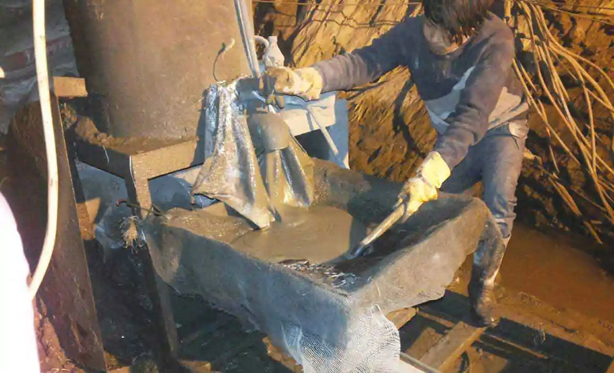 Figure 19: Grouting Work in Progress
In the grouting activity, the grout mix ratio of water and cement was generally kept as 1:1 and 0.8:1. However, near liner, the thicker grout mix was also used varying from 0.6:1 to 0.35:1 along with cement sand mix. The grout pressure was generally varied from 3-5 kg/cm². For thicker mix grout pressure raised u pto 5 kg/cm². Nevertheless, for cement sand mix grout, was injected with a pressure of 7-8 kg/cm². Finally, all the grout holes and previous holes left out during construction were duly packed with chemical mortar. On completion of inside works, the invert area was cleaned.
Apart from above repair works from inside the tunnel, concrete wall placed at toe on d/s of adit-4 portal. Further concrete gravity wall is also being raised in steps starting from nallah bed and shall be raised up to top of aqueduct to support the left abutment of adit-4 aqueduct as suggested by Design Team. Further, as advised by the Design Team, the crack in the hill above the road level, is also being filled with grout. The gate seal was replaced with new one, all the pipes provided for pressure gauge, valves etc. were checked, got necessary welding and finally the adit-4 gate was closed on the intervening night of 28-29 March 2017.
Conclusion
The Power Station is running continuously in very good condition since then and no leakage has been observed till date. The Power generation done by the project is as follows:
| Year (FY) Apr-Mar | Power Generation in MU | Remarks |
| 2012-13 | 716 | |
| 2013-14 | 938 | |
| 2014-15 | 1021 | |
| 2015-16 | 1044 | |
| 2016-17 | 917 | Repair Work done in Feb-Mar 2017 |
| 2017-18 | 1108 | Power Generation has increased by 20.8% |
Published on:
10 October 2019
Published in: NBM&CW October 2019
Share:
We Value Your Comment