
Most of the provisions in the Indian code, IS 456:2000, are based on the experimental investigations on concrete with strengths less than M40. Hence, recently, new equations for the shear strength of RC beams have been proposed for the next revision of IS 456. These equations and their implications in actual design are presented after a brief presentation of the behaviour of beams in shear and comparable provisions in other few notable international codes. A case study of the failure due to inadequate shear design is also provided.
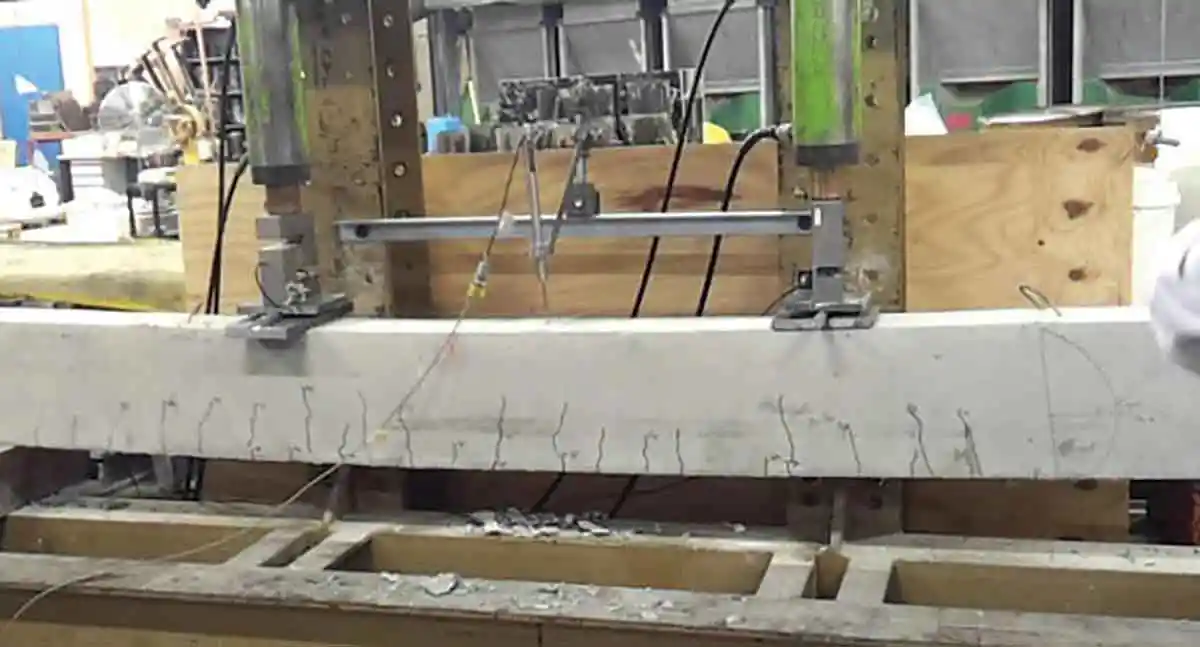
Dr. N. Subramanian
The shear behaviour of reinforced beams has been researched for more than a century and the foundations of knowledge on shear were provided by Mörch in 1909. Reinforced concrete is a composite material and shows non isotropic mechanical properties, which complicates the formulation of relationships between stresses and strains in the material. Hence, the design recommendations of several codes of practice are based on empirical relations derived from laboratory tests. It has to be noted that in many situations, we are concerned with diagonal tension stress, which is a result of the combination of flexural and shear stress. Hence shear failure is often termed as diagonal tension failure. There may be certain circumstances where consideration of direct shear is important. One such example is in the design of composite members combining precast beams and cast in place to slabs, where horizontal shear stresses at the interface between beam and slab have to be considered. As it is inappropriate to use methods developed for diagonal tension in such cases, we have to resort to the shear-friction concept, which is not yet available in IS 456 (Subramanian, 2020).
It is well known that inadequate shear design is inherently more dangerous than inadequate flexural design, since shear failures are sudden and normally exhibit fewer significant signs of distress and warnings than flexural failures. However, unlike flexural design for which the classical beam theory (“plane sections remain plane”) allows for an accurate, rational and simple design for both uncracked and cracked members, the determination of shear strength of reinforced concrete members is based on several assumptions, all of which are not yet proved to be correct. It is important to realize that there is a considerable disagreement in the research community about the factors that most influence shear capacity.
The main objective of RC designer is to produce ductile behaviour in members, such that ample warning is provided before failure. To achieve this goal, RC beams are often provided with shear reinforcement. Also codes are usually more conservative with regard to shear (by providing larger safety factors) compared to bending (for example in the ACI code, a strength reduction factor of 0.75 is used for shear compared to 0.9 used for flexure-tension controlled). Thus, the design methods and detailing rules prescribed in the codes will result in a strength that is governed by bending failure rather than shear failure, if the member is overloaded.
Although the Indian code on reinforced concrete IS 456 was revised in 2000, only the durability provisions of the code were modified extensively. The design provisions were largely unchanged from the earlier 1978 version. Moreover, most of the provisions in the Indian code, IS 456:2000, are based on the experimental investigations on concrete with strengths less than M40. Hence, recently, new equations for the shear strength of RC beams have been proposed for the next revision of IS 456 (Sahoo, 2020). These equations and their implications in actual design are presented after a brief presentation of the behaviour of beams in shear and comparable provisions in other few notable international codes.
Behaviour of Beams in Shear
The mechanism of the brittle type diagonal tensile failure of RC beams with no shear reinforcement (stirrups) is complex and not yet fully understood. The behaviour of beams failing in shear may vary widely, depending on the av/d ratio (shear span to effective depth ratio) and the amount of web reinforcement. In very short shear spans, with av/d ranging from 0 to 1, develop inclined cracks joining the load and the support. These cracks, in effect, change the behaviour from beam action to arch action. Such beams with av/d ratio of 0 to1 are termed as deep beams. Beams with av/d ranging from 1 to 2.5, develop inclined cracks and after some internal redistribution of forces, carry some additional loads due to arch action, These beams may fail by splitting failure, bond failure, shear tension or shear compression failure (see Fig. 1).

In slender shear spans, having av/d ratio in the range of 2.5 to 6, the crack pattern will be as shown in Fig. 1(a) and (b). When the load is applied and gradually increased, flexural cracks appear in the mid-span of beams which are more or less vertical in nature. With further increase of load, inclined shear cracks develop in the beams, at about 1.5d-2d distance from the support, which are sometimes called primary shear cracks (Subramanian, 2013). The typical cracking in the slender beams without transverse reinforcement, leading to the failure involves two branches. The first branch is slightly inclined shear crack, with typical height of the flexural crack. The second branch of the crack, also called secondary shear crack or critical crack, initiates from the tip of the first crack at relatively flatter angle, splitting the concrete in the compression zone. It is followed by a tensile splitting crack (destruction of the bond between steel reinforcement and concrete near the zone of support), as shown in Fig. 1(a). Depending on some geometric parameters of the beam, the critical crack further extends in the compression zone and finally meets the loading point, leading to the collapse of the beam. The failure is by shear-compression [see Fig. 1(c)], due to the crushing of concrete, without ample warning and at comparatively small deflection. The nominal shear stress at the diagonal tension cracking at the development of the second branch of inclined crack is taken as the shear capacity of the beam.

Case Study: Partial collapse of Wilkins Air Force Depot in Shelby, Ohio

Behaviour of Beams with Shear or Web Reinforcements
When a beam with transverse shear reinforcement is loaded, most of the shear force is carried by the concrete initially. Between flexural and inclined cracking the external shear is resisted by the concrete Vcz, the interface shear transfer, Vcz, and by the dowel action Vd (See Fig.2). The first branch of shear cracking of the beams with transverse reinforcement is typically same in nature as that of beams without transverse reinforcement. The shear crack in this case also involves two branches. The formation of the second crack and the corresponding load may be assumed to be the same. After the first inclined crack, redistribution of shear stresses occurs, with some parts of the shear being carried by the concrete and the rest by stirrups, Vs. Further loading will result in the shear stirrups carrying increasing shear, while the concrete contribution remaining constant.

The presence of shear reinforcements restricts the growth of diagonal cracks and reduces their penetration into the compression zone. This leaves more uncracked concrete in compression zone for resisting the combined action of shear and flexure. The stirrups also counteract the widening of cracks, making available significant interface shear between the cracks. They also provide some measure of restraint against the splitting of concrete along the longitudinal reinforcement, thus increasing the dowel action also.
With further loading and opening of cracks, the interface shear, Vaz, decreases, forcing Vd and Vcz to increase at an accelerated rate, and the stirrups also start to yield. Soon the failure of the beam follows either by splitting (dowel) failure or by compression zone failure due to combined shear and compression.
It is clear from the above description that once a crack is formed, the behaviour is complex and dependent on the crack location, inclination, length, etc. Hence it is difficult to develop a rational procedure for design, and past provisions in National codes are based on partly on rational analysis and partly on experimental data (ACI-ASCE committee 426, 1973).
Provisions in International Codes
The Canadian code sectional design model for shear is more accurate and based on extensive tests. Using the test results Prof. Collins, Prof. Vecchio and associates of the University of Toronto developed the Modified Compression Field Theory (MCFT), and a simplified version of this is adopted in the Canadian code CSA S23-2014. This method considers the combined efforts of flexure, shear, axial load (compression or tension) and torsion. This method is also adopted in the AASHTO LRFD and the current Australian code AS 3600:2018.
The design shear strength of concrete, τc, is governed by several factors such as compressive (tensile) strength of concrete, longitudinal reinforcement ratio pt, shear-span to effective depth ratio, type and size of coarse aggregates used in concrete, size of beam (size factor), size of coarse aggregates used, effect of axial force, and type of cross-section (Subramanian, 2013).
Indian code IS 456:2000
The current version of the Indian code, IS 456:2000 suggests an empirical formula based on the experimental research of Rangan 1972, which considers the grade of concrete and longitudinal reinforcement ratio, and presented in the form of a table (Table 19 of the code) and the concerned equation is given only in SP 24:1983 as below:

The factor 0.8 in the formula is for converting cylinder strength to cube strength, and the factor 0.85 is a reduction factor similar to partial safety factor (1/γm), according to SP 24:1983. The values given Table 19 of the code may also be approximated by the equation:

It is interesting to note that these equations and the Table 19 in the code served well till now, because they resulted in very conservative values of shear stress (Subramanian, 2013). Recent study on shear strength of fly-ash-incorporated recycled aggregate concrete beams, showed that the Eqn. (1) of IS 456: 2000 can predict the shear capacity of most of the beams irrespective of the concrete types, with adequate safety as shown in Fig. 3 (Sunayana and Barai, 2020). It also found that the prediction of IS 456 provisions is over-conservative.

American Code ACI 318:19
As per the present version of the ACI 318:19 code (as per Table 22.5.5.1), Vc for non-prestressed concrete is given by Eqn. (3) as given in Table 1 (after applying the strength reduction factor for shear of Φs = 0.75 and converting f'c to fck by using the approximate relation f'c=0.8f'c, although more precise coefficient R to convert cylinder strength to cube strength is R=0.76+0.2 log (f'c/20) (Subramanian,2013). In addition, it has to be noted that the ratio of standard cylinder strength and standard cube strength is about 0.8-0.95; higher ratio is applicable to HSC).

Eurocode 2 (EN 1992-1-:2004)
Previous research has shown that the expression, which is a function of one third power of concrete compressive strength, truly represents the shear strength (Subramanian 2003). Hence, the latest Eurocode2 (EN 1992-1-1:2004) expression for nominal shear strength as given below, which also considers size effect, and applicable to normal and high strength concretes.

Where k is a factor to consider size effect = 1 + (200/d)0.5 ≤ 2.0 (d in mm), γc is the partial factor of safety for concrete = 1.5, pt = 100Ast/bwd ≤ 2, Ast is the area of tensile reinforcement, fck is the cube compressive strength of concrete, and bw, d are the breadth and effective depth of beam, respectively.
British code (BS 8110-1:1997)
The British code (BS 8110-1:1997), which has since been withdrawn in lieu of the Eurocode 2, has a formula which also is based on one third power of concrete compressive strength, and considers size effect is given below:

New Zealand code (NZS 3101-Part 1:2006)
The New Zealand code (NZS 3101-Part 1:2006), which considers the size of aggregates and size effect is given below

Where Φ = strength reduction factor in shear = 0.75, vb = 0.89 (0.07+ 10 ρ) √fck or 0.18√fck whichever is small, but ≥ 0.07√fck ; ρ = Ast/bwd; ka = Aggregate factor; ka = 1.0 for aggregate size ≥ 20 mm and ka = 0.85 for aggregate size ≤ 10 mm; kd = Size effect factor; kd = (400/d)0.25 for d ≥ 400 mm and kd= 1.0 if d < 400 mm
Indian Code Provisions in the Proposed Revision
After applying the material safety factors of 1.15 for steel and 1.5 for concrete, the proposed shear strength equation may be rewritten as (Sahoo, 2020)

Where aggregate type factor λa has values of 1.0 (normal weight concrete), 0.85 (sand light-weight concrete, and 0.75 (all-light weight concrete), cross-section geometry factor λg has values ranging from 0.83 (rectangular/square section) to 0.70 (circular section) and cross-section size factor λs has values ranging from 1.0 (d 0.25 (d > 400 mm). Note that in Equation (7) the shear stress is now dependent on (1/3) power of concrete strength, whereas traditionally all shear strength is expressed as a function of √fck. As circular sections are not usually adopted for beams, Eqn. 7(b) could be simplified as

These proposed rational shear design provisions for one way shear with shear reinforcements have been compared with other international codes of practices (Sahoo, 2020). These provisions have also been validated with more than 1000 shear tests available in ACI-DAfStb database, and found to be conservative with very low values of standard deviation and coefficient of variation (Sahoo, 2020).
Comparing eqn. (7b) with Eqn. (3b) of ACI 318:2019 shows that both of them have the same format. In a recent paper, Dolan (2020) has also illustrated the effects of the changes in the ACI 318:2019 code provisions on shear strength.
Though the format of equation (7) is similar to the ACI code [Eqn. (3b)] and the values of aggregate type factor λa are also similar, ACI 318-19 adopts a different cross-section size factor λs of (Bažant, et al. 2007)

Perhaps the proposed equation for λs is adopted from NZS 3101(Part 1):2006 or BS 8110-1:1997.
A comparison of the values based on IS 456:2000 provisions and the proposed Eqn. (7) are given in Table 2. Note that the IS 456:2000 provisions are up to a percentage of reinforcement of 3%, but the proposed Eqn. (7) is valid up to 2% only. Also, IS 456:2000 suggests same values of M40 to grades greater than M40 also. From this table, it is clear that the proposed Eqn.(7) allows higher shear stress values than those of current IS 456:2000 provisions for concrete grades M30 and above and the increase is higher, as the grade of concrete increases, for all percentages of reinforcements.

It is also important to note that the shear strength values calculated using the proposed Eqn. (7) are very conservative compared to the values calculated using other international codes (Subramanian, 2013, Sahoo, 2020). For example, the shear strength predicted by the proposed Eqn. (7) will only be 45% of the ACI code value, though they are of the same format- It is because in the ACI code a coefficient of 0.44 is used while it is only 0.20 in Eqn. (7). This may be because the coefficient in Eqn. (7) might have been tweaked in order to get values that are close to the current IS 456:2000 values.
Maximum Shear Stress
Shear strength of beams cannot be increased beyond a certain limit, even with the addition of closely spaced shear reinforcement. It is because large shear forces in the beam will produce compressive stresses causing crushing brittle failure of the web concrete strut (SP 24:1983). To avoid such failures, an upper limit on τc is often imposed by the codes. IS 456:2000 imposes a maximum shear stress, τc,max, which should not be exceeded even when the beam is provided with shear reinforcement, as given below

Where γ is a safety factor = 0.85. Converting it to cube strength, we get

Using the above equation, the τc,max values for different grades of concretes are calculated and presented in Table 20 of IS 456:2000.
The ACI 318 code (Clause 22.5.5.1.1) also has a similar limit of τc,max as 0.42Φλ√f’c = 0.29λ√fck with √f’c ≤ 8.3 MPa. (It has to be noted that this value is only 46% of IS code value). The British code, BS 8110, limits the maximum nominal shear stress to 0.8√fck or 5 MPa whereas the New Zealand code NZS 3101, as per clause C7.5.2 limits, it to 0.16 fck (approximately corresponding to a diagonal compression stress of 0.36 fck) or 8 MPa, whichever is smaller.
A new expression for τc,max based on comparison with the provisions of other international codes has now been suggested (Sahoo, 2020). After applying the material safety factor for concrete of 1.5, it is rewritten as

Comparing Eqn. (9b) with Eqn. (10) shows that the maximum permitted shear stress is no longer a function of √f<sub>ck</sub> but directly proportional to the compressive strength of concrete. This change was done in order to better visualize crushing failure of concrete strut in terms of its compressive strength, fck, rather than √fck. It has to be noted that the NZS 3101-1:2006 code also limits the maximum shear stress in terms of fck.
A comparison of this proposed equation with that of the current IS 456 provision (Table 20 of the code) is given in Table 3. From this table it may be observed that the proposed equation allows less maximum shear stress for concretes below Grade M40 and allows more values for high strength concrete, which may exhibit brittle behaviour than normal strength concrete! Will it not be better if this trend is reversed?

Influence of Axial Tension/compression on Shear Strength
The following equation has been proposed for the percentage reduction in the concrete shear stress due to the influence of axial tension as (Sahoo, 2020)

The IS 456 code already has the reduction factor for compression as (clause 40.2.2 of IS 456)

It has to be noted that in the proposed reduction factor for IS 456, two different values (12 and 3 respectively) are used in the numerator based on Eqns. (11) and (12) of the NZS 3101-1:2006 (Eqn. 10.14 and 10.15 of NZS code). But in the ACI code, for both tension and compression same reduction factor is used with difference only in the sign, which is easy to remember and use.
Minimum Shear Reinforcement
As per clause 26.5.1.6 of IS 456:2000, minimum shear reinforcement should be provided in all the beams when the calculated nominal shear stress τv is less than half of design shear strength of concrete, τc, as given in Table 19 of the code. The minimum stirrup to be provided is given by the following equation.

Where Asv = Area of cross- section of transverse reinforcement, and sv = stirrup spacing along the length of the member. Note that the code restricts the characteristic yield strength of stirrup reinforcement to 415 N/mm2.
Tests conducted by Roller and Russell on HSC beams indicated that the minimum area of shear reinforcement as per Eqn. (13) was inadequate to prevent brittle shear failures because cracking occurred through the aggregates and due to this the contribution from aggregate interlock was minimum; they also suggested that the minimum shear reinforcement should also be a function of concrete strength (Roller and Russell 1990). Hence, the current version of ACI code provides the following equation for minimum shear reinforcement.

Note that the above equation provides for a gradual increase in the minimum area of transverse reinforcement, while maintaining the previous minimum value. In seismic regions, web reinforcement is required in most beams, because the shear strength of concrete is taken equal to zero, if earthquake induced shear exceeds half the total shear (Wight, 2015).
Now a different equation for the minimum shear reinforcement is proposed for the future revision of IS 456, as follows (Sahoo, 2020)

By comparing Eqns. (14) and (15) it is seen that both are similar, with only slight change in the coefficients. But, only when the value of fck is greater than 45 MPa, the first term in the right hand side of Eqn. (15) will govern. Also the coefficient 0.4 in the second term in the right hand side of Eqn. (15) is less than the coefficient 0.45 (i.e., 0.4/0.87) in the current version of the code, leading to less area for minimum shear reinforcement up to fck less than 56 MPa. Hence it will be better to modify 0.4 as 0.45 in Eqn. (15), as in the present version of IS 456:2000. In this connection, it is interesting to note that the author compared provisions of international codes against the provision of minimum shear reinforcement in IS 456 and suggested a need to include both fckand fy (Subramanian, 2010). This reference also contains suggestions for minimum tension, maximum flexural reinforcement for beams, and upper limit on area of shear reinforcement. Now IS 456 (clause 40.4) allows only up to 415 MPa for characteristic strength of reinforcement, even if higher strength reinforcement is used. But ACI 38-19 [Table 20.2.2.4(a)] allows up to 550 MPa for shear reinforcement. Hope the proposed IS 456 will also include the use of higher strength reinforcement, with strength up to 550 MPa.
Upper Limit on Area of Shear Reinforcement
If the area of shear reinforcement is large, failure may occur due to the shear compression failure of concrete struts of the ‘truss model’ prior to the yielding of steel shear reinforcement. Hence, an upper limit to the area of shear reinforcement corresponds to the yielding of shear reinforcement and shear compression failure of concrete simultaneously, is necessary. Based on literature it is suggested to have the following expression (Subramanian, 2010):

Other Suggestions to the Proposed IS 456 Shear Provisions
Fiber reinforced concrete is being used increasingly in India in several applications due to its advantages. It would have been better if a factor is included in Eqn. (7), using which shear strength of fiber reinforced concrete beams could also be calculated (ACI 544.4R-18, Subramanian, 2007).
The author proposes to remove Clause 40.5 of IS 456 which allows the designer to consider enhancement of shear strength near the support. Clause 40.5.2 of IS 456 also recommends reducing shear reinforcement near the support, due to this enhanced shear strength-this will increase the vulnerability of shear failure and hence not advisable, especially in seismic zones (Subramanian, 2013).
Conclusions
Inadequate shear design is inherently more dangerous than inadequate flexural design, since shear failures are sudden and exhibit fewer significant signs of distress and warnings than flexural failures. The determination of shear strength of reinforced concrete members is based on several assumptions. Design codes are usually more conservative with regard to shear (by providing larger safety factors) compared to bending and provide design methods and detailing rules which will result in a strength that is governed by bending failure rather than shear failure, if the member is overloaded. The design provisions of IS 456 were largely unchanged from the earlier 1978 version and are based on the experimental investigations on concrete with strengths less than M40. Hence, recently, new equations for the shear strength of RC beams have been proposed for the next revision of IS 456. These equations and their implications in actual design are presented after a brief presentation of comparable provisions in other notable international codes. It is seen that the proposed equations are tweaked in such a way that they give similar results to that of IS 456:2000 for concretes with strengths less than 40 MPa, and at the same time providing values for concretes up to 80 MPa. These shear strength values are very conservative than those predicted by other international codes (for example, less than 50% of those prescribed in ACI 318-19).
References
- ACI 544.4R-2018: Guide to Design with Fiber-Reinforced Concrete, American Concrete Institute, Farmington Hills, Mich., 18pp.
- ACI-ASCE Committee 426, “Shear Strength of Reinforced Concrete Members”, Proceedings, ASCE, Journal of the Structural Div., Vol. 99, No. ST6, June 1973, pp. 1091-1187.
- Bažant, Z. P., Q. Yu, W. Gerstle, J. Hanson, and J. Ju, ( 2007) “Justification of ACI 446 Code Provisions for Shear Design of Reinforced Concrete Beams”, ACI Struc¬tural Journal, V. 104, No. 5, Sept.-Oct., pp. 601-610. doi: 10.14359/18862
- Dolan, C.W. (2020), “Observations on Concrete Shear Strength”, Concrete International, ACI, Vol.42, No.4, April, pp. 51-56.
- Feld, J., and K. Carper, Construction Failures, Second Edition, Wiley-Interscience, New York, 1997, 528pp.
- Roller, J. J., and Russell, H. G. (1990) “Shear Strength of High-Strength Concrete Beams with Web Reinforcement,” ACI Structural Journal, V. 87, No. 2, Mar.-Apr., pp. 191-198. doi: 10.14359/2682.
- Sahoo D.R. (2020), “Development of IS 456 Shear Design Provisions-I: Members without Shear Reinforcement and II: Members with Shear Reinforcement”, The Indian Concrete Journal, Vol.94, No.4, Apr., pp.20-39 (and discussions by Subramanian N., May 2020, pp. 65-70).
- Subramanian N. (2003) “Shear Strength of High Strength Concrete Beams: Review of Codal Provisions”, The Indian Concrete Journal, V.77, No.5, May, pp.1090-1094.
- Subramanian, N. (2007), Discussion on “Shear Behaviour of Steel Fibre Reinforced Concrete Beams with Low Shear span to Depth ratio”, The Indian Concrete Journal, Vol.81, No.6, June, pp.47-50.
- Subramanian, N. (2010) “Limiting Reinforcement Ratios for RC Flexural Members”, The Indian Concrete Journal, Vol. 84, No.9, Sept., pp.71-80
- Subramanian, N. (2013), Design of Reinforced Concrete Structures, Oxford University Press, New Delhi, 880 pp.
- Subramanian, N. (2020) “Shear-friction and Collapse of Pedestrian Bridge at Miami, USA”, Journal of the Indian Concrete Institute, Vol. 20, No.4, Jan.-Mar., pp. 22-30.
- Sunayana, S., and S.V. Barai (2020) “Shear Behavior of Fly-Ash-Incorporated Recycled Aggregate Concrete Beams”, ACI Structural Journal, Vol. 117, No. 1, Jan.2020, pp. 289-303.
- Wight, J.K., Reinforced Concrete: Mechanics and Design, 7th Edition, Pearson, 2015, 1176 pp.
