SFRC for Industrial Floors
Ganesh P. Chaudhary, Bekaert Industries Pvt Ltd, Mumbai
During the last three decades SFRC was considered a new technology for construction industry. However, this technology has found high acceptance among the construction industry. Currently, steel fibers are used mainly in industrial flooring, tunneling, pavements etc.
Construction time and durability are the main factors among the various advantages which help SFRC to command its superiority over other methods.
In our country, lot has been written or published about SFRC, but we are not using this technology as it is being used in other countries there is a definite and detail approach on how to design fiber concrete and achieve a homogeneous dispersion of steel fibres. Steel fibre geometry and grading of concrete play a vital role in SFRC.
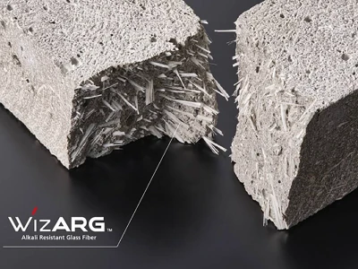
Steel fibre reinforced concrete is defined as a concrete, containing discontinuous discrete steel fibres. Steel fibres are incorporated in concrete to improve its crack resistance, ductility, energy absorption and impact resistance characteristics.
Properly designed and dosed SFRC can reduce or even eliminate cracking a common cause for concern in plain concrete.
The article talks about various aspects of steel fibre reinforced concrete Viz. Design of SFRC floor based on lose berg's yield line model, resistance to corrosion, selection criteria, mix design and other practical considerations as applicable to Shapoorji Palonji project site in Coimbatore.
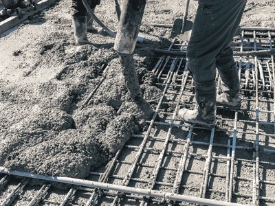
Steel fibre reinforced floor is defined as a floor made of concrete, containing discontinuous discrete steel fibres. Steel fibres are incorporated in floor concrete to improve its crack resistance, ductility, energy absorption and impact resistance characteristics.
Properly designed and dosed SFRC floor can reduce or even eliminate cracking a common cause for concern in plain concrete.
Industrial floors are generally subjected to Loads such as Point load, UDL and Wheel Load. In Interest of explaining load effects certain loads and sub base values are assumed to arrive at Flexural Stress and corresponding dosage. Other assumptions such as temperature, Joint distance, loading factor can be made available on request.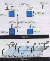
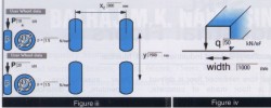 Wheel loads are loads coming from moving equipment like Forklift. The diagram gives details of loads arising out of a 6 ton capacity Forklift having a tire pressure of 1.5 N/mm ^2 (Figure iii).
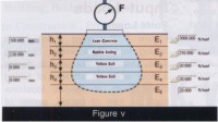 Sub base plays an important role in floor. Generally, subbase (Figure v) is seen in industries. To analyze the effect of subbase on floor design, it is necessary to arrive at equivalent E-modulus or CBR value of the subbase.
If there are more than 2 layer of sub-base defined the equivalent E-modulus of the ground is calculated using the formula below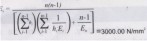
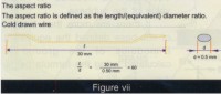
 Higher aspect ratio (Figure vii) always gives better performance of the SFRC with respect to flexural strength, impact resistance, toughness, ductility, crack resistance etc.
Unfortunately, the higher the aspect ratio and volume concentration of the fibre, the more difficult the concrete becomes to mix, convey and pour. Thus there are practical limits to the amount of single fibres, which can be added to SFRC, with the amount varying with the different geometrical characteristics of the several fibre types. Loose steel fibres with a high 1/d aspect ratio, which is essential for good reinforcement, are difficult to add to the concrete and to spread evenly in the mixture.
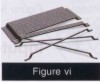
 BEKAERT has glued (Figure viii) the loose fibres together with water-soluble glue into bundles of 30-50 fibres to facilitate handling of the Dramix steel fibres. The individual Dramix steel fibres have the necessary high 1/d aspect ratio, but as they are glued together in compact bundles, they have approximately the same size as the other aggregates. Glued Dramix steel fibres present no difficulty in mixing. They are added as an extra aggregate and require no special equipment to be added to the mix, whether dry mix or wet mix. The hooked ends improve the bond and anchorage of the Dramix steel fibres in the concrete/shotcrete and increase the reinforcing efficiency and ductility. Hooked ends are proved to be best as compared to any other shape of fibres. Bekaert has done extensive research on same copies of which can be made available on request.
The dosage of fibres for a certain performance varies as per type of fibre used. This can be established by making a proper design followed by field test.
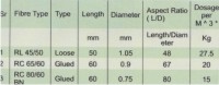
ollowing table gives comparison of various types of fibres in terms of dosage.
* Results valid only for Dramix Fibres
Although unit cost of lower aspect ratio (45) fibre is less, due to high dosage ( 27.5) Kg) per M ^3 cost of SFRC becomes very high as compared to that of SFRC with lower dosage (15 kg) of High Aspect ratio (80) Fibres.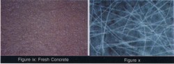 Steel fibre reinforced concrete is better concrete as compared to RCC in certain applications. To make this technology practically possible, it is very much necessary to give importance to fibre geometry, concrete consistency, gradation etc. What we want is concrete with right mix and homogeneous dispersion of steel fibres (Figures iX & X).
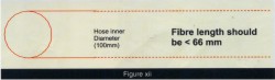
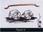 Length of the fibre should be more than sum total two Aggregate sizes (Fig Xi). At the same time fibre length should not exceed 2/3rd of the inner dia of the conveying system (Fig Xii).
Here first factor is related to interlocking of two aggregates whereas second factor is related to workability of concrete through the pumping system.
 In order to have more networking of fibres, it is suggested to have fibres with highest available L/D ratio or least available diameter which finally gives more fibres per kilo ( (Fig Xiii)
Length: 60 MM
Diameter: 0.9 MM
Formation: Glued
Anchorage : Hooked End (Dramix)
Tensile Strength : > 1000 N/MM ^2
Dosage : 30 KG/ M^3
Type 2
Length: 60 MM
Diameter: 0.75 MM
Formation: Glued
Anchorage : Hooked End (Dramix)
Tensile Strength : > 1000 N/MM ^2
Dosage : 20 KG/ M^3
In order to create more paste in existing formulae of concrete following suggestions were made to job site.
Six Samples of various combinations were checked for fibre dispersion as follows.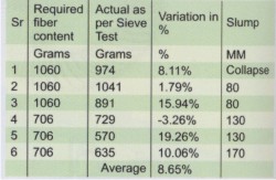
Steel fibres being an essential part of this design should be selected very carefully as discussed in the paper. More emphasis should be given on total cost impact than per unit cost.
Although proper design and economics is important for the project, it is very much necessary to engineer the concrete to suit the selected fibre geometry. Concrete consistency and gradation should be different for every mix and should depend on the type of fibre as suggested by manufacturer.
During the last three decades SFRC was considered a new technology for construction industry. However, this technology has found high acceptance among the construction industry. Currently, steel fibers are used mainly in industrial flooring, tunneling, pavements etc.
Construction time and durability are the main factors among the various advantages which help SFRC to command its superiority over other methods.
In our country, lot has been written or published about SFRC, but we are not using this technology as it is being used in other countries there is a definite and detail approach on how to design fiber concrete and achieve a homogeneous dispersion of steel fibres. Steel fibre geometry and grading of concrete play a vital role in SFRC.
Steel fibre reinforced concrete is defined as a concrete, containing discontinuous discrete steel fibres. Steel fibres are incorporated in concrete to improve its crack resistance, ductility, energy absorption and impact resistance characteristics.
Properly designed and dosed SFRC can reduce or even eliminate cracking a common cause for concern in plain concrete.
The article talks about various aspects of steel fibre reinforced concrete Viz. Design of SFRC floor based on lose berg's yield line model, resistance to corrosion, selection criteria, mix design and other practical considerations as applicable to Shapoorji Palonji project site in Coimbatore.
Steel fibre reinforced floor is defined as a floor made of concrete, containing discontinuous discrete steel fibres. Steel fibres are incorporated in floor concrete to improve its crack resistance, ductility, energy absorption and impact resistance characteristics.
Properly designed and dosed SFRC floor can reduce or even eliminate cracking a common cause for concern in plain concrete.
Scope
Concrete composition, admixtures, placing and curing play another evident role but here focus will be on a sample design of SFRC Industrial floors using Drapro and selection criteria of steel fibre.Industrial floors are generally subjected to Loads such as Point load, UDL and Wheel Load. In Interest of explaining load effects certain loads and sub base values are assumed to arrive at Flexural Stress and corresponding dosage. Other assumptions such as temperature, Joint distance, loading factor can be made available on request.
Input–Loads
Point Loads
(Figure i) illustrates Point loads arising from Rack loads, Stacking Area, Lines etc. We need to design a floor which is efficient of taking these loads at various locations such as joint of panels, center of panels, etc.Anticipated Location of Load
(Figure ii) illustrates various location of loads as discussed in above paragraph.Wheel Loads
UDL
(Figure iv) illustrates UDL of 5 Ton / M ^2.Input- Sub Base
If there are more than 2 layer of sub-base defined the equivalent E-modulus of the ground is calculated using the formula below
Result
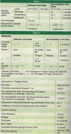
As it is not known beforehand which yield will occur first, we have to consider all possible load combinations. After considering various load combinations and locations maximum moments (Table i) are foreseen.Steel Fibres
Selection Criteria
The most important aspects controlling the performance of steel fibres in concrete are as follows:- Tensile Strength on the wire ( > 1000 Mpa)
- Aspect ratio
- Geometrical shape
Unfortunately, the higher the aspect ratio and volume concentration of the fibre, the more difficult the concrete becomes to mix, convey and pour. Thus there are practical limits to the amount of single fibres, which can be added to SFRC, with the amount varying with the different geometrical characteristics of the several fibre types. Loose steel fibres with a high 1/d aspect ratio, which is essential for good reinforcement, are difficult to add to the concrete and to spread evenly in the mixture.
Fibre Dosage
This is one of the most important elements in SFRC. As discussed earlier fibre performance clearly depends upon parameters like tensile strength, aspect ratio, and anchorage.The dosage of fibres for a certain performance varies as per type of fibre used. This can be established by making a proper design followed by field test.
ollowing table gives comparison of various types of fibres in terms of dosage.
Comparison with Alternatives
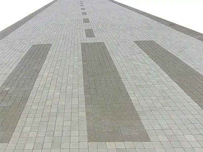
A conventional pavement with 200 mm Thk with single Mesh can be replaced by a 120 mm Thk (SFRC) pavement with following combinations.* Results valid only for Dramix Fibres
Although unit cost of lower aspect ratio (45) fibre is less, due to high dosage ( 27.5) Kg) per M ^3 cost of SFRC becomes very high as compared to that of SFRC with lower dosage (15 kg) of High Aspect ratio (80) Fibres.
Practical Considerations
Fibre Geometry
Here first factor is related to interlocking of two aggregates whereas second factor is related to workability of concrete through the pumping system.
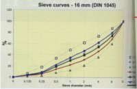
Concrete Consistency and Gradation
In addition to selection of appropriate fibres, it is very much necessary to have consistent concrete with continues gradation. What fibres want is concrete with enough paste around the aggregates.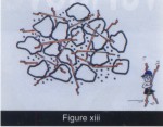 |
 |
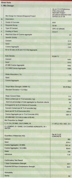
Project at Coimbatore
Given Facts
1. Mix Design
2. Steel Fibres
Type 1Length: 60 MM
Diameter: 0.9 MM
Formation: Glued
Anchorage : Hooked End (Dramix)
Tensile Strength : > 1000 N/MM ^2
Dosage : 30 KG/ M^3
Type 2
Length: 60 MM
Diameter: 0.75 MM
Formation: Glued
Anchorage : Hooked End (Dramix)
Tensile Strength : > 1000 N/MM ^2
Dosage : 20 KG/ M^3
In order to create more paste in existing formulae of concrete following suggestions were made to job site.
- Depending on availability pl. add either of following (30-50 Kg per M ^3, 1. Fine sand <= .125mm, 2. Fly Ash, 3. GGBS)
- Start from W/C Ratio of 0.5 and take trials up to 0.46
- Increase cement content to 380-400 KG ( Trail and error)
- Increase slump to minimum 80 and maximum 120 (Trial and Error)
Six Samples of various combinations were checked for fibre dispersion as follows.
- No balls were observed during the mix.
- W/C Ratio maintained was 0.48/0.49.
- Make fine sand available and reduce cement content
- Reduce water cement ratio to 0.46
- Maintain slump in the range of 80-120
- If possible increase mixer speed to 18 RPM
Conclusion
Steel fibre reinforced Industrial floors can be designed using Lose berg's Yield line model. At www.bekaert.com/building one can register to get a free design of Steel fibre Industrial floors based on the inputs provided.Steel fibres being an essential part of this design should be selected very carefully as discussed in the paper. More emphasis should be given on total cost impact than per unit cost.
Although proper design and economics is important for the project, it is very much necessary to engineer the concrete to suit the selected fibre geometry. Concrete consistency and gradation should be different for every mix and should depend on the type of fibre as suggested by manufacturer.
References
- Gerhard Vitt Design–Presentation at Malenovice approach for Dramix Industrial floors.
- Beckett D, Humphreys J The Thames Polytechnic, Dart ford: Comparative tests on Plain, Fabric Reinforced and Steel Fibre reinforced Concrete Ground Slabs.
- Lose berg A.: Design Methods for structurally Reinforced Concrete Pavements, Sweden, 1961.
- Thooft H: Dramix Steel Fibre Industrial floor Design in accordance with the Concrete Society TR34.
- Practical guide to the installation of Dramix Steel fibre concrete floors.
- Ganesh P. Chaudhari, Design of SFRC Industrial floor Indian Concrete Institute, Seminar on Flooring and Foundations.
- Ganesh P. Chaudhari, Design of Durable SFRC Industrial Floor, International conference of "Sustainable Concrete Construction "ACI, 8-10 February Rantagiri, India.
Published on:
15 September 2009
Published in: NBM&CW Febuary 2009
Share:
We Value Your Comment