Robustness of Self-Compacting Geopolymer Concrete (SCGC)
Warren Mc Kenzie, Technical Manager, BASF Construction Chemicals, Dubai, U.A.E
It’s widely known and has been reported on numerous occasions and in multiple journals that concrete is one of the most used construction materials in the world. With current cement production in excess of 2.8 billion tonnes globally it is forecast to exceed four billion tonnes year on year. [1] The production of OPC contributes to greenhouse gasses, in the form of CO2. Latest reports indicate the 0.6 to 0.8 kg of CO2 is emitted per 1 kg of OPC produced. The net result: CO2 contributes to approximately 65% of global warming. The cement industry is the third largest contributor, responsible for approximately 5 - 6% of CO2. [1][2]
Despite the numerous uses and benefits of concrete OPC remains the primary source of binder in conventional concrete. The production of which consumes vast quantities of energy while simultaneously depleting quarried resources. However, these concerns remain a secondary concern compared to the volume of CO2 produced as a result of the calcination process. Through the implementation of sustainable developments within the civil engineering society, the use of materials with lower environmental impact have gained traction. This has led to the acceptance, use and specification of materials such as PFa, GGBS, MS, etc.
Based on their characteristic properties, pozzolanic and/or hydraulic, these materials are considered to be either secondary or supplementary materials. Replacement of OPC with PFa and GGBS are generally minimal, however research has shown that high levels of replacement are possible. Recently it has been reported that environmentally friendly concrete can be produced by replacing OPC with materials such as PFa and GGBS and activating them using a high alkali solution(s). This process is affectionately referred to/identified as AAM or Geopolymer concrete, a term coined by French Prof. Davidovits. [3][4]
Geopolymer concrete provides a sustainable, environmentally friendly alternative to OPC based concrete by reducing CO2 emission by up to 45% while remaining economically competitive. [1] These reductions are often looked at only as operational CO2 (oCO2) and not as the embodied carbon dioxide (eCO2), which can be defined as the emissions derived from the construction and disposal phase in terms of the element’s life cycle. Geopolymer concrete has been successfully deployed in countries such as Australia. The next progressional step in the evolution of concrete technology is a truly revolutionary material, Self-Compacting Geopolymer Concrete (SCGC). [5][6] SCGS is in a situation similar to what conventional Portland cement based self-compacting concrete (SCC) was, where despite the numerous benefits associated with SCC such as improved durability, improved production rate/output, reduction of repairs reduced or reallocation of labour etc. the sensitivity and robustness of the mix remains questionable and unproven. [7][8][9]
Scope
Most studies on geopolymer concrete have focused on the reaction kinetics of the polymerization process rather than the development and understanding of a concrete that can be introduced into the industry, with a limited number of studies focusing on concrete as opposed to mortar mixes. Review of literature shows that the focus has been on molarity of the activator and the Al/Si ratio with little regard to the complexities of preparing a mix design, one that is robust enough to tolerate variation in water content. The term “robustness” is open to interpretation in the industry as there are various definitions of robustness for concrete. For example, RILEM TC 288 MPS classifies robustness as “the characteristic of a mixture that encompasses its tolerance to variation in constituent characteristics and quantities, variations during concrete mixing, transport, and placement, as well as environmental conditions”. [10] While the European Guidelines defines robustness as “the capacity of concrete to retain its fresh properties when small variations in the property’s quantities of the constituent materials occur”. [11] To investigate the robustness the mixing water was decreased by 5 l/m3 (3.57%) and 10 l/m3 (7.14%) or increase by 5 l/m3 (3.57%) and 10 l/ m3 (7.14%), presenting with a total variation of 20 l/m3 (14.28%).
Fly Ash Based Geopolymer
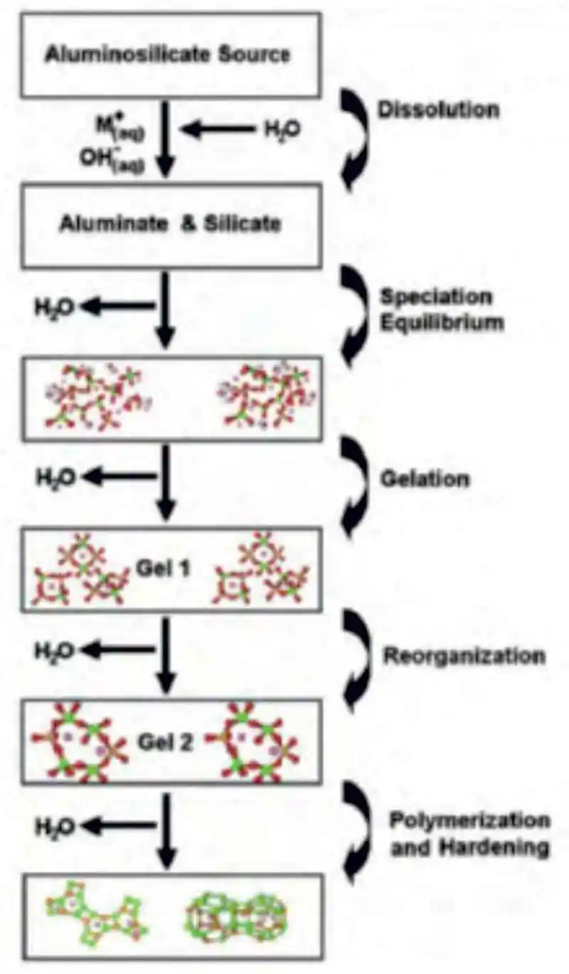 Figure 1: A conceptual model of the polymerization of aluminosilicates using alkaline activation
This process is affectionately referred to/identified as geopolymer concrete or alkali-activated material (AAM). Going forward the term geopolymer will be used as it is preferred by most researchers and the industry. The typical geopolymerization process of Figure 1, [14] provides a very general and linear illustration of the different phases in the polymerization process while Figure 2, illustrates different poly(sialate) structures formed as a result of the different Si:Al ratios. [15] The term poly(sialate) is a chemical designation of geopolymer based on silica-aluminates, where the sialate is the abbreviation for silicon-oxo-aluminate and the alkali may be either sodium (Na+), potassium (K+), lithium (Li+) or calcium (Ca2+). [12] Polysialates range from amorphous to semi-crystalline three-dimensional silica-aluminate structures and are chain and ring polymers with Si4+ and Al3+ in a IV fold coordination with oxygen. The accepted formula of polysiliates is; Mn(-(SiO2)z-AlO2)n.wH2O, where (M) is a cation and (n) is a degree of poly condensation.
To have successful polymerization, the formation of a (Mz(AlO2)x(SiO2)y.nMOH.H2O) gel is critical and a regarded as a dominant step in the geopolymerization process.
Ground-Granulated Blastfurnace Slag Based Geopolymer
Factors effecting the strength development of geopolymer with GGBS as the primary source of binder are: the type and dosage of alkaline activator, the means of adding said activator, the type and fineness of binder, ratio of SiO2:Na2O, curing temperatures and water:binder ratio. [16] The reaction of GGBS based geopolymer is different from that of PFa. The latent hydraulic GGBS main component is the development of calcium silicate hydrate (C-S-H) gel along with aluminium resulting in calcium silicate hydrate with aluminium gel (C-A-S-H), similar to the C-S-H formed by OPC based concretes. [17] The C-A-S-H formed through alkali activation has a Ca:Si ratio below 1.5 whereas the Ca:Si ratio of OPC based concrete is approximately 2.0. [12][18][19]
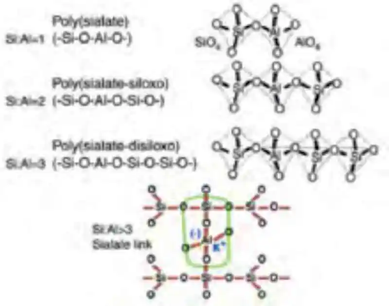 Figure 2: Poly(sialates) structures of geopolymer as per Davidovits
The hydration process is effected by the sodium content and the Ca:Si ratio and begins with the destruction of the slag bonds Ca-O, Mg-O, Si-O-Si, Al-O-A and Al-O-Si before a Si-Al layer is formed of the binder prior to the formation of the hydration products as per Figure 3.
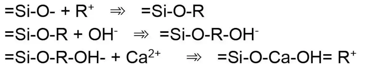 Figure 3: A series of reactions in the activation process of GGBS
The nature and composition of products formed during the activation of GGBS remain controversial and require continuous research. Most research conclude and accept the following assertions: [18]
- The main hydration product is a composition of calcium silicate hydrate with aluminium (C-A-S-H gel) with a Ca:Si ratio less than 1.5;
- The structure and composition of the C-A-S-H gel is dependent on the type and amount of activator used.
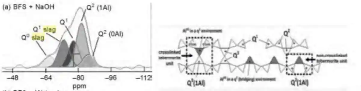 Figure 4: C-A-S-H formation based on NaOH
Sodium Hydroxide
NaOH more commonly known as caustic soda or lye is produced via electrolysis. Three types of electrolytic cells are used, Castner-Kellner cells (Mercury process), Nelson diaphragm cells and membrane cells. The preferred method is shown in Figure 2.30 and discussed further below. [21] The membrane cell method is favoured for the production of NaOH; it has a low energy demand to produce pure NaOH with no hazardous waste. The cell consists of a two-compartment system with a titanium anode, nickel cathode and an ion-exchange membrane separating the anode from the cathode. Saturated brine solution enters the anode compartment where oxidation takes places releasing chlorine gas, 2Cl-(aq) => Cl2(g) + 2e-. The depleted brine is removed and replaced in a continuous process. [21]
The membrane selectively allows Na+ and water to migrate from the anode compartment to the cathode compartment where the solution reacting with the cathode releases hydrogen, 2H2O(i) + 2e => H2(g) + 2OH-(aq).
The Na+ combines with the OH- to form a concentrated NaOH, 2H2O(i) + 2Cl-(aq) + 2Na+(aq) => 2Na+(aq) + 2OH-(aq) + H2(g) + Cl2(g). Solid NaOH is obtained by the evaporation of this solution.[68]
Molarity
The concentration of the solution is referred to as molarity and is defined as the number of moles of solute per liter of solution. The molarity of NaOH is calculated where molarity is compared to moles in solute. The relationship between activator molarity and the performance (compressive strength) of geopolymer concrete has been studied. Geopolymer produced using a molarity of 14 showed significant increase in compressive strength while mixes produced with 18 mole showed marginal decrease in compressive strength. It has been observed that increasing the molarity of the activator leads to better results. [22][23][24]
Several reports have been made regarding the dosage of activator; however, they remain inconsistent. For example, geopolymer prepared with NaOH within the range of 1-10% by mass of binder reported that the higher the dosage, the better the strength; other reports indicate the variation of dosage within the range of 3-11% had little effect on the strength. [25]
Wang reports that to increase the molarity in combination with the dosage of activator, defined as the ratio between Na2O in the activator and binder as a percentage, has a significant influence on the compressive strength. [25][26]
It’s reported that the optimum Na2O dosage for GGBS based geopolymer is between 3-6%, based on early strength requirements and the type of GGBS used. However, the Na2O value varies according to total binder volumes as illustrated in Table 2.9 whereby the activator dosage remains constant at 25l/m3 and the total binder ranges from 300 kg/m3 to 500 kg/m3.
Molarity in the case of NaOH is limited to a maximum of approximately 19 mole per litre as NaOH solidifies at 20°C at a concentration of 52% by mass. [85] Therefore a solution of approximately 18 mole (M) NaOH was prepared by dissolving NaOH flakes in water to achieve an approximate 50% mass fraction (w/w). Several trials were conducted using various levels of NaOH before settling on a value as per the proposed mix design. Laboratory trials indicated a strong correlation to results found in research, showing that there appears to be an optimum dosage for the activator.
Literature has revealed that increasing the molarity of activators has a negative effect on plastic properties such as slump-flow, v-funnel and slump-flow t-500 times; yet a positive effect on compressive strength. [6][27][28][29][30][31][12][13]
With the primary focus being on the molarity of the activator(s), the effect of free water has been erroneously disregarded. Numbers, in the first row of Table 1, taken from [29] illustrate the focus on molarity; not taking into account the change of free water as the dosage of activator remains consistent, depicted in the rows that follow. Table 1 provides a breakdown of total water by calculating the solid content of NaOH at various molarities from a theoretical mix while Figure 5 illustrates the effect of free water on compressive strength.
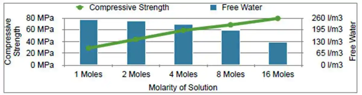 Figure 5: The effect of free water on compressive strength
| Table 1, Breakdown of total water by calculating NaOH solid content at various molarities from a theoretical mix design | ||||||||
| Binder | Coarse Aggregate | Fine Aggregate | Molarity | NaOH Activator | Active NaOH (kg/m3) | Free Water (kg/m3) | Water (12% of Binder) | Total Water in Mix (kg/m3) |
| 425 | 935 | 830 | 210 | 51 | ||||
| 1 | 6.4 | 201.6 | 252.6 | |||||
| 2 | 16.8 | 193.2 | 244.2 | |||||
| 4 | 33.6 | 176.4 | 227.4 | |||||
| 8 | 67.2 | 142.8 | 193.8 | |||||
| 16 | 134.4 | 75.6 | 126.6 | |||||
Super Plasticizers
Commercial superplasticizers such as lignosulphonate, sulphonate naphthalene formaldehyde, sulphonate melamine formaldehyde and polycarboxylate ether, used in OPC based concretes, have been well documented in literature. The use of these constituents has become common practice as they adhere onto the cement surface, often building up multiple layers on individual grains, whereby they deflocculate and disperse the agglomerated cement particles through the following mechanisms: electrostatic repulsion, reduction of the surface tension of water and steric hinderance, releasing the entrapped water and increasing fluidification. [32][33]
The charge of both cement and superplasticizers is recorded as zeta potentials, which is the function of the charge of the particles with absorbed polymers. Therefore, it should be noted that OPC is positively charged to approximately +10 mV as a result of the multi-phase dissolution of the silanol phases. Superplasticizers, with a negative zeta potential, endeavour to reduce the positive zeta potential in the system. By cancelling one another out, the superplasticizers become absorbed onto the cement grain. Despite the latest generation superplasticizers having a zeta potential of -5 to -10 mV they are rendered useless in the high alkaline environment of geopolymer and provide little to no improvement in workability; however, they may compromise the set time and compressive strength by as much as 50%. [34][35]
Conventional PCE’s consist of an anionic backbone which attracts counter ions resulting in the neutralization of their anionic charge and therefore influencing their adsorption characteristics. The presence of cations and the amount found within the pore solution blocks the negative charges resulting in a reduction of adsorption onto the binder and therefore provides minimal plasticizing properties. [15]
BASF Construction Chemicals have developed a superplasticizing admixture for use in geopolymer concrete. However, the intellectual property of the admixture is protected by patents and other commercialization processes therefore the properties of the admixture will not be discussed or disclosed.
Mix Design
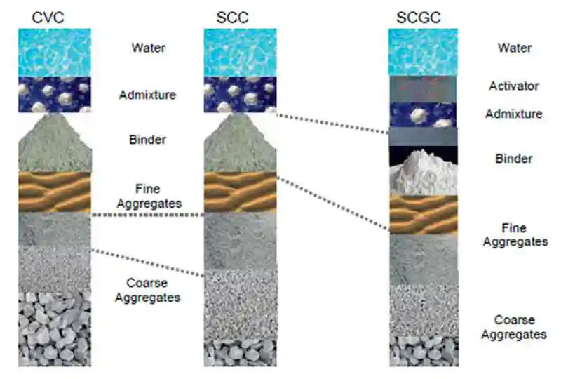 Figure 6: Progression of mix proportioning between CVC, SCC and SCGC
Both SCC and SCGC require a higher paste content compared CVC and is achieved by the manipulation of the aggregate proportions, binder content and total water content. Figure 6 shows the progression of mix proportions form CVC to SCC to SCGC. Reducing the ratio of coarse aggregate to fine aggregate adds stability to the mix, although it may be necessary to substitute the largest aggregate for one size down; i.e., 20 mm to 10 mm.
A well-designed thixotropic SCC/SCGC should be able to resist dynamic segregation in the fluid state yet reduce the lateral stress on the formwork i.e. hydrostatic pressure. Once the concrete comes to a rest, the fluid structure can restore the yield stress and prevents further dynamic, segregation a phenomenon resulting from flocculation. [36][37]
Based on PPP and the conceptual models shown, a theoretical mix design, Table 2, has been developed to meet the guidelines, as set out by BS EN 206:2013 and EFNARC. [38][39]
| Table 2, Theoretically proposed mix design | ||||||
| Raw Material | Kg/m3 | % m3 | eCO2 | Dry vs Liquid % | Aggregate vs Mix % | Coarse vs Fine vs Liquid % |
| 20mm Stone | 380 | 11.76 | 3.53 | 91.60 | 73.95 | 29.62 |
| 10mm Stone | 425 | 7.85 | ||||
| Crusher Sand | 680 | 28.57 | 3.78 | 61.97 | ||
| Dune Sand | 375 | 15.76 | ||||
| GGBS | 375 | 15.76 | 19.50 | 26.05 | ||
| MS | 45 | 1.89 | 0.63 | |||
| Water | 140 | 5.88 | 0.14 | 8.40 | 8.40 | |
| Admixture | 35 | 1.47 | 0.35 | |||
| NaOH | 25 | 1.05 | 28.75 | |||
| Theoretical Total | 2 380 | 100.00 | 0.024 | 100.00 | 100.00 | 100.00 |
Curing
It is thought that geopolymer concrete produced utilizing conventional and well-established curing procedures will add further confirmation regarding the robustness of the mix.
Curing of conventional concrete has been described as “the maintenance of appropriate moisture and temperature conditions to permit the continuation of the hydration or pozzolanic reaction”. The “hydration” phase of geopolymer concrete is more of a polymerization phase than an actual hydration phase as is the case in conventional concrete where CSH is formed. It is thought that geopolymer concrete produced with a basic GGBS will have a minimal calcium content and could be considered as self-curing, where no water curing is required.
Evaluation of Plastic Properties
In an effort to ensure a harmonious and representative evaluation of each test characteristic, concrete used for a single test is returned to the pan where it was manually mixed by hand prior to moving onto the next test method, i.e. following the completion of the mixing sequence the slump-flow and slump-flow t500 were recorded. The concrete was then returned to the pan and using a scoop, the concrete was mixed by hand to form a representative sample before conducting the J-ring test. The procedure followed for evaluation of the plastic properties was based on the ergonomics of the laboratory and were: slump flow and slump-flow t500, J-ring, V-funnel, plastic viscosity and finally sieve segregation. After which all concrete was returned to the mixer and covered with polythene to measure slump retention
Slump Flow
The slump-flow values of the various mixes highlight the direct effect water has on workability. The slump-flow decreases in a near linear trajectory as the mixing water is reduced; while slump-flow increases, as water content increases, in a more parabolic trajectory, indicating that further increases in water content would cause segregation and thus reduce the slump-flow values as depicted in Figure 7 and Figure 8. As per BS EN 206:2013 the concrete is classed as SF3.
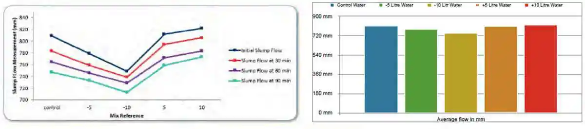 Figure 7: Slump-flow line chart summary of the effect various water contents have at T= 0, T= 30, T= 60, and T=90 minutes
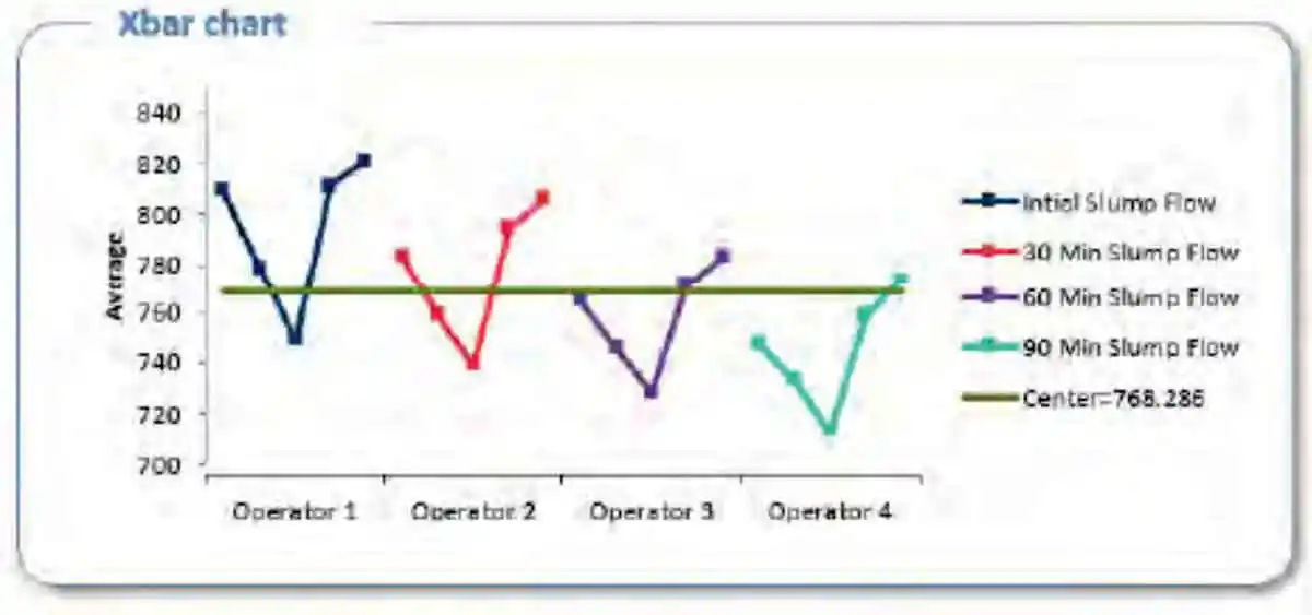 Figure 8: Xbar chart summary of the effect various water contents have at T= 0, T= 30, T= 60, and T=90 minutes on slump-flow
Plastic Viscosity
The results recorded from the plastic viscosity measurement are reported as Pa.S in Table 3. Analysing the box plot Figure 9, the histogram Figure 10, it is noted the that the plastic viscosity increases as the water content decreases and visa versa as the plastic viscosity decreases as the total water content is increased as per figure 11. These results follow the notion that variation in water has a direct effect on plastic viscosity as a result of the relationship between stress and rate of strain.
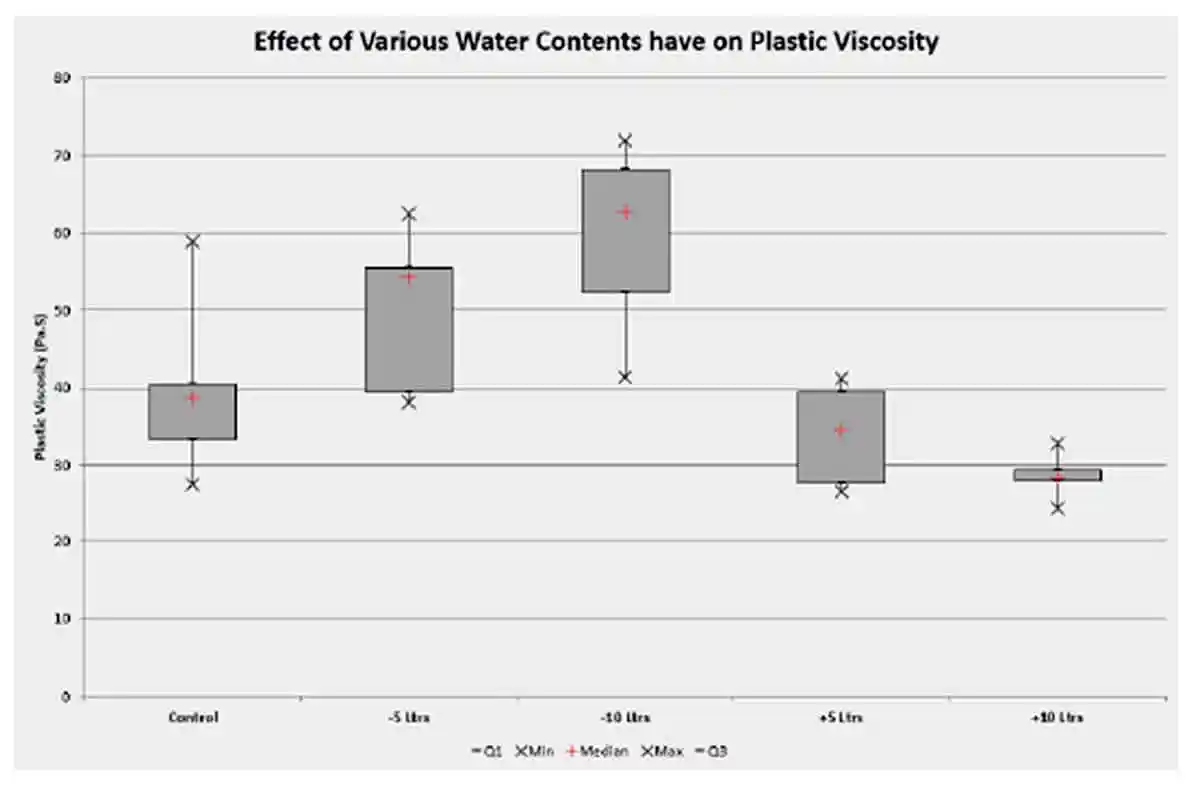 Figure 9: Plastic viscosity box plot reference mix with water contents decreased and increased by 5 and 10 litres respectively
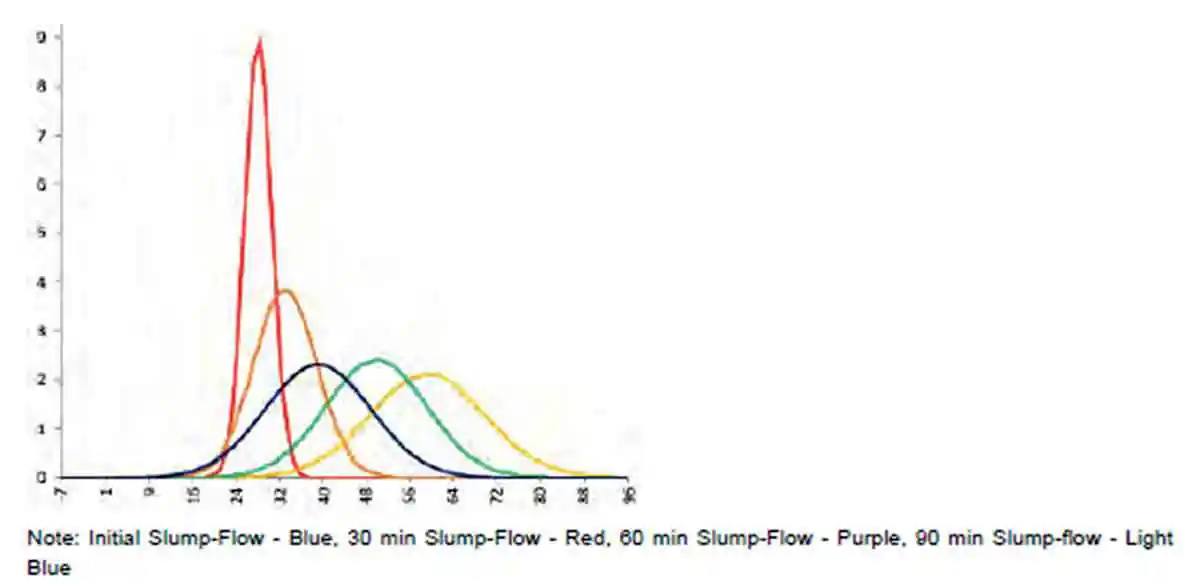 Figure 10: Plastic viscosity histogram reference mix with water contents decreased and increased by 5 and 10 litres respectively
| Table 3, Plastic viscosity values (Pa.S) reference mix with water contents decreased and increased by 5 and 10 litres respectively | |||||
| Plastic Viscosity | Reference Mix | -5 Ltr Water Mix | -10 Ltr Water Mix | +5 Ltr Water Mix | +10 Ltr Water Mix |
| Repeat 1 | 38.9 | 55.5 | 54.8 | 26.7 | 24.4 |
| Repeat 2 | 38.4 | 54.2 | 63.7 | 39.5 | 29.5 |
| Repeat 3 | 58.8 | 39.5 | 52.3 | 27.7 | 28.6 |
| Repeat 4 | 38.5 | 38.1 | 41.4 | 29.0 | 28.5 |
| Repeat 5 | 40.4 | 45.0 | 62.7 | 41.2 | 32.8 |
| Repeat 6 | 33.3 | 62.6 | 71.9 | 35.1 | 28.1 |
| Repeat 7 | 27.5 | 55.2 | 68.2 | 34.6 | 28.0 |
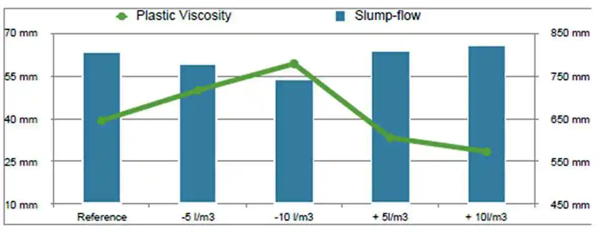 Figure 11: Plastic viscosity values compared to average slump-flow values for reference mix with water contents decreased and increased by 5 and 10 litres respectively
Compressive Strength
The strength development of test specimens remain consistent despite being subjected to different curing methods. The strength development between mixes is shown in Figure 12, providing a clear illustration of the strength development trend. Figures 1, 2, 3, 4, 5 in Appendix 3 provide a direct comparison between water cured and air cured specimens per mix design. These results are also shown in Tables 1, 2, 3, 4, 5, 6, 7, 8, 9 and 10 in Appendix 3. Specimens cured in the stability chamber demonstrated that the water curing was not a requirement to ensure the geopolymerization process continues. Furthermore, the continuous strength development indicates that this process had not concluded and that higher strengths could be expected at later ages.
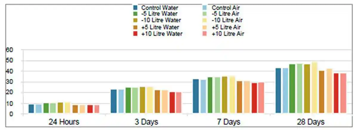 Figure 12: Strength development of water cured vs air cured
The influence of the water content on the compressive strength suggests the water:binder ratio is a critical factor in the production of geopolymer concrete. Following extensive research into activation of geopolymer concrete, molarity can be regarded as a critical factor regarding the success of the mix. It has also been noted that molarity is only ever considered as a value of the activator and not of the total mix design. It is therefore proposed that the active molarity of activator and subsequently the active Na2O be used for a more accurate calculation in the development of geopolymer concrete. In other words, a mix design using 250 l/ m3 water and 50 l/ m3 of 18 M sodium hydroxide has an active / effective molarity of 0.126 in a m3. Using a superplasticizer to reduce the water content by 100 litres increases the active/effective molarity to 0.189 in a m3, an improvement of more than 65%.
Summary
The results of the investigation into both plastic and hardened properties, as well as curing, can be summarized as follows:
- Geopolymer produced using GGBS blended with MS presents with acceptable performance properties and therefore validates the replacement of 100% OPC.
- The use of exciting test methods were used in accordance with the appropriate method except where highlighted and discussed.
- Changes in water content had a direct effect on the plastic properties. However, evidence suggests that the changes in plastic properties were subtle, proving the concrete was able to tolerate the variance without segregation.
- The decrease in water content had the greatest effect on the pass-ability of the v-funnel and the plastic viscosity.
- The strength development of the various mixes was not affected by the curing procedures/methodologies. However, the compressive strength is related to the water content of the mix and not the Na2O as previously reported.
- While the methods of curing had minimal effect on compressive strength, the specimens subjected to air curing presented with improved performance properties with regard to RCPT and water absorption. The low water absorption can be attributed to a dense matrix as a result of the fineness of the GGBS and thus compliments the chloride resistance properties of geopolymer producing a longer service life.
- The porosity of the concrete represented by the low water absorption values are attributed to the high fineness and irregular shape of the GGBS. Both the high fineness and irregular shape increase the surface area and therefore increased the reaction between the binder and activator.
- The improved chloride diffusion rate results from the low porosity of the concrete. However, it is noted that the concentration of NaOH increases the chloride binding capacity of the concrete thereby providing a dual action system for the reduction of chloride ingress.
-
While all initial results indicate geopolymer produced with GGBS and MS provide acceptable compressive strength and improved durability results, the long-term performance properties require further examination in order to be validated.
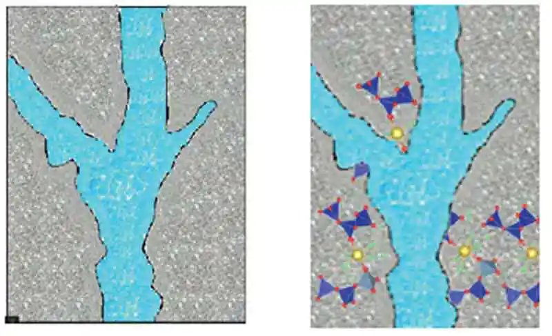 Figure 13: The saturated capillaries result in polymerization around the capillaries
 - It is theorized that the compromised performance properties of hardened properties subjected to water curing is a result of excess water interfering with the polymerization process as illustrated in Figure 13, with saturated capillaries forcing the polymerization to wrap around the capillary; while Figure 14 illustrates how the C-A-S-H gel may cross through the capillary thereby changing and limiting the absorption properties.
- Although this interference is negligible for compressive strength, it is thought that in the absence of excess water, the C-A-S-H gel is allowed to form through the capillaries thereby providing a denser matrix and improving the overall durability of the concrete.
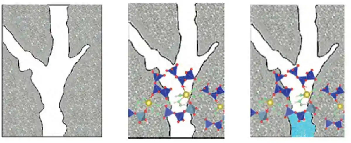 Figure 14: C-A-S-H gel polymerizes through the empty capillaries
Conclusion
This chapter presents the main conclusions which can be drawn following the investigation into the robustness of SCGC to changes in water content and the effect curing has on the hardened properties of the various mixes.
Analysis of the results from this study present the following conclusions:
- The results confirm SCGC is robust enough to tolerate changes in water content without segregation, contrary to its reputation of being sensitive to change in moisture.
- The study found that SCGC is repeatable across a range of tests, in both the plastic and hardened states.
- Changes in plastic properties remain intuitive, whereby the increase or decrease of water has the desired/expected result.
- The results derived from air curing are counter intuitive and produced improved durability results. This finding introduces the industry to a unique advantage over conventional concrete, with further cost saving possibility as a result of/in a reduction of curing cost.
- SCGC may be regarded as state of the art in the continuous progression to improve concrete quality and extend service life of structures. However, there remains much work needed till we achieve an understanding similar to that of conventional concrete.
- The primary hydration product is amorphous and comprised of C-A-S-H gel.
- All mix designs remained within the limits set out by EN BS 206:2013, despite some variation from one classification to another.
- The mix design proportions and understanding of how they interact in a holistic manner is a primary step to ensure a robust mix design is produced.
- The strength development of geopolymer is a complex multi-stage process, which is affected by several components such as water:binder ratio, Si:Al ratios, activator types and dosage, the percentage of Na2O per binder, as well as, the total free molarity.
- Despite changes to the curing methodology geopolymer demonstrates suitable performance characteristics for harsh conditions, such as marine environments where there is a need to resist the ingress of chlorides.
- In general, both plastic and hardened properties have successfully demonstrated acceptable performance in the short term. The evaluation of these properties needs to be evaluated to understand the long-term characteristics, insuring there is no relapse of performance at a later stage.
- The use of standard/common test methods proved suitable for the evaluation of the selected properties, however there is a requirement to standardize test procedures for geopolymer concrete, particularly if the specimens are air cured; i.e. drying shrinkage, the specimens may have a higher shrinkage rate initially, however as the capillaries are filled as a result of polymerization the shrinkage value may be lower than that of a water cured specimen.
- Gunaseera, C. Setunge, S and Law, D.W. 2018. Creep and drying shrinkage of different fly-ash-based geopolymers. ACI Materials Journal V116 No.1 pp. 39-49
- Rangan V B. 2014. Geopolymer concrete for environmental protection. The Indian Concrete Journal, Vol. 88, Issue 4, pp. 41-59
- Davidovits J. 1982, The Need To Create A New Technical Langue For The Transfer Of Basic Scientific Information, Published In Transfer And Exploration Of Scientific and Technical Information, Commission Of The Wuropoean Communities, Luxembourg, 1982, pp, 316-320
- Islam. A, Alngaram. U. J, Jumaat. M. Z and Bashar. I. I. 2014, The Development Of Compressive Strength Of Ground Granulated Blast Furnace Slag-Palm Oil Fuel Ash-Fly Based Geopolymer Mortar. Materials And Design, 56. Pp 833-841.
- Geopolymer Concrete, Z16 recommended practice. 2011. Available from: https://www.concreteinstitute.com.au/OnlineStore/Recommended-Practices/Geopolymer-Concrete
- Henigal A.M, Sherif M.A and Hassa N.N, 2017, Study On Properties Of Self-Compacting Geopolymer Concrete. Journal Of Mechanical And Civil Engineering, Volume 14, Issue 2, pp. 52-66.
- Roberts J, 2012. Sensitivity That Self-Compacting Concrete Shows Towards Repeatability In Rocla’s Precast Environment. Cape Peninsula University Of Technology
- Ghoddousi P. and Salehi, A, M. 2017, The Robustness Of Self-Consolidating Concrete Due To Changes In Mixing Water. PeriodicaPolytechnica Civil Engineering, 61(2), pp. 216 - 225
- Krishnamoorthy K. Some Major Issues Of Self-Compacting Concrete, Annamalai University, India. [Accessed 05 January 2019] Available from: https://www.icevirtuallibrary.com/doi/pdf/ 10.1680/rocisd.32477.0047
- De Schutter. G and Khayat. K. H, STAR 228-MPS, Mechanical Properties Of Self- Compacting Concrete. [accessed 16 February 2019] Available Online from: copyhttp://www.springer.com/engineering/civil+engineering/book/978-3-319-03244-3
- BS EN 206:2013, Concrete - Specification, Performance, Production And Conformity.
- Warhono, A. 2015, The durability of Fly Ash Geopolymer and Alkali-Activated Slag Concrete, School of Civil Environmental and Chemical Engineering, RMIT, pp. 1-222
- Van Mele H.R, BiesemansM, Wu J,W,X. 1996. Low-Temperature Synthesized Aluminosilicate Glasses, Journal Of Material Science, 31, pp. 71-79
- Duxson P, Fernandez-Jimenez, Provis. J.L, Lukey G.C, Palomo A, Van Deventer J,S. J. 2007, Geopolymer Technology: The Current State Of The Art. Journal Of Material Science, 42 pp. 2917-2933.
- Li C, Sun H, Li L. 2010. A Review: The Comparison Between Alkali-Activated Slag (Si+Ca) And Metakaolin (Si+Al) Cements. Cement And Concrete Research 40, pp. 1341-1349.
- Rovnaanik, P. 2010. Effect Of Curing Temperature On The Development Of Hard Structure Of Metakaolin-Based Geopolymer. Construction And Building Materials. 24, pp.1176 - 1183.
- Suresh, D and Nagaaju, K, 2105, Ground Granulated Blast Slag (GGBS) in Concrete - A Review. Journal of Mechanical and cCivil Engineering, Volume 12 Issue 4, pp. 76-82
- Garcia-Lodeiro.I, Palomo.A and Fernandez-Jimenez. A, An Overview of the Chemistry of Alkali-Activated Cement Based Binders. In: Handbook of Alkali-activated Cements, Mortars and Concretes. Woodhead Publishing Series in Civil and Structural Engineering:Number 54, pp. 33-40
- Beushausen H. 2009 Self-compacting Concrete. In: Owens, J. Edition 9. Fulton’s Concrete Technology. Midrand, South Africa: Cement And Concrete Institute, pp. 317-327
- Taylor. H.F.W. 1997, Cement Chemistry 2nd Edition. Chapter 7 pp. 187-225
- Sodium Hydroxide and Chlorine production by Electrolysis, [Accessed 08 July 2019] Available Online from: https://www.ausetute.com.au/chloralkali.html
- Abdullah. M. M. A, Kamarudin. H, Mohmmd. H, Hhairul Nizar. I, Rafza. A.R and Zarina.Y. 2011, The relationship of NaOH Molarity, Na2SiO3/NaOH Ratio, Fly Ash/Alkaline Activator Ratio and Curing Temperature to the Strength of Fly Ash-Based Geopolymer. Advanced Materials Research Vols. 328-330 pp. 1475-1482.
- Kabir. S.M.A, Alengaram. J.U, Jumaat. M.Z, Sharmin.A and Islam. Azizul, 2015, Influence of Molarity and Chemical Composition on the Development of Compressive Strength in POFA Based Geopolymer Mortar. Advances in Materials Science and Engineering, Volume 2015 Article ID 647071.
- Madheswan.C.K, Gnanasundar.G and Gopalakrishnan.N, 2013. Effect of Molarity in Geopolymer Concrete. International Journal of Civil and Structural Engineering Volume 4, No.2. pp. 106-115
- Wang. S, Scrivener. K.L and Pratt.P.L. 1993. Factors Affecting the Strength of Alkali-Activated Slag. Cement and Concrete Research. Vol. 24, No.6. pp. 1033-1043.
- Adam. A.A, 2009. Strength And Durability Properties Of Alkali-Activated Slag And Fly Ash- Based Geopolymer Concrete. School of Civil, Environmental And Chemical Engineering RMIT University, Melbourne. pp.25
- Taylor. H.F.W. 1997, Cement Chemistry 2nd Edition. Chapter 9 pp. 261-293
- Adam. A.A, 2009. Strength And Durability Properties Of Alkali-Activated Slag And Fly Ash-Based Geopolymer Concrete. School of Civil, Environmental And Chemical Engineering RMIT University, Melbourne. pp.4
- BS EN 450-1:2005+A1:2007, Fly Ash for Concrete - Part 1: Definition, specifications and Conformity Criteria.
- Jackson, P.J, Portland cement: Classification and Manufacture. In: Lea’s Chemistry of cement and concrete 4th edition, pp. 26
- Northwestern University, the science of concrete. [accessed 15 June 2019] Available on line from: http://iti.northwestern.edu/cement/monograph/monograph5_1.html
- Ramachandran V.S., Malhotra V.M, Jolicoer C. &Spiratos N.1998. Superplasticizers: Properties and applications in concrete pp. 59
- Zingg. A, Winnefeld. F, Holzer. L, Pakusch. J, Becker. S and Gaukelr. L. 2008. Adsorption of polyelectrolytes and its influence of rheology, zeta potential and microstructure of various cement and hydrate phases, Journal of Colloid and Interface Science 323 pp. 301 - 312
- Kong, D, L, K. and Sanjayan, J, G. 2010. Effect Of Elevated Temperatures On Geopolymer Paste, Mortar and Concrete. Cement And Concrete Research. 40, pp. 334-339.
- Edmeads.R.M and Hewlett. P.C, Cement Admixtures. In: Lea’s Chemistry of cement and concrete 4th edition, pp. 853
- Trgger. N, Gregori. A, Ferrara. L and Shah. S. 2012. Correlating Dynamic Segregation of Self-Consolidating Concrete to the Slump-Flow Test, Construction and Building Materials, 28, pp. 499 – 505
- Ovarlez G and Roussel. N. 2006. A Physical Model for the Prediction of Lateral Stress Exerted by Self-Compacting Concrete on Formwork. Materials and Structures, Volume 39, pp. 269 - 279
- BS EN 206:2013, Concrete - Specification, Performance, Production And Conformity.
- EFNARC, The European Guidelines For Self-Compacting Concrete, 2005, www.efnarc.org
Warren Mc Kenzie is a Concrete Technologist and R&D specialist with 10 years’ experience in the industry. He graduated from the University of Leeds, UK, with MSc in civil engineering – specializing in advanced concrete technology. He has focused on topics such as 3D printing and Geopolymer concrete, becoming internationally recognized for his work on the later. He is currently the Technical Manager for BASF Construction Chemical for the Gulf States.
Published on:
15 May 2020
Published in: NBM&CW May 2020
Share:
We Value Your Comment