
Slipform Techniques for Accelerated Construction
Dr. Sudhir Singh Bhaduaria, Prof. & Head; Tarun Kumar Divakar, Lecturer, and Suresh Singh Kushwah, Reader Deptt. of Civil Engineering, University Institute of Technology, Rajiv Gandhi Technological University, Bhopal, Sanjay Chadha, Madhav Institute of Technology and Science, Gwalior
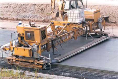
Slipforming is a construction technique which has been used for decades for production of concrete structures. Wide range of structures are slipformed, typically, vertical structures such as towers, bridge columns and offshore platforms and horizontal structures like rigid reinforced concrete pavement, canal lining etc. Apart from vertical structures with uniform thickness, slipforming technique is also used where geometry of structure and wall thickness changes. Slipforming is a continuous working operation (24 hours a day), which requires planned supply of materials, management and supervision. Problems that occur during this process need to be solved instantly. Slipforming involves complex operations as compared to other construction techniques.
Slipforming Technique is defined and described in various ways in literatures. According to Risser (1995) “Slipforming differs from conventional concrete forming because of the forming panels move semi continuously in relation to the concrete surface being formed and form ties are not used.” In the opinion of Camellerie (1978) “Slipforming has proved invaluable tools of construction by cutting cost and man hours and at the same time permitting construction to proceed with maximum safety.” American Concrete Pavement Association (ACPA, 1995) defined, “Slipform paving as a process used to consolidate, form into geometric shape and surface finish a Plain Concrete Cement (PCC) mass by pulling the forms continuously through and surrounding the plastic concrete mass.”
Two types of work are mainly carried out by slipform techniques, namely, Vertical Slipforming and Slipform Paving.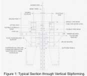 A slipform consists of a framework of horizontal walings and vertical yokes. The slipform panels are connected to each other on inside of the walings. Each side of slipform is connected to vertical yokes that keep panels in position. The jacks for lifting of form are installed on horizontal crossbeam between yokes. When slipform is lifted, all the jacks are activated simultaneously. Hydraulic driven jack is most commonly used. The slipform panel is normally between 1.1 and 1.3 meters high and made up of steel plates.
Principles of vertical slipforming are illustrated in Figure 1. The slipform panels normally have an inclination in vertical plane in order to make panel self-clearing in relation to concrete wall. The inclination depends on stiffness of the slipform panel and concrete pressure. The slipform panel has variable stiffness depending on position and dimension of each yokes and walings. Slipform operation is a continuous working process where the slipform is kept close to full of concrete while it is lifted stepwise. The concrete is placed in 100 to 250 mm thick layers whenever the freeboard height is sufficient. The slipform rate is adjusted so that initial set in concrete occur between 200 to 400 mm above bottom of the panel. Depending on inclination of panel, concrete detach the slipform panel above the hardening front where concrete skeleton is rigid enough to resist back sliding. The slipform rate is planned based on complexity of concrete structure, skills of the work force and available inventory of materials. The setting time of concrete is adjusted to fit planned slipform rate. The setting time of concrete depends on the temperature, concrete composition, and properties of the cement. Concrete setting time is adjusted by using admixtures like retarder or accelerator. Relation between concrete setting time and slipform rate is calculated by using the following equation (Foss, Kjell Tares, 2001).
VS = (h1- h2) / (ts - tt)
Where
VS = Slipform rate [mm / h]
h1 = The distance from the top of the slipform panel to the average curing front [mm]
h2 = The distance from top of the slipform panel to the average freeboard [mm]
ts = Setting time [h]
tt = Time from mixing of the concrete to placing [ h ]
Slipform temperature and transfer of heat from lower concrete layer are taken into consideration when calculating setting time for concrete. The lifting of the panel is carried out at regular intervals depending on the slipform rate. The lifting height is adjusted from 10 to 25 mm depending on desired frequency of lifting. With a hydraulic system, lifting operation is carried out by increasing oil pressure. When oil pressure is sufficient to overcome friction and weight of the form, slipform starts to lift. After slipform is lifted, the form is let down until brakes of the jacks are activated, normally 2 mm downwards.
Walkway Bracket (Inside and Outside) Inside and outside brackets are connected with the respective yoke legs with the help of a pin for easy erection and dismantling along with a pipe strut to support cantilever portion to facilitate placing of concrete, placing of reinforcement, vibration, fixing inserts, block outs, pockets, etc.
Shutters and Walers The function of shutters and waler assemblies is to maintain correct profile of structure to be slip formed and resist concreting pressure.
Lifting Jacks Lifting jacks facilitate lifting of Slipform assembly. Jacks are to be suitably located preferably at equal intervals to enable to lift slipform as one integral unit. Capacity of jacks is decided depending upon the reactions at point of lifting.
Jacking/Climbing Rods Jacking rods are normally located centrally in the wall to be cast or at equal distance in yoke beams depending upon the number of jacks. The jacking rods are generally of 48mm, 32mm, or 25mm in diameter based upon the capacity of jacks. The lifting jack climbs over the jack rod. The entire load of the Slipform assembly is transferred to jacking rods when jacks are energized.
Hydraulic Pump Hydraulic pumps are provided to circulate required quantity of hydraulic oil at desired pressure for energizing jacks to lift the assembly and facilitate its uniform lifting.
Tapered Sleeve Tapered sleeve tubes are provided to prevent fresh concrete coming in contact with jack rods, thus, facilitates extraction of jack rods later. Taper sleeves are attached to yoke beam and move along with slipform and create a hole in concrete around jack rod.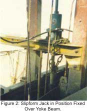 Yoke Beams Yoke is main connecting member between inside and outside yoke legs. Two yoke beams are connected at bottom portion of yoke legs and a single yoke beam is connected at top portion. Jacks are mounted over yoke beams. Yoke beam transfers lifting forces of jacks to yoke legs. A slipform jack fixed in position over yoke beam is illustrated in Figure 2.
Waler Shoe Two waler shoes are provided on each of inside and outside yoke legs. Waler shoes are connected to yoke legs and waler pipes with the help of full threaded bolts. The functions of waler shoe are to adjust inclination of the shutter, adjusting the inclination of yokes and transfer reactions from waler pipes to yoke legs.
Central Ring and Tie Rod Assembly Central ring and tie rod assembly is provided to retain shape of structure to be slipformed. Central ring and flying tie rod assembly moves along with slipform.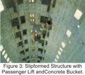 Adjustments are made for inclination of wall, radius and wall thickness if structure under construction has tapered cross section. For inclination of wall, the yoke legs are positioned in such a way that thickness of wall at top and bottom varies. Generally, by providing about 2 mm less to shutter arrangement at top and 2 mm more at bottom, shutter inclination differs by 4 mm per meter vertical height of wall for both inside and outside shutter. The additional taper of yokes prevent drag of form panel with concrete. The adjustment for varying radius is done by means of radius screws. Two wall thickness screws, one on inside yoke leg and one on outside yoke leg are provided for changing thickness of wall.
There are three platforms supported on yokes. The top platform also known as “Top Deck” is used for receiving and distributing concrete, other materials and operating men, second level platform is provided inside and outside at the level of form panels to facilitate vibration of concrete, tying of reinforcement, fixing of inserts and pockets, etc. and third platform is provided below form panel for masons to finish concrete exposed from slipform shutter, to expose inserts, dowels, etc. and for curing of concrete.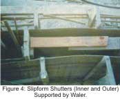 Several design considerations are taken into account for designing a slipform system. Slip forms are typically constructed of 20 mm waterproof shuttering plywood sheet & steel. Forms are coated in plastics to reduce friction and extend life of form for large pours. Forms are typically 1.2–1.5 m in height, and battered 4 mm/1200 mm vertically to reduce form friction and concrete tear out.
Jacking system supports the slipform. The jacking system resists form, platform, crew and transferred hydrostatic concrete pressures from yokes and form whalers. These pneumatic or hydraulic jacks are high capacity that is 3–25 Tonnes each. Jack placement depends on vertical forces and lateral pressures of the form. Jacks are limited by the strength of jack legs, vertical steel members placed inside form walls for vertical movement, which they ride on. Jacks are placed in such a manner that forces on the form are resisted for a uniform vertical lift.
Yoke is, upside down “U” shaped members holding slipform walls in place. It resists hydrostatic pressure of wet concrete and transfers this load onto jacks. Yokes are designed to allow clearance for workers to erect steel, vibrate and place concrete efficiently.
The assembling of vertical slipform carried out by casting the starter and checking the starter for correctness in level and diameter and chipping and making corrections, if required. Subsiquently, activities like positioning vertical and horizontal reinforcement for correct cover, fixing inside and outside staging brackets/erecting scaffold pipes and timber runners, connecting the walkway brackets and checking its level, tying vertical and horizontal reinforcement up to shutter top height, marking the position of inside and outside yokes in the starter and ensuring that three sets of yoke are located in between two tower verticals follows. It further involves assembling the inside form panel, introducing MS washers at regular intervals and fixing top and bottom waler pipes, fixing timber supports both horizontal and inclined to align the shutter, fixing the waler shoe and inside-outside yoke legs, adjusting waler shoe and checking Its verticality, keeping timber supports for waler shoe, aligning form panel by supports and fixing yoke beams one at top and another at bottom with check for verticality of yoke beam with spirit level, fixing inside and outside walkway brackets and finishing final alignment by suitably adjusting waler shoe bolts, ensuring that all walers are touching form panels, fixing the timber decking, fixing top platform pipes with pipe guides, fixing jacks and making hydraulic pipe connections, testing jacks and hydraulic pipes for leakages and replacing wherever required, fixing two sets of flying tie rod assembly, properly supporting the central ring and uniformly tightening the turn buckles located diametrically opposite, fixing tapered sleeves for jack rods, energizing slipform after filling form and removing temporary supports, fixing inside and outside hanging scaffold and doing planking and tying safety nets.
Proper concreting of slipform is essential for successful completion of the structure. Designed mix slightly sandy with round aggregate is used with ascertained initial setting time with or without retarders in accordance with atmospheric conditions and designed rate of slipform movement. Additional precautions such as proper insulation of form panels, heating system for platforms, heating of ‘mixing water’ with boilers, heating of aggregates, slowing down the lifting rate of form, heating the shutter during cold weather concreting are taken.
Concrete is delivered to the form either with the help of crane and bucket or pumping. Concrete is bucketed to hoppers on the top deck and then distributed to the form walls for placement. Concrete is pumped into a large hopper on working decks and then distributed to the form walls.
Slipform speed is determined by the amount of time the concrete in the top of the form needs before it is able to support itself and retain its shape (Camellerie, 1978). Slipforms move typically average 45 mm per hour. With advancements in jacking system, concrete mix and experience, form depths is increased by 15 mm or more and is lift at speed up to 60 mm per hour or more (Risser, 1995).
Slipform paving is most appropriate for larger projects that require high production rates. Advantages of slipform paving (ACPA, 1995) are:
Uses Low-Slump PCC Lowslump PCC of the order of 0-75 mm is necessary so that the fresh PCC is able to hold its shape once the slipform paver has passed. Low slump PCC is made with less water and usually has higher compression and flexural strengths than comparable high slump mixes.
High Productivity Large jobs generally require high production rates in order to be profitable. Slipform paving production rates are typically in the range of 65 - 100 m3/hr for mainline paving which translates into between 70 - 90 m/hr of 3.66 m wide, 250 mm thick PCC surface course.
 Smooth Riding Surface Automation and computer control allow slipform pavers to produce very smooth riding surfaces of the order of 0.90 m / km or less. The original paving stakes used for checking earth grade and placing and checking of sub-base material is not disturbed prior to starting slipform paving. This prevents any error in establishing pavement grades. The sub-base material is checked for thickness, density, line and grade prior to placing the continuously reinforced pavement steel. Once sub-base material is approved and paving is started, it is important to continually check thickness of pavement behind slipform paver, condition and location of reinforcing steel ahead and behind the Slipform paver and the edge slump while pavement is being placed. Edge slump is controlled by using a uniform mix with consistent slump and proper adjustment of edge plates on slipform pavers.
If excessive edge slump more than standard specifications is evident, either wood planks or metal forms are placed against pavement immediately and pavement brought to proper grade. Metal forms usually work better than wood planks as these lock together and do not cause variations in the pavement edge. As the paving progresses, a metal probe is inserted in the pavement to determine the thickness achieved.
The locations of key ways, tie bars, wide flange beams and super-elevations are determined in advance. These locations are adequately staked or marked. The wide flange beams at pavement ends and structures are constructed in advance of paving operations and slipform paver then paves through wide flange beams. Sand plates are required for all bar supports. Provisions are made prior to starting form less paving to take care of any sudden rain that may occur. The standard specifications require sufficient polyethylene or burlap on the job to cover such emergencies. Split header boards are used on continuously reinforced pavement so that reinforcing steel is extended past the header board at the proper elevation. The pavement standards in contract require additional reinforcing bars at each header. There is a minimum distance from the laps of the steel where a header is placed. A portable vibrator is used for vibrating the concrete adjacent to header board at the end of the day’s paving and also at the start of next day’s paving. The internal vibrators on slipform paver are unable to cover this area. Failures on continuously reinforced pavement are usually due to result of improper consolidation at the header boards or improper placement of reinforcement. Excess mortar carried by the paver is not placed in the pavement. All concrete protruding between header boards is chipped off flush with pavement face prior to the next pour
Transporting Equipment Transporting equipment is in conformance with relevant Bureau of Indian Standard or American Society of Testing and Materials (ASTM, 2004). Concrete is transported to the paving site in rear-dump trucks, in truck mixers designed with extra large blading and rear opening specifically for low slump concrete.
 Delivery Equipment As concrete transport equipment cannot operate on the paving lane, side-delivery transport equipment consisting of selfpropelled moving conveyors is used to deliver concrete from the transport equipment and discharge it in front of the paver.
Slipform Paver- Finisher Automatically controlled and crawler mounted with padded tracks slipform paverfinisher is required. Horizontal alignment is electronically referenced to a taut wire guideline. Vertical alignment is electronically referenced on both sides of paver to a taut wire guideline or to an approved laser control system.
Slipform Paving Operations Concrete Production, Transporting and Spreading
Concrete is deposited in front of the paver within 45 minutes from the time cement has been charged into the mixing drum, except that if the ambient temperature is above 32° C, the time is reduced to 30 minutes.
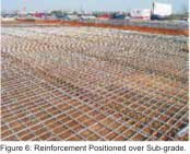
N o n - a g i t a t i n g equipment are used only on smooth roads and for haul time less than 15 minutes. No equipment is allowed to operate on the prepared and compacted underlying material in front of the paver-finisher. Equipment are allowed to operate on the underlying material only if no damage is done to the underlying material and its degree of compaction. Additional water is added to truck mixers to bring slump within specified range provided the mixture water-cement ratio is not exceeded.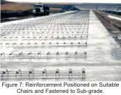 Reinforcement is positioned on suitable chairs securely fastened to the sub-grade prior to concrete placement, or may be placed on an initial layer of consolidated concrete, with the subsequent layer placed within 30 minutes of the first layer placement. If reinforcing for Continuously Reinforced Concrete Pavement (CRCP) is required, the entire operating procedure and equipment proposed is to be submitted for prior approval.
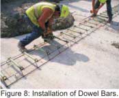 Placing Dowels and Tie Bars Dowels are installed with alignment not greater than 1 mm per 100 mm. Location of dowels is within a horizontal tolerance of plus or minus 15 mm and a vertical tolerance of plus or minus 5 mm. The portion of each dowel intended to move within the concrete or expansion cap are painted with one coat of rust inhibiting primer paint, and then oiled just prior to placement. Dowels and tie bars in joints are omitted when center of the dowel, tie bar is located within a horizontal distance from an intersecting joint equal to or less than one-fourth of slab thickness.
Contraction Joints in Steel Dowels and tie bars in longitudinal and transverse contraction joints within the paving lane are held securely in place by means of rigid metal basket assemblies. The dowels and tie bars are welded to the assembly or held firmly by mechanical locking arrangements that prevent them from becoming distorted during paving operations. The basket assemblies are held securely in the proper location by means of suitable anchors.
Installation of Dowel Bars Installation is done by bonding dowels into holes drilled into the hardened concrete. Holes approximately 3 mm greater in diameter than dowels are drilled into hardened concrete. Dowels are bonded in drilled holes using epoxy resin injected at the back of hole before installing dowel and extruded to the collar during insertion of the dowel so as to completely fill void around dowel. The dowels are held in alignment at the collar of the hole after insertion and before the grout harden, by means of suitable metal or plastic collar fitted around the dowel. The vertical alignment of dowels is checked by placing the straight edge on the surface of the pavement over the top of the dowel and measuring the vertical distance between the straight edge and beginning and ending point of the exposed part of the dowel. Where tie bars are required in longitudinal construction joints of slipform pavement, bent tie bars are installed at the paver, in front of the transverse screed or extrusion plate. If tie bars are required, a standard keyway is constructed, and the bent tie bars are inserted into the plastic concrete through a 0.45 to 0.55 mm thick metal keyway liner. Tie bars is not installed in preformed holes. The keyway liner is protected and remains in place and become part of the joint. Before placement of the adjoining paving lane, the tie bars are straightened, without spalling the concrete around the bar.
Expansion Joints in Steel Dowels in expansion joints are installed by the bonded-in-place method or by bonding into holes drilled in hardened concrete, using procedures specified above.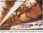 Pavements are constructed with paving and finishing equipment utilizing by slipforms. PCC is placed directly in the desired location by truck or truck attachments or fed into a placement machine for more accurate and even placement and consolidated into a more uniform and compact mass by eliminating undesirable air voids and causing it to move around potential obstructions such as reinforcing steel. Consolidation is usually accomplished using long, slender vibration rods called vibrators. The paver vibrators are inserted into the concrete not closer to the underlying material than 50 mm. The vibrators or any tamping units in front of the paver are automatically controlled so that they are stopped immediately as forward motion ceases. Excessive vibration is not permitted. Concrete in small, odd-shaped slabs or in locations inaccessible to the paver mounted vibration equipment are vibrated with a hand-operated immersion vibrator.
 The sequence of machine operations is transverse finishing, longitudinal machine floating if used, and straight edge finishing, texturing, and then edging of joints. Hand finishing is used rarely. Supplemental hand finishing for machine finished pavement is kept to an absolute minimum. Equipment to be used for supplemental hand finishing shall primarily be 3 to 4 m cutting straight edges; only very sparing use of bull floats is allowed. At no time water is added to the surface of the slab in any way, except for fog (mist) sprays to prevent plastic shrinkage cracking.
 Before concrete hardens, the surface of the pavement is given a texture. After curing is complete, all textured surfaces are thoroughly power broomed to remove all debris. Any type of transverse texturing produce grooves in straight lines across each lane within a tolerance of plus or minus 13 mm of a true line. The concrete in areas of recesses for tie-down anchors, lighting fixtures, and other outlets in the pavement is finished to provide a surface of the same texture as the surrounding area.
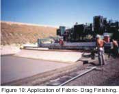
Fabric-Drag Surface Finish Surface texture is applied by dragging the surface of the pavement, in the direction of the concrete placement, with a moist fabric drag. The dragging produces a uniform finished surface having a fine sandy texture without disfiguring marks.
Broom Texturing Surface texture is applied using a mechanical stiff bristle broom drag of a type that uniformly scores the surface transverse to the pavement center line. The broom is capable of traversing the full width of the pavement in a single pass at a uniform speed and with a uniform pressure. Successive passes of the broom are overlapped minimum necessary to obtain a uniformly textured surface. The scores are uniform in appearance and approximately 1.5 mm in depth but not more than 3 mm in depth. Hand brooming is permitted only on isolated odd shaped slabs or slabs where hand finishing is permitted.
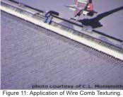
 Wire-Comb Texturing Surface texture transverse to the p a v e m e n t center line are applied using a m e c h a n i c a l wire comb drag. The comb is capable of traversing the full width of the pavement in a single pass at a uniform speed and with a uniform p r e s s u r e . Successive passes of the comb are overlapped the minimum necessary to obtain a continuous and uniformly textured surface. The scores are 2 to 5 mm deep, 1.5 to 3 mm wide and spaced 10 mm.
Surface Grooving The areas indicated on the drawings are grooved with a spring tine drag producing individual grooves 6 mm deep and 6 mm wide at spacing between groove centerlines of 50 mm. These grooves are cut perpendicular to the centerline. Before grooving begins, the concrete is allowed to stiffen sufficiently to prevent dislodging of aggregate. Grooves are not cut within 150 mm of a transverse joint or crack.
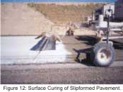
Curing is method that prevents moisture loss and supply of additional water to the PCC surface. These methods usually involve ponding water on top of a slab, continuously spraying a slab with a fine mist or covering a slab with a water-retaining material such as burlap. These methods are labor intensive and are generally not used on PCC pavements any more.
Method that prevents moisture loss but does not supply any additional water is called the Membrane Curing. These methods usually involve placing a waterproof covering over a slab such as plastic or using a liquid membrane-forming chemical compound. Curing compounds are typically formed using resins, waxes or synthetic rubbers with a dissolved volatile solvent. Once the solvent evaporates, the curing compound forms a nearimpermeable membrane over the PCC. Pigments are often added to curing compounds in order to reduce white pigment or increase dark pigment heat absorption.
Additionally, pigments allow workers to see where the curing compound has been applied, which helps to ensure complete coverage.
Longitudinal Construction Joints Dowels, Keys, and Tie bars are installed in the longitudinal construction joints or the edges are thickened. The dimensions of the keyway do not vary more than plus or minus 3 mm from the dimensions indicated and do not deviate more than plus or minus 6 mm from the mid-depth of the pavement. If any length of completed keyway of 1.5 m or more fails to meet the above tolerances, dowels are installed.
Transverse Construction Joints Transverse construction joints are installed at a planned transverse joint, at the end of each day’s placing operations and when concrete placement is interrupted. Transverse construction joints are constructed either by utilizing headers and hand placement and finishing techniques, or by placing concrete beyond the transverse construction joint location and then saw cutting full depth and removing concrete back to the transverse construction joint location. For the latter case, dowels are installed using methods for dowels installed in hardened concrete described above. All transverse construction joints are dowelled.
Expansion Joints Expansion joints are formed where indicated, and about any structures and features that project through or into the pavement, using preformed joint filler of the type, thickness, and width indicated and extends the full slab depth. Edges of the concrete at the joint face are edged. The joint filler strips are installed to form a recess at the pavement surface to be filled with joint sealant. Expansion joints are constructed with dowels thickened edges for load transfer.
Slip Joints Slip joints are installed across the full depth of the slab using expansion joint preformed joint filler material attached to the face of the original concrete placement. A reservoir for joint sealant is constructed at the top of the joint.
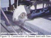
Contraction Joints Transverse and longitudinal contraction joints are of the weaken'd-plane or dummy type. Longitudinal contraction joints are constructed by sawing a groove in hardened concrete with a powerdriven saw. Transverse contraction joints are constructed in conformance with requirements for sawed joints.
 Sawed Joints Sawed contraction joints are constructed by sawing a groove in concrete with a 3 mm blade to the indicated depth. The time of initial sawing vary depending on existing and anticipated weather conditions and such as to prevent uncontrolled cracking of pavement. Sawing of the joints are commencing as soon as concrete has hardened sufficiently to permit cutting concrete without chipping, spalling, or tearing. The joints are sawed at required spacing consecutively in the sequence of the concrete placement. Sawing at a given joint location is discontinued when a crack develops ahead of the saw cut. Immediately after the joint is sawed, the saw cut and adjacent concrete surface is thoroughly flushed with water until all waste from sawing is removed from the joint. The surface is re-sprayed with curing compound as soon as free water disappears. The top of the joint opening and the joint groove at exposed edges are tightly sealed with cord or backer rod before the concrete in the region of the joint is resprayed with curing compound.
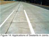
Once a joint is cut or otherwise made, it needs to be sealed to minimize water and incompressible material entry. Sealants also reduce dowel bar corrosion by reducing entrance of de-icing chemicals (ACPA, 1995). Application of joint sealants is illustrated in Figure 14, and are of three types:
Hot-pour Liquid Sealants These sealants are heated up to decrease their viscosity and then poured. Joints are ready for traffic as soon as the sealant has cooled. About 25 percent of roadway agencies use hot-pour sealants in transverse contraction joints. Most hot-pour sealants are used in longitudinal joints and low-traffic PCC pavements.
 Compression Seals These are preformed rubber compounds placed into a joint under compression. After being placed, they form a seal by pushing against each side of the joint and are immediately ready for traffic. Compression seals, commonly called neoprene seals after their primary constituent are used by about 21 percent of roadway agencies in transverse contraction joints.
Silicone Sealants These sealants are silicone polymer compounds that are poured into joints at ambient temperatures. It generally takes around 30 minutes for them to harden and make the joint ready for traffic. About 50 percent of roadway agencies use silicone sealants in transverse contraction joints.
Slipforming is a construction technique which has been used for decades for production of concrete structures. Wide range of structures are slipformed, typically, vertical structures such as towers, bridge columns and offshore platforms and horizontal structures like rigid reinforced concrete pavement, canal lining etc. Apart from vertical structures with uniform thickness, slipforming technique is also used where geometry of structure and wall thickness changes. Slipforming is a continuous working operation (24 hours a day), which requires planned supply of materials, management and supervision. Problems that occur during this process need to be solved instantly. Slipforming involves complex operations as compared to other construction techniques.
Introduction
In view of recent emphasis on infrastructure development, large volume of construction work, enormous mount of investment and accelerated development as needs at national and international level, mechnization of construction industry has become a need of the day. Slipform Technique is one of the most productive techniques for construction of Highrise structures like communication towers, chimneys, bridge piers, silos etc. Vertical Slipforming allows concrete to be erected as monolithic or cold joint structure, while reducing overall project duration. Slipform paving has enabled cement concrete road pavements, airport aprons, taxiways, runways, canal lining etc. Slipform Technique has also been successfully applied to various structures including offshore drilling platforms and nuclear facilities etc.Slipforming Technique is defined and described in various ways in literatures. According to Risser (1995) “Slipforming differs from conventional concrete forming because of the forming panels move semi continuously in relation to the concrete surface being formed and form ties are not used.” In the opinion of Camellerie (1978) “Slipforming has proved invaluable tools of construction by cutting cost and man hours and at the same time permitting construction to proceed with maximum safety.” American Concrete Pavement Association (ACPA, 1995) defined, “Slipform paving as a process used to consolidate, form into geometric shape and surface finish a Plain Concrete Cement (PCC) mass by pulling the forms continuously through and surrounding the plastic concrete mass.”
Two types of work are mainly carried out by slipform techniques, namely, Vertical Slipforming and Slipform Paving.
Vertical Slipforming
Principles of vertical slipforming are illustrated in Figure 1. The slipform panels normally have an inclination in vertical plane in order to make panel self-clearing in relation to concrete wall. The inclination depends on stiffness of the slipform panel and concrete pressure. The slipform panel has variable stiffness depending on position and dimension of each yokes and walings. Slipform operation is a continuous working process where the slipform is kept close to full of concrete while it is lifted stepwise. The concrete is placed in 100 to 250 mm thick layers whenever the freeboard height is sufficient. The slipform rate is adjusted so that initial set in concrete occur between 200 to 400 mm above bottom of the panel. Depending on inclination of panel, concrete detach the slipform panel above the hardening front where concrete skeleton is rigid enough to resist back sliding. The slipform rate is planned based on complexity of concrete structure, skills of the work force and available inventory of materials. The setting time of concrete is adjusted to fit planned slipform rate. The setting time of concrete depends on the temperature, concrete composition, and properties of the cement. Concrete setting time is adjusted by using admixtures like retarder or accelerator. Relation between concrete setting time and slipform rate is calculated by using the following equation (Foss, Kjell Tares, 2001).
VS = (h1- h2) / (ts - tt)
Where
VS = Slipform rate [mm / h]
h1 = The distance from the top of the slipform panel to the average curing front [mm]
h2 = The distance from top of the slipform panel to the average freeboard [mm]
ts = Setting time [h]
tt = Time from mixing of the concrete to placing [ h ]
Slipform temperature and transfer of heat from lower concrete layer are taken into consideration when calculating setting time for concrete. The lifting of the panel is carried out at regular intervals depending on the slipform rate. The lifting height is adjusted from 10 to 25 mm depending on desired frequency of lifting. With a hydraulic system, lifting operation is carried out by increasing oil pressure. When oil pressure is sufficient to overcome friction and weight of the form, slipform starts to lift. After slipform is lifted, the form is let down until brakes of the jacks are activated, normally 2 mm downwards.
Slipform Components and Their Functions
Yoke Legs Yoke legs are used to lift the slipform structure as one integral unit, transfer lifting reactions to jacks and acts as the main connecting member for walkway platforms, masons’ scaffold, yoke beams, top platforms, etc.Walkway Bracket (Inside and Outside) Inside and outside brackets are connected with the respective yoke legs with the help of a pin for easy erection and dismantling along with a pipe strut to support cantilever portion to facilitate placing of concrete, placing of reinforcement, vibration, fixing inserts, block outs, pockets, etc.
Shutters and Walers The function of shutters and waler assemblies is to maintain correct profile of structure to be slip formed and resist concreting pressure.
Lifting Jacks Lifting jacks facilitate lifting of Slipform assembly. Jacks are to be suitably located preferably at equal intervals to enable to lift slipform as one integral unit. Capacity of jacks is decided depending upon the reactions at point of lifting.
Jacking/Climbing Rods Jacking rods are normally located centrally in the wall to be cast or at equal distance in yoke beams depending upon the number of jacks. The jacking rods are generally of 48mm, 32mm, or 25mm in diameter based upon the capacity of jacks. The lifting jack climbs over the jack rod. The entire load of the Slipform assembly is transferred to jacking rods when jacks are energized.
Hydraulic Pump Hydraulic pumps are provided to circulate required quantity of hydraulic oil at desired pressure for energizing jacks to lift the assembly and facilitate its uniform lifting.
Tapered Sleeve Tapered sleeve tubes are provided to prevent fresh concrete coming in contact with jack rods, thus, facilitates extraction of jack rods later. Taper sleeves are attached to yoke beam and move along with slipform and create a hole in concrete around jack rod.
Over Yoke Beam
Waler Shoe Two waler shoes are provided on each of inside and outside yoke legs. Waler shoes are connected to yoke legs and waler pipes with the help of full threaded bolts. The functions of waler shoe are to adjust inclination of the shutter, adjusting the inclination of yokes and transfer reactions from waler pipes to yoke legs.
Central Ring and Tie Rod Assembly Central ring and tie rod assembly is provided to retain shape of structure to be slipformed. Central ring and flying tie rod assembly moves along with slipform.
Tapered Cross Section
There are three platforms supported on yokes. The top platform also known as “Top Deck” is used for receiving and distributing concrete, other materials and operating men, second level platform is provided inside and outside at the level of form panels to facilitate vibration of concrete, tying of reinforcement, fixing of inserts and pockets, etc. and third platform is provided below form panel for masons to finish concrete exposed from slipform shutter, to expose inserts, dowels, etc. and for curing of concrete.
Operations in Vertical Slipforming
Slipforming is not always the most efficient erection method for concrete. Each project is evaluated for suitability and economics of slipforming technology.Design and Assembly of Form and Jacks
Jacking system supports the slipform. The jacking system resists form, platform, crew and transferred hydrostatic concrete pressures from yokes and form whalers. These pneumatic or hydraulic jacks are high capacity that is 3–25 Tonnes each. Jack placement depends on vertical forces and lateral pressures of the form. Jacks are limited by the strength of jack legs, vertical steel members placed inside form walls for vertical movement, which they ride on. Jacks are placed in such a manner that forces on the form are resisted for a uniform vertical lift.
Yoke is, upside down “U” shaped members holding slipform walls in place. It resists hydrostatic pressure of wet concrete and transfers this load onto jacks. Yokes are designed to allow clearance for workers to erect steel, vibrate and place concrete efficiently.
The assembling of vertical slipform carried out by casting the starter and checking the starter for correctness in level and diameter and chipping and making corrections, if required. Subsiquently, activities like positioning vertical and horizontal reinforcement for correct cover, fixing inside and outside staging brackets/erecting scaffold pipes and timber runners, connecting the walkway brackets and checking its level, tying vertical and horizontal reinforcement up to shutter top height, marking the position of inside and outside yokes in the starter and ensuring that three sets of yoke are located in between two tower verticals follows. It further involves assembling the inside form panel, introducing MS washers at regular intervals and fixing top and bottom waler pipes, fixing timber supports both horizontal and inclined to align the shutter, fixing the waler shoe and inside-outside yoke legs, adjusting waler shoe and checking Its verticality, keeping timber supports for waler shoe, aligning form panel by supports and fixing yoke beams one at top and another at bottom with check for verticality of yoke beam with spirit level, fixing inside and outside walkway brackets and finishing final alignment by suitably adjusting waler shoe bolts, ensuring that all walers are touching form panels, fixing the timber decking, fixing top platform pipes with pipe guides, fixing jacks and making hydraulic pipe connections, testing jacks and hydraulic pipes for leakages and replacing wherever required, fixing two sets of flying tie rod assembly, properly supporting the central ring and uniformly tightening the turn buckles located diametrically opposite, fixing tapered sleeves for jack rods, energizing slipform after filling form and removing temporary supports, fixing inside and outside hanging scaffold and doing planking and tying safety nets.
Steel Deck and Elevator Erection
Deck leveling ensures that the slipform remains plumb. Total horizontal deviation at any one point is not to exceed 5 mm for structures for height of 3.0 m or less or 1/600 times height for structures greater than 3.0 m in height (Hurd, 1989). Deck level is established either with the help of a system of horizontal tubes or by laser and electronic distance meter (EDM) combination. Lasers are used to determine vertical plumb while the EDM is used to determine the elevation. Regardless of the jacking, form material, and leveling systems chosen, materials are required to be supplied to the slipform efficiently. Adequate space is provided for material lay-down and concrete receiving and distribution. Steel erection and elevator construction is done simultaneously with slipping. Elevators are erected in shafts being slipped as long as vertical tolerances are maintained. Erecting steel structure and concrete core simultaneously paves way for other activities that typically follow erection of concrete and steel.Reinforcement, Concreting, and Slipform Movement
The progress of Slipform is mainly affected by timely tying of reinforcement bars. In view of constraints of space certain precautions are considered while making schedule, for example, in view of convenience in lifting and handling the length of vertical and horizontal bars is restricted to 5 m, the diagonal bars around openings are avoided, stirrups are taken in two pieces only, alternate bars are placed nearby as substitutes for verticals in yoke beam locations.Proper concreting of slipform is essential for successful completion of the structure. Designed mix slightly sandy with round aggregate is used with ascertained initial setting time with or without retarders in accordance with atmospheric conditions and designed rate of slipform movement. Additional precautions such as proper insulation of form panels, heating system for platforms, heating of ‘mixing water’ with boilers, heating of aggregates, slowing down the lifting rate of form, heating the shutter during cold weather concreting are taken.
Concrete is delivered to the form either with the help of crane and bucket or pumping. Concrete is bucketed to hoppers on the top deck and then distributed to the form walls for placement. Concrete is pumped into a large hopper on working decks and then distributed to the form walls.
Slipform speed is determined by the amount of time the concrete in the top of the form needs before it is able to support itself and retain its shape (Camellerie, 1978). Slipforms move typically average 45 mm per hour. With advancements in jacking system, concrete mix and experience, form depths is increased by 15 mm or more and is lift at speed up to 60 mm per hour or more (Risser, 1995).
Finishing and Curing
Slipforming has two typical finishes that is wet finishing and dry finishes. A wet finish is a rubber float finish applied as the structure being slipped. Dry finishing is applied after the forms have been removed. Workers are suspended from swing stages to apply the final finish. In either case, plaster or skim coat is applied for a smooth finish. Sand blasting is not recommended for slipform concrete, usually uniform finish is difficult to achieve. Because slipform speed is determined by setting ability of concrete low slump, high early strength concrete is required for structurally adequate results. Curing is typically done before slipform dismantling Once finishing of an area is complete and the original wet finish has nearly disappeared.Slipform Paving Technique
Slipform paving is defined as process used to consolidate, form into geometric shape finish a Plain Cement Concrete (PCC) mass by pulling the forms continuously through and surrounding plastic concrete mass. Slipform paving is most appropriate for larger jobs that require high production rates.Slipform paving is most appropriate for larger projects that require high production rates. Advantages of slipform paving (ACPA, 1995) are:
Uses Low-Slump PCC Lowslump PCC of the order of 0-75 mm is necessary so that the fresh PCC is able to hold its shape once the slipform paver has passed. Low slump PCC is made with less water and usually has higher compression and flexural strengths than comparable high slump mixes.
High Productivity Large jobs generally require high production rates in order to be profitable. Slipform paving production rates are typically in the range of 65 - 100 m3/hr for mainline paving which translates into between 70 - 90 m/hr of 3.66 m wide, 250 mm thick PCC surface course.
If excessive edge slump more than standard specifications is evident, either wood planks or metal forms are placed against pavement immediately and pavement brought to proper grade. Metal forms usually work better than wood planks as these lock together and do not cause variations in the pavement edge. As the paving progresses, a metal probe is inserted in the pavement to determine the thickness achieved.
The locations of key ways, tie bars, wide flange beams and super-elevations are determined in advance. These locations are adequately staked or marked. The wide flange beams at pavement ends and structures are constructed in advance of paving operations and slipform paver then paves through wide flange beams. Sand plates are required for all bar supports. Provisions are made prior to starting form less paving to take care of any sudden rain that may occur. The standard specifications require sufficient polyethylene or burlap on the job to cover such emergencies. Split header boards are used on continuously reinforced pavement so that reinforcing steel is extended past the header board at the proper elevation. The pavement standards in contract require additional reinforcing bars at each header. There is a minimum distance from the laps of the steel where a header is placed. A portable vibrator is used for vibrating the concrete adjacent to header board at the end of the day’s paving and also at the start of next day’s paving. The internal vibrators on slipform paver are unable to cover this area. Failures on continuously reinforced pavement are usually due to result of improper consolidation at the header boards or improper placement of reinforcement. Excess mortar carried by the paver is not placed in the pavement. All concrete protruding between header boards is chipped off flush with pavement face prior to the next pour
Equipment for Slipform Paving
Batching and Mixing The batching plant is required to conform to specifications of relevant Bureau of Indian Standard or National Ready Mixed Concrete Association (NRMCA, 2002) or American Society of Testing and Materials (ASTM, 2004a). Water is not weighed or measured cumulatively with another ingredient. All concrete materials batching are desired to meet relevant Bureau of Indian Standard or ASTM C 94 requirements.Transporting Equipment Transporting equipment is in conformance with relevant Bureau of Indian Standard or American Society of Testing and Materials (ASTM, 2004). Concrete is transported to the paving site in rear-dump trucks, in truck mixers designed with extra large blading and rear opening specifically for low slump concrete.
Slipform Paver- Finisher Automatically controlled and crawler mounted with padded tracks slipform paverfinisher is required. Horizontal alignment is electronically referenced to a taut wire guideline. Vertical alignment is electronically referenced on both sides of paver to a taut wire guideline or to an approved laser control system.
Slipform Paving Operations Concrete Production, Transporting and Spreading
Concrete is deposited in front of the paver within 45 minutes from the time cement has been charged into the mixing drum, except that if the ambient temperature is above 32° C, the time is reduced to 30 minutes.
N o n - a g i t a t i n g equipment are used only on smooth roads and for haul time less than 15 minutes. No equipment is allowed to operate on the prepared and compacted underlying material in front of the paver-finisher. Equipment are allowed to operate on the underlying material only if no damage is done to the underlying material and its degree of compaction. Additional water is added to truck mixers to bring slump within specified range provided the mixture water-cement ratio is not exceeded.
Placing Reinforcing Steel
Contraction Joints in Steel Dowels and tie bars in longitudinal and transverse contraction joints within the paving lane are held securely in place by means of rigid metal basket assemblies. The dowels and tie bars are welded to the assembly or held firmly by mechanical locking arrangements that prevent them from becoming distorted during paving operations. The basket assemblies are held securely in the proper location by means of suitable anchors.
Installation of Dowel Bars Installation is done by bonding dowels into holes drilled into the hardened concrete. Holes approximately 3 mm greater in diameter than dowels are drilled into hardened concrete. Dowels are bonded in drilled holes using epoxy resin injected at the back of hole before installing dowel and extruded to the collar during insertion of the dowel so as to completely fill void around dowel. The dowels are held in alignment at the collar of the hole after insertion and before the grout harden, by means of suitable metal or plastic collar fitted around the dowel. The vertical alignment of dowels is checked by placing the straight edge on the surface of the pavement over the top of the dowel and measuring the vertical distance between the straight edge and beginning and ending point of the exposed part of the dowel. Where tie bars are required in longitudinal construction joints of slipform pavement, bent tie bars are installed at the paver, in front of the transverse screed or extrusion plate. If tie bars are required, a standard keyway is constructed, and the bent tie bars are inserted into the plastic concrete through a 0.45 to 0.55 mm thick metal keyway liner. Tie bars is not installed in preformed holes. The keyway liner is protected and remains in place and become part of the joint. Before placement of the adjoining paving lane, the tie bars are straightened, without spalling the concrete around the bar.
Expansion Joints in Steel Dowels in expansion joints are installed by the bonded-in-place method or by bonding into holes drilled in hardened concrete, using procedures specified above.
Slipform Paving, Finishing, and Texturing
Fabric-Drag Surface Finish Surface texture is applied by dragging the surface of the pavement, in the direction of the concrete placement, with a moist fabric drag. The dragging produces a uniform finished surface having a fine sandy texture without disfiguring marks.
Broom Texturing Surface texture is applied using a mechanical stiff bristle broom drag of a type that uniformly scores the surface transverse to the pavement center line. The broom is capable of traversing the full width of the pavement in a single pass at a uniform speed and with a uniform pressure. Successive passes of the broom are overlapped minimum necessary to obtain a uniformly textured surface. The scores are uniform in appearance and approximately 1.5 mm in depth but not more than 3 mm in depth. Hand brooming is permitted only on isolated odd shaped slabs or slabs where hand finishing is permitted.
Surface Grooving The areas indicated on the drawings are grooved with a spring tine drag producing individual grooves 6 mm deep and 6 mm wide at spacing between groove centerlines of 50 mm. These grooves are cut perpendicular to the centerline. Before grooving begins, the concrete is allowed to stiffen sufficiently to prevent dislodging of aggregate. Grooves are not cut within 150 mm of a transverse joint or crack.
Moist or Membrane Curing
Concrete is continuously protected against loss of moisture and rapid temperature changes for at least 7 days from the completion of finishing operations. Unhardened concrete is protected from rain and flowing water. During hot weather with low humidity and/or wind, the measures to prevent plastic shrinkage cracks from developing are taken. Plastic shrinkage cracks that occur are filled by injection of epoxy resin after the concrete hardens. Plastic shrinkage cracks are never troweled over or filled with slurry. Generally, curing is accomplished by one of two methods.Curing is method that prevents moisture loss and supply of additional water to the PCC surface. These methods usually involve ponding water on top of a slab, continuously spraying a slab with a fine mist or covering a slab with a water-retaining material such as burlap. These methods are labor intensive and are generally not used on PCC pavements any more.
Method that prevents moisture loss but does not supply any additional water is called the Membrane Curing. These methods usually involve placing a waterproof covering over a slab such as plastic or using a liquid membrane-forming chemical compound. Curing compounds are typically formed using resins, waxes or synthetic rubbers with a dissolved volatile solvent. Once the solvent evaporates, the curing compound forms a nearimpermeable membrane over the PCC. Pigments are often added to curing compounds in order to reduce white pigment or increase dark pigment heat absorption.
Additionally, pigments allow workers to see where the curing compound has been applied, which helps to ensure complete coverage.
Construction Joints and Their Sealing
All joints are straight, perpendicular to the finished grade of the pavement, and continuous from edge to edge or end to end of the pavement with no abrupt offset and no gradual deviation greater than 13 mm.Longitudinal Construction Joints Dowels, Keys, and Tie bars are installed in the longitudinal construction joints or the edges are thickened. The dimensions of the keyway do not vary more than plus or minus 3 mm from the dimensions indicated and do not deviate more than plus or minus 6 mm from the mid-depth of the pavement. If any length of completed keyway of 1.5 m or more fails to meet the above tolerances, dowels are installed.
Transverse Construction Joints Transverse construction joints are installed at a planned transverse joint, at the end of each day’s placing operations and when concrete placement is interrupted. Transverse construction joints are constructed either by utilizing headers and hand placement and finishing techniques, or by placing concrete beyond the transverse construction joint location and then saw cutting full depth and removing concrete back to the transverse construction joint location. For the latter case, dowels are installed using methods for dowels installed in hardened concrete described above. All transverse construction joints are dowelled.
Expansion Joints Expansion joints are formed where indicated, and about any structures and features that project through or into the pavement, using preformed joint filler of the type, thickness, and width indicated and extends the full slab depth. Edges of the concrete at the joint face are edged. The joint filler strips are installed to form a recess at the pavement surface to be filled with joint sealant. Expansion joints are constructed with dowels thickened edges for load transfer.
Slip Joints Slip joints are installed across the full depth of the slab using expansion joint preformed joint filler material attached to the face of the original concrete placement. A reservoir for joint sealant is constructed at the top of the joint.
Contraction Joints Transverse and longitudinal contraction joints are of the weaken'd-plane or dummy type. Longitudinal contraction joints are constructed by sawing a groove in hardened concrete with a powerdriven saw. Transverse contraction joints are constructed in conformance with requirements for sawed joints.
Once a joint is cut or otherwise made, it needs to be sealed to minimize water and incompressible material entry. Sealants also reduce dowel bar corrosion by reducing entrance of de-icing chemicals (ACPA, 1995). Application of joint sealants is illustrated in Figure 14, and are of three types:
Hot-pour Liquid Sealants These sealants are heated up to decrease their viscosity and then poured. Joints are ready for traffic as soon as the sealant has cooled. About 25 percent of roadway agencies use hot-pour sealants in transverse contraction joints. Most hot-pour sealants are used in longitudinal joints and low-traffic PCC pavements.
Silicone Sealants These sealants are silicone polymer compounds that are poured into joints at ambient temperatures. It generally takes around 30 minutes for them to harden and make the joint ready for traffic. About 50 percent of roadway agencies use silicone sealants in transverse contraction joints.
References
- American Concrete Pavement Association (ACPA), (1995), Construction of Portland Cement Concrete Pavements. National Highway Institute Course No. 13133. AASHTO/FHWA/Industry Joint Training. Federal Highway Administration, Department of Transportation. Washington, D.C.
- ASTMC 494/C 494 M (2004), “Chemical Admixtures of Concrete” American Society of Testing and Materials.
- ASTMC 94/C 94 M (2004a), “Ready Mixed Concrete,” American Society of Testing and Materials.
- Camellerie, J. F.( 1978) “Vertical Slipforming as a construction tool,” Concrete Construction, May.
- Fossa, Kjell Tares( 2001) “Slipforming of Vertical concrete structure, friction between concrete and slipform panel,” Narwegian University of Science and Technology Library.
- NHRMCA CPMB 100 (2002), “Concrete Plant Standards,” National Ready Mixed Concrete Association.
- Hurd, K. M (1989) “Formwork for concrete 5th Edition,” Detroit – American Concrete Institute.
- Risser, Bob(1995) “Advances in vertical slipform construction” Concrete Construction, October.
- Sanjay Chandra(1997) “Slipform Technique–A Productivity Study,” P.G. Dissertation, Madhav Institute of Technology and Science, Gwalior( India).
- “Slipforming,” Scanada Slipform System, Inc.
- “Slipforming Every Inc.”
NBM&CW May 2007