Seismic Analysis & Design Features in STRUDS
Sampada Palashikar, Technical Support Engineer - SoftTech Engineers Pvt Ltd, Pune
Structural design of earthquake resistant buildings has almost become mandatory now all over India. As such, we've implemented relevant clauses of IS:1893 (2002) and IS:13920 applicable for RC buildings in STRUDS. The intention is to provide a fast and reliable tool to structural engineers using which they can off-load the arduous task of cumbersome calculations to STRUDS and at the same time can apply their own good judgment for interpretation of results to provide appropriate practical design & detailing for all components of buildings like slabs, beams, columns and foundation. The best part of STRUDS is that, it calculates the EQ loads automatically from the basic parameters provided by user, unlike many other software, where user has to calculate & apply the horizontal loads on the space frame manually.
Generation of Earthquake Loads
User has to provide only the basic parameters in a single window from which STRUDS automatically calculates the EQ loads on the structure. The generation of EQ loads can be done by any of the methods mentioned below:(1) Frame stiffness Basis– Direct Analysis
In this method, stiffness of a frame is calculated by applying a unit load at the top of the each Plane Frame (Top floor is specified by user, otherwise program assumes the default top floor). Then the base shear is distributed in proportion to the relative stiffness of the frames. This Base Shear is distributed at floor levels as per the IS:1893 (2002). When the frames in both X and Y direction are properly formed, this method accurately computes EQ loads.(2) Generate EQ Load– Column Reaction Basis
(3) Generate EQ Load–Response spectrum method
In this method, the EQ load is generated dynamically by Response Spectrum method. In this method, the response of the structure is worked out for the number of modes, as given by the user, and then the design forces are combined as specified in the relevant clauses of IS:1893(2002). This happens in following steps: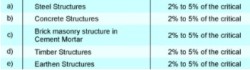
- Lumped mass generation
- Frequency calculation
- Time period calculation
- Calculation of base shear as per given spectra and time period for particular mode shape
- Super imposition of base shear of all mode shapes using SRSS method.
Provisions of IS:1893 Codes
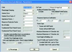
STRUDS has the options of performing Response Spectrum analysis according to the provisions of previous IS:1893(1984) as well as the revised IS:1893(2002). This option enables the user to select the relevant code for the analysis. Sometimes structural engineer needs to check the design calculations for an existing building where seismic analysis was done as per previous code. In such a case, user can choose the previous code.Percentage Damping
The effect of internal friction, imperfect elasticity of the material, slipping, sliding, etc in reducing the amplitude of vibration and is expressed as a percentage of critical damping.The code does not provide explicit specification of damping for buildings. However, Appendix F of the code indicates the following values of damping for different types of structure.
User can specify the Damping factor for the entire structure in the basic parameters window. The default value of damping in STRUDS is 5% of the critical damping.
Seismic Zone
On the basis of the past recorded seismic history, as well as the probability of occurrence of future earthquake, the Indian subcontinent has been broadly subdivided into four seismic Zones (Zone II, III, IV, and V). Zone II has the least probability of occurrence of earthquakes of high magnitudes, whereas the Zone V has the maximum probability of occurrence of earthquakes of high magnitude, due to which there may be heavy loss of life and property. User can select the seismic zone in the basic parameters window.Seismic Zone Factor
Depending upon the geographical location and the Seismic Zone in which the structure exists, these are the multiplying factors to be used with average spectra for response spectrum approach. The values of the seismic zone factors are automatically updated on change of the Seismic zone, however, if the user desires, the default value could be over written in the basic parameters window.Importance Factor
Depending upon the functional use of the structure as well as the hazardous consequences in the event of the failure, the Importance factor is assigned to every structure. This is specified so that important structures such as hospitals, government offices, airports etc should withstand even if rest of the buildings have suffered major damages due to an earthquake.Gamma
This factor is used for the combination of shears for all the modes. For building of intermediate height, value of Gamma may be obtained by linear interpolation. STRUDS sets the default value for gamma according to height of the structure, but user can change it in the basic parameters window.Modes
The number of modes to be used in the analysis should be such that the sum total of modal masses of all modes considered is at least 90 % of total seismic mass. As per IS codal provisions, at least three modes of response of the structure should be considered therefore the default number of modes is 3 in STRUDS. User can however, increase the number of modes to achieve 90% participation of modal masses.Soil Type
IS:1893(2002) introduces a new factor to indicate the soil type on which the structure stands, in place of the soil foundation factor, Gama, which existed in IS:1893(1984).IS:1893(2002), now broadly classifies the soils into three categories, that is Rocky or Hard soils, Medium soils, and Soft soils. This factor enables the user to make the necessary selection in the basic parameters window.
Beta
Beta is the soil foundation factor, as defined in IS:1893(1984). This factor no more exists in I.S IS:1893(2002).Response Reduction Factor
This factor depends on the perceived seismic damage performance of the structure, characterized by ductile or brittle deformations. The ratio (I/R) shall not be greater than 1.0. For structures having ductile detailing, the Response Reduction factor is higher and vice versa.Fundamental Time Period
It is calculated by STRUDS internally using clause 7.6.1 of IS:1893(2002).Scaling of Dynamic Base Shear
As per clause number 7.8.2 of IS:1893(2002), if we generate earthquake loads by response spectrum method, the design base shear (VB)dynamic shall be compared with a base shear (VB)static calculated by using a fundamental period Ta, where Ta is as per clause 7.6 where (VB) dynamic is less than(VB)static, all the response quantities (Member forces, displacements, story forces, story shears and base reactions) shall be multiplied by (VB)static / (VB)dynamic. In STRUDS, an option is provided to consider this clause or not to consider. If considered then whether the factor to be calculated internally or will be given by user can be chosen.Response Spectrum Coefficients
These are the response spectrum factors along the x, y and the z direction. The default value in STRUDS is 1. We can select frame type as Moment Resistance Frame (i.e. Framed structure with or without Infill Panels (i.e. Framed structure without Shear walls and bracing or Other Frame (i.e. Framed structure with Shear walls and bracing.). The user can select the type of wall load transfer on to the floor. If the first option, that is "Consider Half Wall load on Floor" is checked, half the wall load will be distributed to the floor above, and half the wall load will be transferred to the floor below. In the other case, that is "Consider Total Wall Load on Floor" the entire load of the wall will be transferred to the floor below, for the purpose of seismic load computation.Torsional Effect due to the eccentricity between the Centre of Mass and the Centre of Stiffness can be automatically taken into account in STRUDS.
The Floor Diaphragm Action, constitutes, one of the most important features of STRUDS, for he earthquake load generation. If this option is selected, the effect of the slab rigidity is taken into account for the calculation of earthquake forces. In this case, a floor node is created at every defined floor level. The rotation about the Global Z axis(theta z), remains constant for all the nodes at a floor level, whereas the other two degrees of freedom, namely translation along the Global X and Y axes(u, v) at all the nodes, can be correlated, with the displacements at the defined Floor node. Consideration of the rigid diaphragm effect gives a better picture of the distribution of the seismic forces.
The LL percentage dialog box enables you to specify the different Live Load percentage at each floor level. The user can either numerically specify a constant live load at all floor levels except the terrace level where the L.L percentage is taken as zero as per I.S 1893:2002, by checking the option ‘Consider constant L.L percentage at all floors', or he can manually edit the L.L percentages at various floor levels.
Soft Storey Effect
The user can account for the Soft Storey effect in STRUDS for Seismic analysis. However, the storey, which is to be declared as a Soft Storey, needs to be defined explicitly by the user. In STRUDS, user would need to define the upper level as well as the lower level of the soft storey, as well as the factor, by which the end actions for all the members of this soft storey would need to be modified. Once, you have done this, the beams at the upper and lower level, as well as the columns in between these two levels, will be designed for the elemental end forces obtained in the analysis multiplied by the factor, which you have specified.Cantilever Projections
In STRUDS, when the EQ loads are generated for the modeled structure, by any of the methods available for EQ load generation, these act, in the horizontal direction, that is in the X+, X-, Y+, and the Y- directions. However, if you want to specifically consider the EQ loads acting in the vertical directions, as in horizontally projecting cantilever balconies, STRUDS provides you the facility to declare these elements on which the Vertical EQ loads are to be considered, as horizontal cantilevering elements. Once, user has declared these elements, as Horizontal Cantilevers, while designing such elements, depending upon whether the design load combination involves the EQ loads, they would be designed for Vertical EQ loads also as per relevant clause of IS:1893–2002, wherein the design forces are computed as given below:The total seismic weight W, acting on the cantilever beam is given as,
W = [Sum of all Elemental Dead loads] + [ (Live load reduction factor at the set floor level) * (sum of all Elemental Live Loads)] + [Dead load reaction of Cross Beam] + [(Live load reduction factor) * (Live load reaction of Cross Beam)]
This load is assumed to act at the center of the cantilever beam.
The total design vertical seismic force is given as
V = (10/3) * Ah * Total Seismic weight
However, declaring these elements as cantilevers, will not affect the analysis results at all, and the cantilevering effect will be taken into account only for design.
EQ Load Report
STRUDS generates a detail Seismic Load generation report giving stepwise calculations for: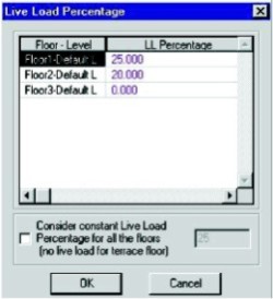
- Earthquake load parameters
- Floor wise lumped loads on column / shear wall nodes
- Frequency Time Period and % Mass Participation (Eigen value Analysis)
- Mode Shape coefficient (Eigen Vector)
- Scale factor calculation based on static and dynamic base shear calculation
- Floor wise distribution of base shear
- Distribution of floor base shear to column and shear wall nodes
- Contribution of shear walls and column in Eq. resistance of building.
Ductile Detailing in Beams and Columns
STRUDS has the option while deciding the design parameters for this purpose on both beam and column tab. If user has generated the earthquake load and have selected either Plane Frame or Space Frame method for analysis and design, he can select the check box to apply the detailing in beam or column reinforcement as per IS 13920 code. The stirrup spacing and minimum steel criteria as per the code will be complied while providing reinforcement in the columns.Confinement Reinforcement
This option is activated, only if user chooses the option for detailing as per I.S 13920. If this option is selected Confinement reinforcement will be provided at both the junctions of the Column and Beam. The details pertaining to this, in terms of the Length and Spacing of the Confinement Reinforcement will be displayed in the detailed Design Report by STRUDS.SUMMARY
All relevant clauses of IS: 1893(2002) & IS: 13920 are implemented in STRUDS so that a structural engineer can analyze, design and detail a RC building for seismic resistant design. Utmost care is taken for generation of EQ loads and provision of drawings with ductile detailing. Generation of EQ loads is automatic and step by step calculation report brings transparency in analysis and design calculations of STRUDS.
Published on:
01 January 2009
Published in: NBM&CW August 2008
Share:
We Value Your Comment