Computer Application in Underground Storage Structures
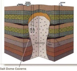
The technique of storing gases other than air in man made cavern has a short history. Gas in nature is safely residing for millions of years under good competent rock. Underground storage of natural gas was first practised in 1915 in North America in converted oil and gas fields. At a later stage, storage space was created by injecting gas into water filled rock formations (aquifers) located below good quality rock. From a first few Liquefied Natural Gas (LNG) installations in caverns without wall protection or ground water control, gradually more efficient storage systems were developed using water curtains and refrigeration. Today’s development in the field of storage of gases in rock caverns is concentrated to efficient small scale Liquefied Petroleum Gas (LPG) storage and to natural gas storage. The main reason to this being safety and public acceptance. But the high vapour pressure of LPG means deep location of the cavern and its stability. However, the complicated and fractured rock formations which are usually encountered while constructing such cavern need careful analysis and design.
The stability of a rock cavern is more or less dependent upon the strength of the rock formation and the state of rock stress around the cavern i.e. the ratio of horizontal to vertical rock stress. The strength of the rock formation is governed by the strength of its discontinuities, joints or bedding planes and never is overlooked while analysing a rock cavern. The paper focuses on the stressdeformation response of a twin tunnel constructed with different diameters at different spacing subjected to different internal pressures through a discontinuum analysis carried out using UDEC.
Need for Underground Storages
LPG has successfully been stored underground in unlined rock caverns for the last three decades.LPG is either stored at nearly atmospheric pressure at low temperatures (refrigerated storage) or pressurised at ambient rock temperature (pressurized storage). The containment of both is controlled by the ground water in the rock fracture network surrounding the cavern. In order to secure containment the storage must be located at a sufficient depth below the ground water surface. Liquefied petroleum gases are a mixture of propane and butane with various compositions and properties. Pure propane may be stored as LPG at –42°C at atmospheric pressure in a fully refrigerated storage. Any temperature increase will induce boiling, which will continue until the pressure reaches a value that matches the vapour pressure curve for propane. In the refrigerated storage, the containment of LPG is secured by the water saturated frozen zone surrounding the caverns and the free water that must be allowed above the 0°- isotherm. If LPG is to be stored in a fully compressed storage, the required pressure, i.e., the required depth below the ground water table is determined by the storage conditions of the product and the ambient rock temperature. Containment must be ensured at all time for economical, safety and environmental reasons and therefore the gas must be stored at pressures below its critical pressures taking into account the influence on geometric factors such as shape, dimensions and number of parallel caverns etc. In general the required location depth for pressurized storage is greater than that of refrigerated.
The storage conditions for natural gas are much more extreme than those for petroleum gases. The gas is either stored at extremely high pressures in the gas phase as compressed natural gas (CNG) or in liquid state as LNG. CNG can be stored in either Lined Rock Caverns (LRC) or in deep, large and water-sealed unlined caverns (hydraulically compensated). The containment principles for the unlined alternative are comparable to the compressed LPG storages. However, in order to increase the storage density and storage volume the gas may be stored in the cavern excavated deep below the ground water table. Alternatively, the gas may be stored in LRCs at more moderate depths. The LRCs may be constructed for pressures up to 200 bar, increasing the density about 200 times, with a rock cover of only 100 to 200 metres. The wall structure of thick steel, concrete and drainage system and its interaction with the bedrock is designed to contain the gas and bear the pressure. Maximum storage pressure is stipulated by the rock mass condition, the deformability and its interaction with the lining system.
Advantages of Underground Storages
- Costs for firefighting equipment are relatively low.
- Land costs are relatively low because of the reduction or elimination of buffer zones.
- Visual impact is low, since there are no bulky storage vessels on the surface.
- Reduced exposure to damage, explosion risk and land requirement
- Benefits of economies of scale
- Better use of land space
- Strategic storage of essential products
- Better environmental quality
- Reduced reliance on foreign import
- Improved energy efficiency
- Better use of material resources
- Better safety and protection
- The construction cost for storing about 2,00,000 m3 in the underground rock cavern is cheaper than the surface tank storage.
- The risk of oil leaking out and polluting the ground water is less.
- Underground storages can be located in earthquake zones.
Cavern Geometry
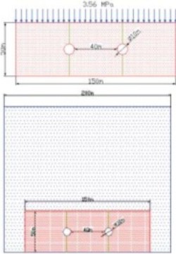
A twin circular tunnel of 7.5 m, 10 m and 12.5 m diameters placed at a depth of 150 m spaced at different clear distances varying from 1D to 4D (D – Diameter of the tunnel) has been considered for the analysis. The rock formation is considered to be intact with a single vertical joint passing through the centre of the tunnels. The cavern geometry is shown in Figure 1.Material Properties
Intact Rock Properties:Unit weight=27.23 kN/m3, Bulk modulus=20000 MPa, Shear modulus=21818 MPa, Friction angle=35°, Cohesion=2.3 MPa
Joint Properties: Joint normal stiffness=12000 MPa/m, Joint shear stiffness=1200 MPa/m, Friction angle=22°, Cohesion=0.5 MPa
Software Used
Analysis
The parametric study on the twin circular tunnel consists of three variables: a) Diameter of the tunnel viz. 7.5 m, 10 m and 12.5 m b) Clear distance between the tunnels viz. 10m, 20m, 30m and 40m c) Internal pressures in the tunnel viz. empty, 1.5 MPa, 3.0 MPa and 4.5 MPa. The effect of clear distance between the tunnels and the effect of increase in internal pressure in the tunnel, on the stress distribution-around the tunnel, at the crown and at the springing levels are analysed. The deformations at these places are also studied.In order to have an in-depth study of the above parameters, from the problem geometry shown in Figure 2, a block of 150 m ´ 50 m around the twin circular tunnels has been chosen for finer zoning of the tunnel region. An overburden of 125 m of rock mass has been simulated by applying a uniform vertical stress of 3.56 MPa on the upper boundary of the problem geometry. The value of 3.56 MPa has been obtained by analyzing the complete problem geometry shown in Figure 2 under self weight.
Results and Discussions
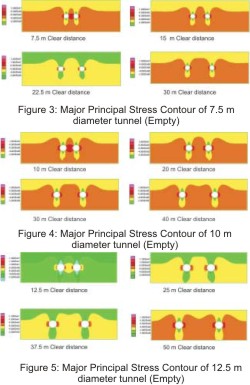
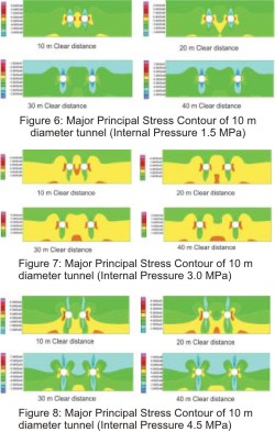
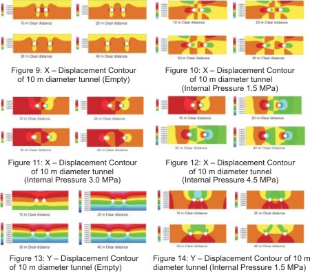
The stress–deformation response of the twin tunnel system with varying diameters and under different pressure conditions has been the main focus of the present study. The major principal stresses (s1) contours of the empty tunnel of varying diameter are presented in Figures 3 to 5.A critical study of the stress distribution around the tunnel system leads to a general conclusion that as the spacing between the tunnels increases, the stress distribution on the inner and outer side of the tunnel more or less tends to become identical, especially at a spacing of 4D. This implies that when the tunnels are in close proximity to each other there is interference among them which results in unequal stress distribution on both the spring lines. This interference decreases as the spacing among the tunnel increases. The detailed analysis of the pressurized tunnel indicates that with the increases in internal pressure the difference in the measured stresses at the inner and outer spring lines increases, the phenomenon being more pronounced when the tunnel spacing is less. The minor principal stress contours also indicates that there is virtually no interference among the tunnels at a spacing of 4D. Since the response of the tunnel is similar irrespective of the diameter of the tunnel, the major principal stresses contours, Xdisplacements contours and Y – displacement contours of the 10 m diameter tunnel only are presented in this paper as Figures 6 to 14.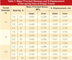
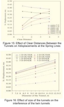
It may be noted from the table that the percentage variation in the values of the X-displacements of the tunnels spaced at 1D and 2D is 30 %. As the spacing increases from 1D to 4D, the percentage variations also increases from 30% to 55%, 70% and 81% respectively. It may also be noted that the difference in the size of the tunnel do not have any major influence on the behavior of the tunnel. The increase in the diameter of the tunnel results in slight increase in the X-displacement but very marginal percent variation only. It will be very preliminary to state that the size of the tunnel does not have any influence on the interference of the tunnels. A detailed analysis is required to be carried out for confirming this behavior.
The graphical representation of the clear distance and the X-displacement presented at Figure 15 clearly indicates the effect of Clear Distances between the tunnels on X-displacements at the Spring Lines in case of empty tunnel. Figure 16 indicates the effect of size of the tunnel on the interference of the twin tunnels.
Conclusion
- As the internal pressure increases, the zone of higher major principal stresses at the crown increases and at the springing level decreases.
- The major principal stresses are maximum at the crown and the invert of the tunnel. Therefore, these positions of the tunnel have to be critically examined for designing LPG Storage averns.
- Taking the major principal stresses at the crown and the invert level as the deciding criteria, theminimum critical distance to be maintained between twin circular tunnels should be 4D for invalidating the effect of interference of tunnels.
- Generally, the increase in internal gas pressure of the tunnel increases the X-displacement at the crown and springing levels.
- The displacements at the crown in the X-direction indicate that the minimum critical distance to be maintained between twin circular tunnels should be 3D for invalidating the effect of interference of tunnels.
- The increase in internal gas pressure of the tunnel decreases the Y-displacement at the crown and springing levels.
- The displacements at both the springing levels indicate that the minimum critical distance to bemaintained between twin circular tunnels should be 4D for invalidating the effect of interference of tunnels.
References
- H.Larsson, R.Glamheden and G.Ahrling (1989). Storage of Natural Gas at High Pressure in Lined Rock Caverns- Rock Mechanics Analysis, Proceedings of International Conference on Storage of Gases in Rock Caverns, Trondheim. pp. 177-184.
- Itasca C.G. Inc. (1999) Universal Distinct Element Code (UDEC) User’s Manual, Version 3.10,Minneapolis.
- N.Barton, K.Monsen, P.Chryssanthakis and O.Norheim (1989). Rock Mechanics Design for High Pressure Gas Storage in Shallow Lined Caverns, Proceedings of International Conference on Storage of Gases in Rock Caverns, Trondheim. pp. 159-176.
- R.S.Arya, J.B.Maheshwari, R.Chalisgaonkar, A. K. Mittal and G.C.Saxena (1995). Finite Element Analysis of Underground Twin Cavities – A Study, Proceedings of Conference on Design and Construction of Underground Structures, New Delhi. pp. 251-260.
Published on:
06 January 2009
Published in: NBM&CW August 2007
Share:
We Value Your Comment