Precast RCC Structures versus Pre-Engineered Steel Structures

Construction projects like pre-engineered structures use different innovative methods to reduce the construction period and increase their efficiency. Generally, construction of industrial buildings comprise steel structures rather than concrete. However, their disadvantages are shortage of skilled labors at site, inter-dependency of steel erection, poor fire rating properties of steel buildings and their periodic maintenance.
Precast technology provides productive construction management such as decreasing the construction period and saving labour cost, because high-quality standardized elements are produced in plants and thereafter put together at construction sites. The technology provides new construction techniques for speedy erection of structures.
In this research, different long span floor systems have been studied. A model is prepared on ETABS for an industrial building (warehouse) spanning 40x100m. The parametric comparative study is performed on mathematical models with different precast elements and steel elements to evaluate their performance with regards to displacement, time/period, modal mass participating ratios, different response plots like storey shears, base shear, maximum storey drift etc. This study also presents the design approach to different precast connections. Cost and time comparison is made between the precast RCC and pre-engineered steel structure.
Introduction
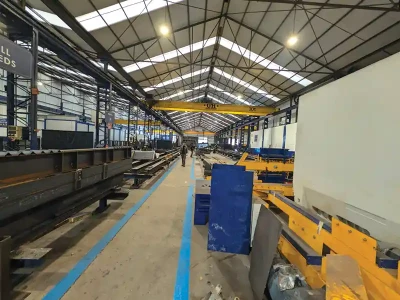
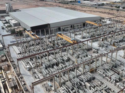
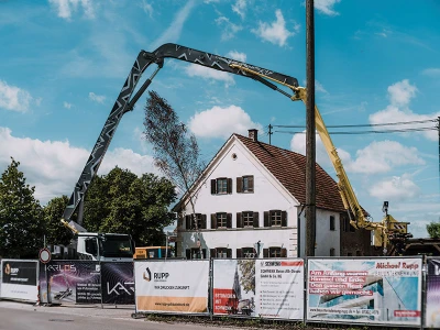
 Prestressed Precsat Hollowcore slabs over structural stel frames
Industrial Structures: Industrial structures are mostly designed to store raw materials or goods and support manufacturing. Some of the requirements for industrial building are:
- More column-free spaces to utilise full area.
- The floor-to-floor height desired is high in comparison to conventional RCC buildings.
- High span structures.

Precast concrete: Precast construction involves casting of standardized concrete slabs, beams, and columns, in a reusable mould, in a preferable environment, and transported to the project site, where they are assembled. On the contrary, standard concrete is poured into site-specific moulds and cured on construction place. Precast stone is differentiated from precast concrete as they use fine aggregates, so the final unit appears like natural stone. The moulds used in a precast plant can be reused a number of times before they have to be replaced, often making it cheaper than onsite casting when looking at the cost per unit of formwork.
Precast slabs: Precast concrete slab systems are made of a wide variety of precast concrete elements, such as hollow core slab, double T-slabs, solid slabs, and inverted T-beam, L shaped beams, rectangular shaped etc. These elements can also be used in combination with steel beams and cast-in-place concrete topping in some applications to satisfy design requirements. These prestressed floor slabs are generally used for general structural engineering like residential and industrial constructions, multi-storey car parking lots, hotels, supermarkets shops, etc with span widths between 8 - 20m.
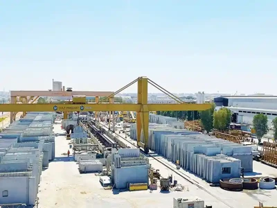
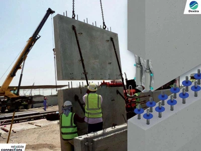
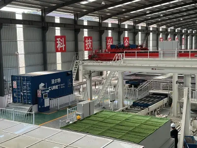
Precast frame for Industrial structure

Objectives
- To design a long span floor system utilizing floor elements viz., hollow core slab, double Tee slab for both Precast RCC frame and Structural Steel frame.
- To study the behaviour and response of the building in terms of base shear, storey drift, time period.
- Analysis and design of an industrial building (warehouse) by using precast slabs.
- To compare displacement, axial forces, bending moment obtained in the two models.
- Cost comparison of Precast RCC vs Structural Steel frame building using precast hollow core slabs
Subramani T. (2018); Analysed and designed a G+6 storey residential building using finite element software ETABS. Equivalent static analysis and response spectrum analysis method were considered and found out the results such as base shear, modal participation mass ratios, storey response plots etc. It is concluded that deflection is more in precast structure when compared to conventional RCC structure but the use of precast concrete construction can significantly reduce adverse environmental impacts at site, enhance quality control, reduce the amount of site labour and amount of construction waste generated on sites.[7]
Arjun T N et.al., (2018): Investigated the structural behaviour of Precast-Prestressed slabs for multi-story buildings and compared the results with conventional RCC slab systems. The main advantage of the Precast-Prestressed concrete slab is to bring down the dead weight of the screed floor system, increase its strength and improve its aesthetic appearance. The paper analysed the effect of two different slab systems on the G+3 building frame and compared the results. The Precast-Prestressed slab system was found to be structurally stronger than the conventional slab system.[8]
Lavitha V, (2015): In this recent research, G+6 storey RCC and Steel framed structure were analysed by equivalent static method considering seismic zone IV. In RCC frame, all structural elements were designed according to IS 456:2000, steel members were designed according to IS 800:2007 and steel table. Fundamental time period for RCC structure was found out to be more when compared to the steel frame due to higher mass concentration of RCC framed structure. It was finally concluded that steel’s strength, ductility together with the design, makes it safe in higher seismic zones for higher performance of the entire structure [9].
Mr. Anil S. Savadi., (2014): Composite concrete structure, RCC structure, steel structure frames were taken for comparative study of 3 storey industrial structure located in zone III of IS1893-2016. Equivalent static analysis method was utilized for modelling of composite, RCC and steel building; Finite element software STAAD-pro V8i was used. The result depicts that the cost of the composite structure was less when compared to steel and RCC structure. It was concluded that composite structure is the best to be opted for the multi-storeyed building [10].
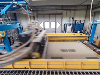
 Figure 4.1.1: Front side Elevation and section of the plan
Methodology
Buildings for the industrial sector demand for large column free spaces within the building. Two models have been created for research study, viz:
- One model is with the large column free spaces duly connected with precast RCC columns, beams and hollow core slabs placed on top of the beams.
- In the second model, the structural steel for frames viz., columns and beams are considered with floor system as precast hollow core slabs.Two alternatives will be studied for the roofing system, viz:
- Prestressed precast hollow core slab, double T-slabs as roofing elements.
- With steel beams and columns, considering hollow core slab as roofing element.
Description and data of the structure
Plan dimensions: 40× 100 m Total height: 13.9m
Storey heights: Plinth-1.5m, First floor-4.8m, Terrace-4.6m, Headroom-3m,
Concrete grade: M40, M25, Grade of longitudinal bars: Fe500 Grade of confinement bars: Fe 415

Structural configurations for precast RCC structure
Size of columns: 400×600mm, 400× 1000mm, 600×300mm.
Size of beams: 600×200mm, 230× 600mm, 300×450mm, 400×600mm.
Hollow core slab thickness: 200mm + 75mm topping, One way slab: 225mm.
Shear wall thickness: 250mm.
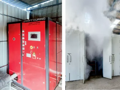
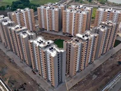
 Figure 4.2.2: view of the industrial building
 Structural configurations for PEB structure
Up to Plinth, RCC column sizes: 600×600mm.
Plinth level RCC beams: 230×400mm, 400×600mm.
Steel column size: Hollow box section of size 400×400×12.5mm
Steel beams: UKB610×229×125, UKB 533×312×272.
Hollow core slab thickness: 200mm
+75mm topping, One way slab: 225mm.
Expansion Joints
An expansion joint is provided in concrete to allow for the movement of structural elements due to temperature, moisture & other changes. It allows concrete structure to expand or contract due to thermal variation without causing stress, which will reduce the cracking in a building. If an earthquake occurs, the long structure act as a two or more different structures due to expansion joints.
When the length of buildings exceeds 45m, it is necessary to use one or more expansion joints in concrete. (Clause 27.1 and 27.2 - IS 456-2000) and Table 2 of IS 3414-1968 gives recommendation for spacing of expansion joints.
The expansion joint calculation in building is explained below:
(a) Case-1: When floor level of the adjacent units of a building or buildings are at the same level.
Expansion joint = (R1∆1 + R2∆2) /2
(b) When floor level of the adjacent units of a building or buildings are not at the same level.
Expansion joint = (R1∆1 + R2∆2)
Where, R1 & R2 is the Response reduction factor as per IS-1893 for each building and,
∆1 & ∆2 is the deflection of building due to lateral force (earthquake force)
(As per IS 1893-2016 Clause 7.11.3)
Equivalent hollow core slab thickness
Equivalent depth for slab of 200mm
Jointed weight for DP6-200 = 2.76kN/m2
2.76= D X 25
D= 0.1104m = 110mm
Thickness of toppings on the slab= 75mm
Total equivalent thickness to be substi- tuted in ETABS = 110+75 = 185 mm
The slab would be spanned in one way load distribution.
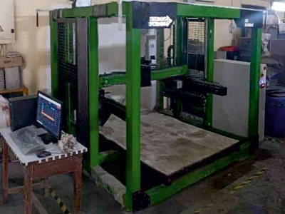
 Figure 4.6.1: Hollow core slab
Load calculations
DEAD LOAD: Its self-multiplier is taken as 1 in ETABS.
LIVE LOAD: For industrial warehouse, as per IS 875 (Part II)-1987, following loads are taken:
Terrace- 3kN/m2 Staircase- 4kN/m2 Headroom (accessible) – 1.5kN/m2
Work areas with machinery/equipment- light duty- 5kN/m2 Toilet and bathrooms - 2kN/m2
FLOOR FINISH LOAD: According to IS 875(part1) -1987, Floor finish- 2kN/m2
SEISMIC LOAD: According to IS 1893-2016,
Location- Jaipur, Seismic Zone-II Zone factor-0.1 Soil condition-II (stiff soils)
Response reduction factor- 3 (OMRF- ordinary moment resisting frame)
Importance factor-1.2 (occupancy more than 200 persons)
Damping ratio-0.05 (concrete structures)
Time period in X-direction-
Time period =0.09h/(√d)
h = 13.9m=total height of the building,
d is the ground dimension in both X (39.3m) and Y (52.8m) direction.
= (0.09x13.9)/√39.3 = 0.2sec
Time period in X direction is 0.2sec.
Similarly, Time period in Y-direction- 0.17sec.
Load Table
 Fig 4.6.2: load table for span 9m.
Wall Load on Beam
Density of bricks: 20kN/m3 Height of parapet wall: 1m.
Exterior brick wall thickness: 0.23m, Interior brick wall: 0.15m
Therefore, wall load (terrace)= (1-0.6) ×0.23×20 = 1.84 kN/m.
Similarly, wall load (first floor) = (4.6-0.6) ×20×0.23=18.4 kN/m.
Wall load (plinth) on beams = (4.8-0.6) ×20×0.23 = 19.32 kN/m.
Wall load (toilet) on beam = (4.6-0.6) ×20×0.15= 12 kN/m.
Analysis And Design
Modal participating mass ratio
Codal Stipulations:
- The fundamental lateral natural time period of the structure in the 2 principal directions (X, Y) should be away from each other by at least 10%. (Clause 7.1, Table 6 of IS 1893-2016) [6]
- The first two modes will contribute to translation and the third one will contribute to rotation, so for the first two modes we will check UX, UY and for the third one we will check in the column of RZ. [6]
- The first 3 modes must contribute at least 65% mass participation mass ratio in each of its principal plan direction. [6] (UX, UY, RZ) (Clause 7.1, Table 6 of IS 1893-2016)
- For the last mode, the sum of modal participating mass ratio in each principal plan direction (sum UX, sum UY) must be greater than 90%. [6]

Codal clauses and the limits stipulated therein are met with as per the results presented Table 5.1.1:

Storey drift in any storey must not exceed 0.004 times the particular storey height.[6]
Maximum allowable storey drift =0.004X4.8 = 0.0192
Codal clauses and the limits stipulated therein are met with as per the results presented below:

For EQ-X and EQ-Y Direction, in both the models, values are within the allowable limits.
Maximum story displacement
Maximum allowable storey displacement = H/500
where H= 13.9m = total height of the structure.
Maximum allowable storey displacement =13900/500 =27.8mm
Codal clauses and the limits stipulated therein are met with as per the results presented below:

For EQ-X and EQ-Y Direction, in both the models, values are within the allowable limits and satisfies the codal provision.
Results And Discussion

Total cost of beam in different structure


Total cost of footing in different structure


Maximum shear force and bending moment.

Maximum storey displacement in X & Y direction

Maximum storey drift in X & Y direction

Quantities and Cost for precast RCC structure
Total concrete quantity =4382.95MT
Total Reinforcement quantity=115.142MT
TOTAL COST ≫ 54078108.65 ≫ Rs
Quantities and Cost for STEEL structure
Total concrete quantity =3408.47MT
Total Structural steel quantity=283.667MT
TOTAL COST ≫ 79271499.14 ≫ Rs

The major conclusions found from the present study are as follows:
- Seismic weight of Precast RCC frame structure is more than Steel Frame because of its increased weight. Therefore, base shear is more in Precast RCC structure.
- It can be stated that since the weight of steel frame is less compared to Precast RCC frame, foundation sizes will be smaller for structural steel frame structure and less soil pressure will be exerted at the foundation level.
- Axial forces, shear forces are higher in Precast RCC framed design, whereas the bending moment is higher in the steel framed structure.
- Maximum storey displacement in X-direction is higher in Precast RCC structure, whereas it is higher in steel for Y-direction for structural steel framed structure. It basically depends on the stiffness provision made to the structural frame for each type.
- Maximum storey drift is higher in Precast RCC structure in both X and Y direction as compared to the structural steel building. It is due to the flexural rigidity (EI) of the structure as EI for steel structure is twice that of precast RCC structure. More the flexural rigidity and stiffer the structure, less will be the story drift.
- Total cost of beams and columns is higher in structural steel building, but the cost of footing is lower in structural steel building.
- Material Cost: The overall total material cost of the pre-engineered building is 6.67% more than that of Precast RCC framed structure because of the cost of structural steel.
- Time: The time required for construction of precast RCC structure is same as that of the structural steel construction, as precast RCC elements are also fabricated / Precast in the factory similar to Structural steel prefabrication, and thus time component is same in both.
- Final total cost: Overall cost for the structural steel building is Rs 8 crores and
Overall cost for precast RCC structure is Rs 5.5 crores.

If the demolition has to be carried out in the prior future, the scrap value obtained will be 40-45% of the total cost for pre-engineered building, whereas only 5-10% of the scrap value will be obtained for precast RCC structure.
Reference
- IS: 456, Indian Standard Code of Practice for Reinforced Concrete Design (Bureau of Indian Standards, New Delhi.
- IS: 875 (PART 1), Indian Standard Code of Practice for Design Loads (Other Than Earthquake) For Buildings and Structures. Part 1 Dead Loads - Unit Weights of Building Materials and Stored Materials. (Second Revision), Edition 3.1, UDC 624.042.3: 006.76, Bureau of Indian Standards, Manak Bhavan, 9 Bahadur Shah Zafar Marg, New Delhi, (1997-12).
- IS: 875 (PART 2), Indian Standard Code of practice for Design Loads (Other Than Earthquake) For Buildings and Structures. Part 2 Imposed Loads. UDC 624.042.3: 006.76, Second Revision, Sixth Reprint, Bureau of Indian Standards, Manak Bhavan, 9 Bahadur Shah Zafar Marg, New Delhi, 110002.
- IS: 800, Indian Standard Code of Practice for general construction in steel. (Third revision) UDC 624.042.3: 006.76, Third Revision, Bureau of Indian Standards, Manak Bhavan, 9 Bahadur Shah Zafar Marg, New Delhi, June 1998.
- IS 1343-2012, Indian Standard Code of Practice For Prestressed Concrete (First Revision) UDC 624.012.46: 006.76, Bureau of Indian Standards, Manak Bhavan, 9 Bahadur Shah Zafar Marg, New Delhi-110002.
- IS 1893 (Part I)-2016, Criteria for earthquake resistant design of structures (sixth revision), ICS 91.120.25, Bureau of Indian Standards, Manak Bhavan, 9 Bahadur Shah Zafar Marg, New Delhi-110002.
- T. Subramani, R. Sathiyaraj, “Design and Analysis of Prefabricated Structure Using ETABS.” International Journal of Emerging Trends & Technology in Computer Science (IJETTCS) Volume 7, Issue 2, March – April 2018.
- Arjun T. N., “Structural Benefits of precast prestressed slab systems in buildings.” International Journal of Civil Engineering and Technology (IJCIET) Volume 9, Issue 4, April 2018, pp. 956–963, Article ID: IJCIET_09_04_107 Available online at http://iaeme.com/Home/issue/IJCIET?Volume=9&Issue=4 ISSN Print: 0976-6308 and ISSN Online: 0976-6316.
- Lavitha V, Gokul P. V., “Comparison of behavior of RCC and Steel Structure using ETABS Software.” International Journal of Engineering Research & Technology (IJERT) Volume 9, Issue 9, ISSN: 2278-0181 Published by, www.ijert.org ICART - 2021 Conference Proceedings, Special Issue – 2021.
- Mr. Anil S. Savadi, Dr. Vinod Hosur, “COMPARATIVE STUDY OF RCC, STEEL AND COMPOSITE STRUCTURES FOR INDUSTRIAL BUILDING” Vol-5, Issue-4, 2019, IJARIIE-ISSN(O)-2395-4396. Paper No. 10646.
- Akash Lanke, Dr. D. Venkateswarlu, “Design, Cost & Time analysis of Precast & RCC building” International Research Journal of Engineering and Technology (IRJET) Volume: 03 Issue: 06 | June-2016.
- Ram Kumar, Mr. Manoj Patterson, Mr. Sandeep Jain, “A CASE STUDY ON USE OF PRECAST TECHNOLOGY FOR CONSTRUCTION OF HIGHRISE BUILDINGS” 2 December 2016.
- Johannes Van Greunen and Alexander C. Scordelis, (1983), “Nonlinear analysis of prestressed concrete slabs.” Vol. 109, No. 7, July, 1983. ASCE, ISSN 0733-9445/83/0007- 1742/$01.00. Paper No. 18113.
Published on:
25 July 2023
Published in: ICCT, JULY-AUGUST 2023
Share:
We Value Your Comment