Elevated Corridors For - Metro & Road Connectivity
Vinay Gupta, Director & CEO, Tandon Consultants Pvt. Ltd. New Delhi
India has taken a giant leap in the field of construction over the past 15-20 years. And infrastructure development is feather to the cap. A large number of cities are constructing metro projects. Similarly, an average of about 35 km of road is constructed every day in the country, which perhaps is the most rapid expansion in the world. In most urban habitats, it becomes inevitable to go for long elevated viaducts, as effective means of transport. These elevated viaducts easily clear the congested roads and other inhabitations, at ground level leaving them unhindered. However, certain difficulties may be faced in locating the substructures and foundations caused due to underground/ elevated utilities, land encroachments, important establishments etc. Once the difficulties are surmounted, the elevated viaducts tend to provide seamless connectivity. Needless to mention that they create additional movement area, without jeopardizing the existing ground level network.
Several such elevated viaducts have been constructed in the country, and some are in different phases of construction. To name a few, 3 phases of Delhi Metro, over 60 km of Bangalore Metro, 30 km long Noida-Greater Noida Metro, Bangalore Hosur Elevated Expressway, Delhi Gurgaon Expressway, Barapulla Nallah Elevated Road, Badarpur Elevated Corridor etc.
General
It is understood and agreed by masses that Metro Rail is the best means of transporting large set of commuters, especially in mega cities. Like any developing/developed country, Delhi also started planning of Metro project in the year 1995. About 60 km was constructed in Phase-1, 130 km in Phase-2 and another 110 km is now nearing completion in Phase-3. Essential ingredients of structures of a Metro Rail are i) Viaduct, ii) Elevated Station, iii) Tunnel, iv) Underground Station, v) Workshop-cum-Depot etc. Similary, other major cities where metro is under construction are Bangalore, Chennai, Kochi, Kolkata, Lucknow, Meerut, Agra, Bhopal, Indore, Nagpur, Pune, Mumbai, Jaipur etc.
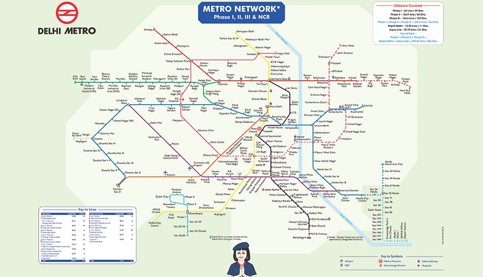
Basic attributes of planning were speed of construction for a larger size project and yet economical, as the costs involved were large. Fig 1 gives alignment of phases I, II & III. Phase IV is now in active stage of planning & construction.
Similarly, a large number of long elevated viaducts are in various phases of construction. These include 26 km long Delhi-Gurgaon Toll Raod, 10 km long Bangalore-Hosur Elevated Toll Expressway, 4 km long Barapullah Elevated Viaduct, 4 km long Badarpur Elevated Expressway etc. All these viaducts are servicing their intended purpose efficiently. In fact, it is difficult to imagine life without these metro & road viaducts.
Elevated Viaducts
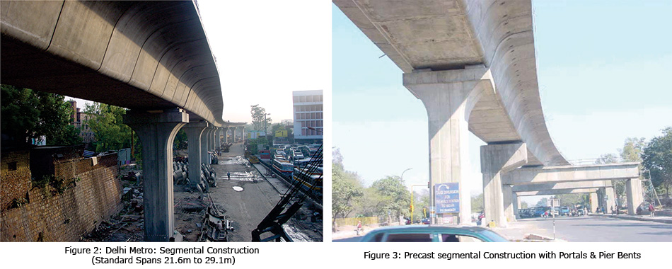
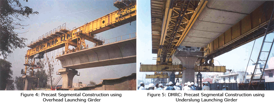
Broadly elevated viaducts have been conceptualized as Precast Segmental Box Girder which are Epoxy Jointed and Internally Prestressed (bonded prestressing), except in some stretches, where prestressed I-girder in combination with cast-in-situ RCC deck slab & diaphragm have been used, see fig 2. However, at diverging track location, either cast-in-situ voided slab superstructure or girder-slab superstructure have been used. At places where the viaduct crosses over an existing road, Portals and Pier Bents using high strength concrete have been provided, see fig 3. Launching of segments has been carried out using overhead and underslung launching girders, see fig 4 & 5. It is worth mentioning here that in the case of a Metro Viaduct, the riding quality comes from the continuity of the track, unlike a road viaduct where continuous superstructure is preferred for better riding quality. Hence, most of the metro viaduct comprises simply supported span superstructures, except at the locations of larger obligatory spans, where 3-4 span continuous superstructures have been provided for controlling depths of the superstructure and for feasibility of construction.
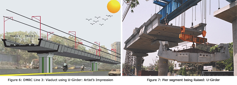
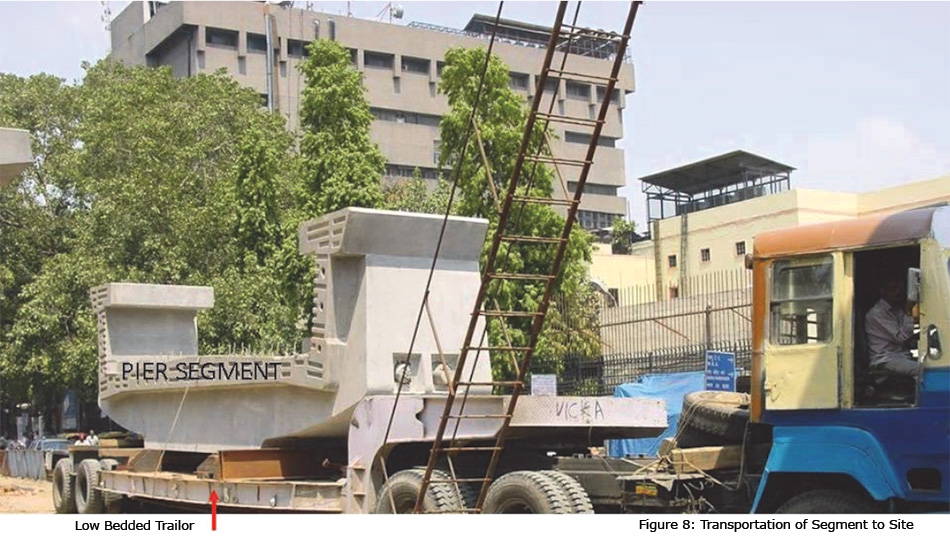
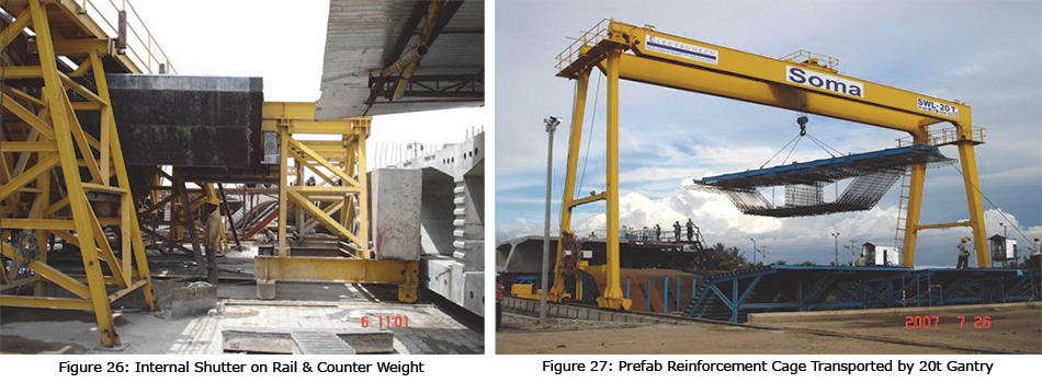
Apart from regular box girder section, C-shaped sections were also used for some stretches, see fig 6, 7 & 8. Advantage of this type of section is that the side webs work as parapet, thereby saving of material and truncated top flange acts as emergency evacuation walkway. At the same time, the rail level comes down, as the tracks are supported over the bottom slab, leading to economical designs.
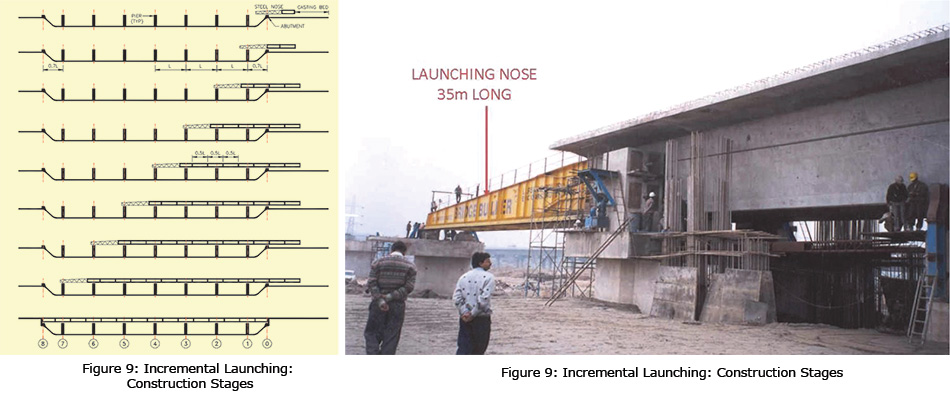
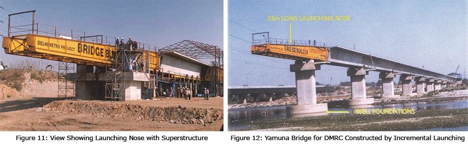
Incrementally Launched Bridge over River Yamuna
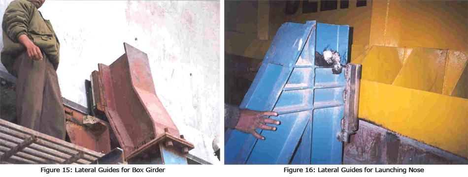
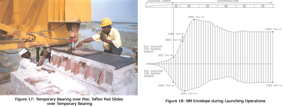
It was decided to provide an Incrementally Launched bridge over the river, so as to avoid any requirements of ground supported staging or launching girder. In an incrementally launched bridge, casting is done at one of the two banks, which gives factory quality concrete. In this case 552m long bridge comprises 12 spans of 46m each. At every typical stage, 23m long length of box girder is cast and pushed forwarded. Figs 9, 10, 11 & 12 depict the system of incrementally launched bridge. Figs 13 & 14 depict the system of pushing the superstructure using strands and multi-pull Jacks (400 T capacity each, in this case) Figs 15 & 16 indicate the side guides required for lateral alignment control of superstructure and launching nose, respectively. Fig 17 depicts the system of sag control of the launching nose.
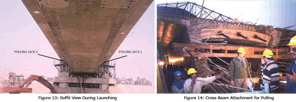
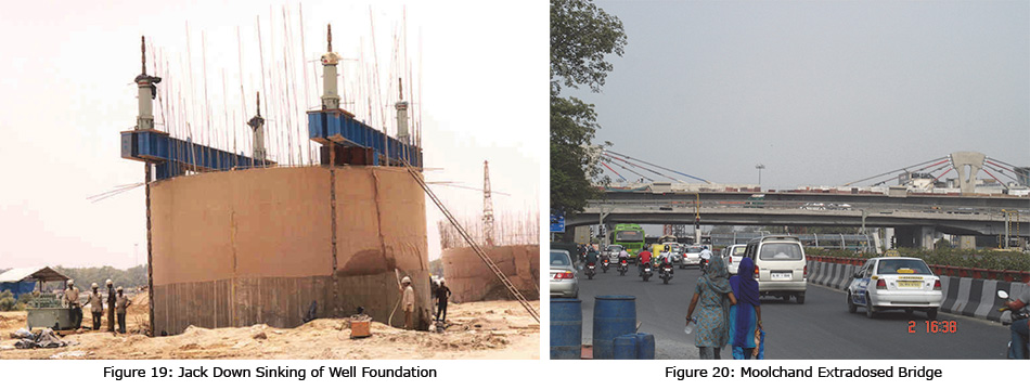
As the structure moves forward during push launching, every section of the superstructure is subject to hogging as well as sagging bending moments, see fig 18. This necessitates maintaining adequate compression (through prestressing), both at top and bottom. Hence, temporary external presetressing cables, housed in HDPE ducts, had to be provided. The well (cassion) foundations were sunk using Jack Down sinking method, to speed up the process, see fig. 19.
Extradosed Bridge
Extradosed bridge technology is comparatively a new one, that falls in the category of cable supported bridges. Extradosed bridge looks similar to cable stayed bridge but the difference is that in the former case, Pylon is much shorter, deck is usually integral with the Pylon and potential for Fatigue Effects is negligible.
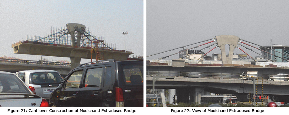
One such bridge used in Delhi Metro is Moolchand Extradosed bridge, see fig 20 to 22. The central span is 65m, parallel to an existing flyover and is located above an already constructed vehicular underpass. Pylon height is 12m, which is about half of that for a cable stayed bridge for similar span. Other advantage is of aesthetics, which is due to comparatively shorter Pylon. In the middle of a city, providing tall Pylon and the connected cables are not desirable, as they divided the continuity of the view.
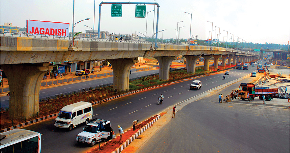
Bangalore Hosur Elevated Expressway
The project of Bangalore-Hosur Elevated Expressway provides a vital high speed link between South East Bangalore and the famous Electronic City, that houses world famous IT industry. The project comprises 10 km long elevated viaduct, a complex traffic interchange, two flyovers and several vehicular and pedestrian underpasses (VUPs and PUPs), apart from ground level roads. Owners laid emphasis on riding quality and made it mandatory for the contractor and designer to keep the spacing of expansion joints as large as 262 m. The elevated viaduct has been constructed using precast segmental superstructure, continuous over spans (29m+6×34m+29m=262m). Sharply curved interchange superstructure at Electronic City has been conceptualized as cast-in-situ RCC (Reinforced Cement Concrete) voided slab with spans ranging between 20 m and 35 m. The VUPs and PUPs have been constructed using Box Pushing method. Speed of erecting superstructure for each span of the 262m long module was about 3 ½ days. As the single box girder carried two carriageways, the speed is said to be 1.75 days per carriageway span. Main attributes to the speed of construction were the use of wireless remote controlled launching girder, matching speed of production of precast segments, produced using short bench method.
Evolution of Structural System
It was decided by the concessionaire to divide the construction of the 10 km elevated viaduct into three different contracts, to be executed by different contractors. Each contractor was to have separate precasting yard. It was necessary to ensure that the segment size and weight were in transportable range. At the same time construction speed was of a high importance for a Build Operate and Transfer (BOT) project.
An overall optimization led to the solution of providing 16 m wide twin cell box girder to carry both up & down carriageways over one superstructure see fig 23. This way, the number of precast segments could be reduced to half. Height of the superstructure is generally in the range of 8 m to 12 m. As a result the piers are not very tall. Most piers are supported over pile foundations, comprising 1.2 m dia bored cast-in-situ RCC piles, resting over rocky substrata. However, some of the foundations had to be made into open foundations resting over shallow rock.
When it comes to the flyovers and approach ramps joining the main viaduct, it was not found appropriate to provide precast segmental box girder, due to lesser number of repeats, which are generally necessary for the economics of precasting. In order to maintain a reasonably good construction speed of these structures, use of precast-prestressed girders in combination with cast-in-situ deck slab and diaphragm was found to be a suitable choice. Prestressing system of the girders was chosen to be post-tensioning instead of pretensioning. It may be noted here that although, pretensioning entails higher construction speed, it can be implemented only in the cases where the number of girders are 100 and above, due to the reasons of economy. As regards VUPs and PUPs, the available choices were use of conventional retaining walls which is slower and less traffic friendly, Diaphragm Wall which is much faster but will still cause disturbance to the traffic during construction and Box Pushing which is slower but entails practically no disturbance to the traffic during construction. Hence, looking at the traffic density on the busy road, it was decided to go for Box Pushing technique, which is much more costlier than the other alternatives. The technique requires construction of temporary concrete abutments to take reaction for the hydraulic jacks for pushing the stagewise cast segments of the RCC box to be pushed. This technique has been frequently used in India for making underpasses below the running railway lines.
The Superstructure
Superstructure of the elevated viaduct comprises 30 nos. of 262 m long continuous superstructure modules, resting over POT bearings over the respective pier caps. Analysis and design of superstructure had to account for the stages of construction. Hence, it became prudent to discuss with contractors as to the construction methodology. There were mainly two ways of constructing continuous superstructure. One was to construct simply supported spans resting over pier caps including prestressing of individual spans. Thereafter casting the stitch segment over the pier and stressing integration cables. This option would cause larger sagging bending moments during construction, usually leading to uneconomical structure. The other option was to construct 1¼ span, then ¾ & ¼ span and so on and ¾ span at the end. Thus construct the eight spans in eight stages and prestress selected top and bottom cables at each stage. This option was found to be more efficient and was chosen for the project.
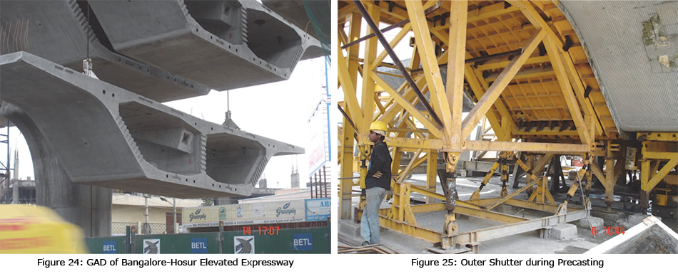
Shape of the 16 m wide box girder was chosen to be a 2 cell box in order to avoid second operation of transverse prestressing of deck slab, see fig 24. The box cross section was suitably shaped for an acceptable architectural form simultaneously giving due regard to structural behaviour. Drainage water pipe was passed through the pier diaphragm at transverse centre of the box girder, for enhanced aesthetics.
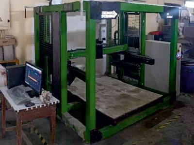
Precasting, Transportation and Erection
There are mainly two ways of precasting the segments, viz. Long Line method and Short Bench method. The former requires the constructors to replicate the span of a particular construction stage as casting bed, wherein all the segments are cast next to each other by Match Casting technique. The scheme requires more casting space, but it is simpler whereas the latter requires only two beds. The previously cast segment is shifted away and be the main bed cleared for casting of the next segment against the previously cast segment by Match Casting technique. This technique is superior and faster in nature and was employed for the said project. In this technique, the outer shutter is placed on collapsible platform for easy removal, see fig 25. The inner shuttering is made cantilevering type, which can be inserted into the outer shutter and extracted, easily, see fig 26. The bed at bottom is attached to a shaft, which can pull the bed on rails, after lowering the segment on to the moveable bed. In order to further speed up the process of precasting, the entire reinforcement cage of the box girder segment is prefabricated elsewhere in the precasting yard and lowered into the outer shutter using a crane, see fig 27. Since, the reinforcement cage is not structurally strong enough to take the handling forces, it is temporarily strengthened using structural steel sections and lifting of the reinforcement cage is spread over 3-4 locations. This way, a high speed of production of 1½ days per segment per casting bed could be achieved. A total of 3000 segments were casted.
In order to transport these segments from precasting yard to the site, specially fabricated low bedded trailers were mobilized. The transportation was restricted to night time only, in order to reduce traffic problems. Erection of segments at site was facilitated through heavy duty cranes capable of lifting over 100 t segment. In some cases, the low bedded trailor was placed directly below the launching girder for a pick up. The segments were adequately secured to the trailor bed, with the help of chains and steel members (properly bolted) to ensure control over possible toppling of the segments during turning of the trailor, carrying it.
Launching and Joining of Segments
Launching of segments is an important activity. There are broadly two ways of launching the segments. On using Underslung Launching Girder and the other using overhead Launching Girder. The former entails lesser height during construction and is comparatively slower. The latter one is faster and better method of launching. It entails hanging of segments with wire ropes using electrically controlled pulleys mounted over the Overhead Launching Girder (LG). Typically the LG is 2¼ span long. For the current project three LGs were deployed. Each one controlled using wireless remote control for easy operations. This way a speed of as high as 3.5 days of launching per span superstructure per LG could be achieved. Needless mention that each span superstructure accommodates dual carriageways, implying a speed of 1.75 days per span carriageway per LG, see fig 28.
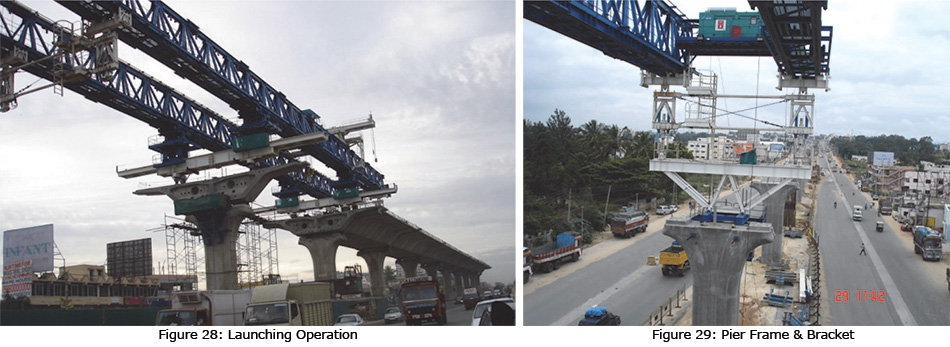
The overall operation of LG comprises the following: (i) placement of a bracket and pier frame on the forward side pier and supporting the LG on the same, see fig 29. (ii) Lifting and placing of respective pier segment over temporary hydraulic-screw locked jacks over the forward pier cap. (iii) Placement of the LG over this pier segment. The pier frame becomes redundant at this stage and can be taken to the next pier. (iv) Erect the segments of the respective ¾+¼ span.
After this operation, Epoxy Bonding Agent is applied to the segments one after the other and temporary prestressing of 0.3 MPa imported in the same sequence. Once the entire span length is applied with Epoxy Bonding Agent and temporary prestressing applied, the permanent prestressing is applied and temporary prestress demobilized. At this stage, the LG is ready to move for the next span launching.
Problems Encountered
At the time of construction of foundations, the routine pile load test could not satisfy the test criteria at a few locations. As the pile load test was carried out at discrete foundation locations, the pile caps for the rest were constructed even before the pile load tests were carried out. When the test revealed 30% - 40% less pile capacities, it was decided to augment the number of piles from 4 to 8, even where the pile caps had already been cast. Then in order to satisfy the structural strength of the piles, use of Post Installed Rebar Fasteners was made to increase length and thickness of the pile caps. Though expensive but a workable system could be found and demolition of the pile caps could be avoided.
Delhi Gurgaon Expressway
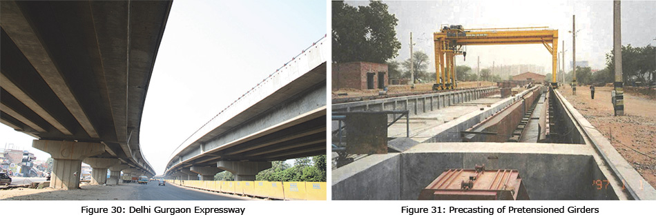
Precast Pre-tensioned girders integrated with cast-in-situ deck slabs and diaphragms were used on a large scale for the superstructure of the 2 x 4 lanes of the access-controlled expressway incorporating several grade separators aggregating 11 km of stilted structure. The requirement of precasting 1800 girders was met through a casting yard comprising 14 beds and a process of steam-curing to obtain a time cycle of upto 4 girders a day. Specially fabricated low-bedded trailors were deployed to transport the 30 m long girders (weight 60 t) to the site and a pair of Goliath cranes operating in tandem was then used for their erection. A pair of 150t tyre-mounted mobile cranes was also engaged at designated locations for the purpose. Special highlights of the designs were the “integral” sharply curved (radius 50 m) prestressed cast-in-situ box girder continuous decks for the “horse-shoe loop” connections towards the international and domestic terminals of the IGI airport of Delhi.
Evolution
Several Structural Schemes were considered for the BOT project. A detailed comparison of the following types was made in the beginning of the project in the year 2002:
- Cast in-situ/precast spine beam super- structure
- Precast segmental epoxy jointed box girder superstructure
- Precast pretensioned/post-tensioned girder superstructure
Precasting of Pretensioned Girders
Long line method of casting of pretensioned girders was adopted. A combination of well arranged precasting yard and steam curing made it possible to achieve a precasting speed of 105 girders per month. For the purpose, 14 precasting beds, 6 nos for 30m girders and 8 nos for 25m girders were provided, see fig 31. Large stroke hydraulic jacks with screw lock system, each of 500T capacity were employed, 2 for each line of girders stressing. After 12 hrs of steam curing, the girders attained strength about 80% when the prestressing could be imparted. Subsequently, they were moved to water curing and stacking beds. This way, a construction cycle of 1 girder in 3 days per precasting bed could be achieved, which is about double the speed of equivalent completely water cured precasting. Before transporting the girders, the end faces were properly roughened by 100% hacking, so as to develop effective bond with the cast-in-situ diaphragm.
Transportation and Erection
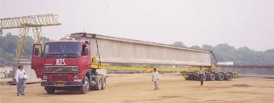
Specially fabricated low bedded trailors were employed to transport 60T weight of 30m long girders. The trailors had dual power steering for better turning, see fig 32. It was also ensured that the total height after placing of girder over the trailor was less than 5.5m, so that the same could pass below the flyovers on the way. All the transportation was done at night, in order to reduce traffic disturbance.
Erection of these girders was facilitated in two ways. In case of shorter stretches, two type mounted cranes worked in tandem and in case of longer stretches, parallel tracks were laid to move two Goliath Cranes to move with the girder in tandem.
Speedy Construction
Overall speed of construction requires matching speed of all activities, such as precasting, transporting, erection etc. In this case another critical path observed was casting of deck slab and diaphragm, which is a time consuming process. In order to surmount this difficulty, a large number of sets of formwork of deck slab & diaphragm casting were employed to speed up the work. Since, there were also other constraints of land availability etc. only a certain speed of construction was required, which is not necessarily the fastest, unlike precast segmental box girder etc.
Barapulla Nallah Elevated Road
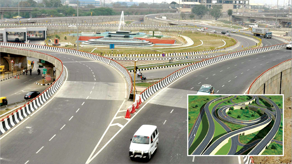
Barapulla Elevated Corridor, The Fast Track “Village to “Venue” Project was commissioned by the PWD Government of Delhi for the Commonwealth Games (CWG 2010). The elegant design of Barapulla Elevated Corridor, was envisaged as a dedicated signal-free access to transport participants from the Game Village to the Main Vennue (Jawahar Lal Nehru Stadium), see fig 33. Located along the existing Barapulla Nallah drain, the 4.5 km long viaduct consisting of 2 separate structures of 10m width each for the up and down traffic, has an important legacy value for the east-south traffic of Delhi.
The innovative design concept was geared for high speed construction (time available: 20 months) using precast prestressed segmental techniques (no. of segments 3000) for most of the alignment including obligatory spans (upto 85.0 m), employing Balanced Cantilever construction. A specially designed Segment Launcher was employed for the purpose. Standardisation was the key to cost-optimisation while decreasing the expansion joints in the deck led to increased riding comfort.
Evolution
As the project was mooted for Delhi Commonwealth Games 2010, time dead lines were fixed and they were tight pressed. Hence a structural scheme had to be found that would go unhindered. It was decided to go for precast segmental box girder spans, simply supported with deck continuity. The discrete advantage offered was that whenever foundations were delayed due underground utilities and geotechnical issues, other foundations and substructures could be taken up and substructure erected. After demounting the launching girder and mounting it at the other location, the construction could proceed. The deck continuity still maintained better riding quality.
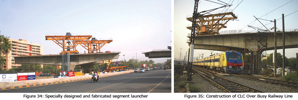
Another special consideration was required where long span special crossings had to be constructed, such as the ones over roads and over the Northern Railway tracks. For these locations 3 to 5 span continuous superstructure modules with up to 84m main span, integral with piers were devised. Integral structure not only helped in avoiding maintenance demanding bearings and expansion joints, it also reduced the requirement of large pier caps and temporary supports to stabilize the cantilevers during construction. The segmental cantilever construction was facilitated using specially designed and fabricated segment launcher, capable of lifting and moving with 100T segment, see fig 34. In order to reduce the locked in forces due to creep, shrinkage and temperature variations, that occur in integral bridges, the middle piers were made into twin piers with reduced dimension in longitudinal direction of the bridge. Shape of superstructure, specially the depth, was so chosen that for the large spans, only a few segments near the piers would have deeper and varying depth segments requiring special precasting moulds. Others could be casted using regular precasting moulds.
Precasting
Precasting of the segments was carried out using long line method and segments cured using water curing.
Transportation and Erection
Transportation of the segments was carried out using low bedded trailor, wherein the bed (bottom of segment) would be at about 1.0m height from the ground. A problem had to be solved in the case of 84m span structures, as the segment depth was too large. These trailors had to be moved below existing flyovers having 5.5 vertical clearance. The pier segment of the 84m span module had to be 4.85m, making it a total height of 1.0+4.85 = 5.85m > 5.5m. It was decided to make the pier segment cast-in-situ and the subsequent segment could be limited to 4.5m depth, hence transportable.
Launching of the standard span was carried out using overhead launching girder. Whereas, launching of segments of the cantilever construction of the large span modules was carried out using specially designed and fabricated segment launcher. This launcher had a capacity of lifting and moving with the 100T segment. The process made the operation fairly fast.
Construction of Railway Span
Added difficulties had to be surmounted while constructing 5 span module, specially 84m span over the railway tracks, see fig 35. The modules has spans 51m+84m+33m+84m+51m. Construction of 84m span over railway track was permitted only when their was no train below. Being a busy Delhi-Mumbai line, a block time of only two hours, 12 midnight to 2am on alternate days was permitted. To make this possible, feeding of the precast segments and prestressing operations was performed at every stage of cantilever construction from the non-railway track side (i.e. one end stressing). All the preparatory works, erection of segment on non-railway track side and temporary prestressing were done in the remaining time and erection, epoxy application, temporary prestressing and permanent prestessing of the railway track side segment were done during the two hours block time. This way, the construction of one of the most difficult portion could be completed within the stipulated time before Commonwealth Games.
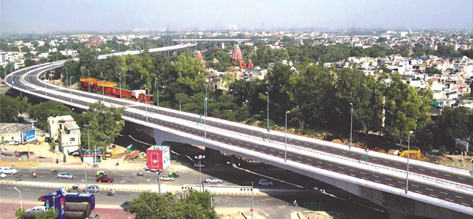
Badarpur Elevated Corridor
Badarpur Elevated Toll Corridor, New Delhi was constructed as a part of the Golden Quadrilateral under NHDP on BOT basis. This 4.4km long 2x3 lane elevated highway is located on Delhi-Agra Section of NH-2, see fig 36. It crosses 5 major intersections and has 2 toll plazas. It is characterized by spectacular geometrics, which has earned for itself the nick name of ‘jalebi chowk’. Precast prestressed concrete segmental construction (2200 nos. segments) was the predominant technique used for the spans varying from 28m to 46m and carriageway width of 11.8m. The flexibility in the design concept permitted modifications in span arrangement required during construction when unchartered utilities were encountered. Highlights of the design included minimum disturbance to existing traffic at ground level during construction and the creation of an outstanding visually arresting concrete structure. The sharp curvatures required to fit the structure to the alignment introduced complexities in segmental construction that were successfully addressed by the designer and the contractor.
The Structure
Structure of this mega project had to be so conceptualized that fast track construction was possible with least disturbance to the traffic because the project site encountered extready traffic busy roads. Also, being in urban habitat, the air pollution had to be reduced to a minimum. It is also to be noted that the entire elevated structure shape became extremely complex in geometry because land only on one side of the main road NH2 was available, due to archeological constraints on the other side, and also the requirement of NHAI that movement in every direction had to be provided for at ground level, signal free. So both ground level roads as well as elevated roads have been provided with signal free movement in all directions. As a result, the viaducts and ramps have sharp plan curvatures and complex geometry at diverging/merging road locations.
A structural form similar to Barapulla Nallah Elevated viaduct was conceptualized, but for the difference of standard span lengths which are larger and deck width which is also larger in case of Badarpur Elevated Corridor. Similar deck continuity to connect simply supported precast segmental box girder has been used. Typically 3x34m span modules resulting into expansion joints at every 102m, for improved riding comfort.
Construction
Precasting of the segments was carried out using long line method and water curing. Transportation at night using low bedded trailors and launching and erection using cranes and overhead launching girder was done. Conclusions
It is an international practice to provide long elevated viaducts for metro as well as road to effectively reduce the traffic problems. There is a marked improvement in the environmental aspects and saving of fuel, once long elevated viaducts for metro & road connectivity are commissioned.
Precast segmental box girder has been found to be the best structural solution, the world over. Success lies in making wide box girders like in the case of Bangalore-Housur elevated expressway, wherein both the carriageways are on one box girder which is a twin cell box girder. This way the precasting, transportation, erections and launching lead to an overall reduction of construction time. Before planning such projects that involve precast members in urban areas, it is extremely important to foresee the issues relating to transportaion, launching, erection, etc.
When an average high construction speed is required, solution of precast pretensioned girders with in-situ deck slab works very well because it entails much lower material consumption and reduced weight to be transported and launched. This has been appropriately done for Delhi-Gurgaon Expressway.
However, solving of specific construction related problems is inevitable. Railway span of Barapulla Nallah elevated viaduct is an interesting example, wherein despite of all odds, a carefully thought out scheme led to timely completion. U-shaped girders of Barakhamba to Dwarka line of Delhi Metro and at many other locations reduces the track level, leading to an economical structure and reduced running cost.
Published on:
02 November 2018
Published in: NBM&CW November 2018
Share:
We Value Your Comment