Design Intricacies of Precast Concrete Structures for Multi-Storied Residential Towers
Nidhi Gupta & Ahilan R. Design and Engineering team, Starworth Infrastructure & Construction Ltd., Bengaluru
The challenge with high rise construction is time, quality and cost. The uncertainty of availability of labour force makes it even more difficult to complete projects in time. In such a scenario, the construction industry is deemed to automate and modernise to cope with the demand and fulfil the growing market aspirations. Precast technology is one of the best possible solutions because with its adaptability and quality control it provides a speedy, cost-efficient and sustainable solution. Engineers and Architects also have an advantage with Precast in terms of accuracy, optimization, durability and quality control. This article discusses the design parameters of precast concrete structures for construction of multi-storied buildings.
1. Design Considerations
High rise structures are prone to lateral loads due to wind and earthquakes, so, while designing a precast concrete high-rise structure, attention should be given to the project in totality, starting from conceptual design to erection.
The seismic performance of a structure is mainly related to its lateral strength, stiffness and ductility. The lateral deflection of high-rise buildings should be controlled not only with the permissible limits by design, but also to a limit that ensures architectural finishes and partitions are not damaged.
The success of a precast system depends on connections. So, understanding of the behaviour of different connections and structure is vital in the computational models for analysis and design. As the behaviour of the structure depends on the behaviour of connections, good knowledge and understanding on connections are vital to achieve economical and practical method to connect the members with adequate strength and ductility for the structure under lateral loading.
The provisions of tie reinforcements, reinforced shear keys and dowel bars provide the required structural integrity for the precast system to avoid progressive collapse. Apart from wind loads and seismic loads, deflections that may arise due to imperfections in elements during construction should be considered. In precast construction technology, the errors in construction can be avoided with the help of proper technology and planning.
2. Design Parameters
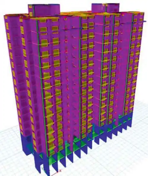 Figure 1 : ETABS Model
- Overall design of the structure for strength and serviceability requirements
- Precast element design
- Connections between precast elements
- Connection design for water-tightness
- Diaphragm action
- Design to avoid progressive collapse
- Design of architectural features/non- structural components.
Deciding the structural system for the building is foremost. The system selected depends on factors such as layout, span length, stability system etc. These systems can be broadly distinguished as portal frame systems, skeletal frame systems, wall-frame systems and cell structures. In India, for the residential towers, we mostly use the wall-frame systems. The walls are designed as load-bearing walls and thickness is decided based on the strength, serviceability and fire rating requirements. Enough RC walls are provided in both the directions to resist the lateral loads and to carry the gravity loads. Slabs are directly supported on the walls in such a case. The architectural layout is converted into the framing plan whereby the configuration of the precast elements is decided. The size of the elements depends on the layouts, preferable location of joints and the crane capacity. An analytical model is developed based on the structural framing plans. The lateral and gravity loads are defined based on relevant IS codes.
The behaviour of the structure depends on the connections and the modelling of the same shall be in accordance with the real-life scenario.
2.2 Precast Element design
Once the analytical model is completed and ensured for stability, precast elements are designed. In addition to the loads obtained from the analytical model, these elements are checked for handling stresses as well at different stages, namely demoulding, stacking, transportation and erection. The elements mainly are precast walls and slabs.
2.2.1 Precast Walls
Concrete walls have a large in-plane stiffness that provides stability against lateral loads and resists the gravity loads. The design of the precast walls should be in accordance with IS-1893 and IS-13920, depending on the seismic zone of the project. The load-bearing walls are provided with two layers of reinforcement and the detailing for every element is carried out in accordance with Codal requirements.
2.2.2 Precast slabs
In precast buildings, horizontal loads from wind or other actions are usually transmitted to the vertical elements by floors acting as plates. Floor diaphragm action means the transfer of horizontal loading across a building. The principal functions of the floor system are firstly to transfer lateral loads to the vertical walls at each floor and secondly to join individual load resisting elements into a single lateral load resisting system. There are different types of systems that can be used for precast slabs.
2.2.2.1 Semi Precast slabs
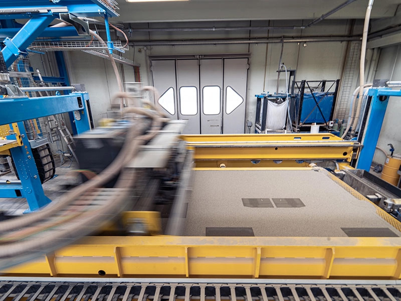
In this system, room size slabs are designed as a single unit. The slab is divided into two parts. One is the precast part that is casted at the production facility and then transported to site for erection and the other part is the cast-in-situ topping. Enough reinforcement is provided in the topping portion to ensure the diaphragm action. The precast slab also acts like the formwork for the cast-in-situ concrete and needs to be propped at fewer locations. It is also easier to route the MEP services in this case.
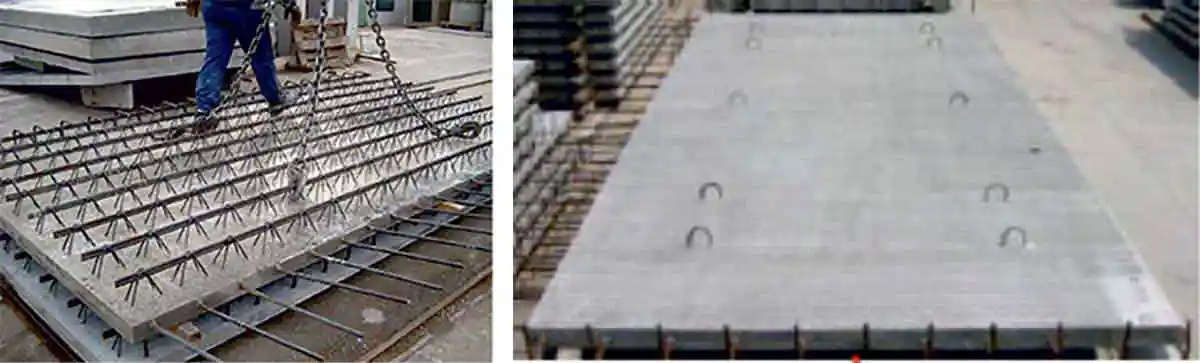 Figure 2: Types of Semi-precast slabs (Image source: Google)
2.2.2.2 Hollow core slabs
These are Precast pre-tensioned slabs and the thickness can be decided as per the span. There is an overall topping of minimum 60mm provided to ensure the diaphragm action. In case topping is not provided, the joints between the hollow core slab units should be properly reinforced to take care of the forces generated due to diaphragm action of the slab. For residential construction in India, this system is not very popular as the spans are small, and the overall thickness of these slabs is more, which reduces the clear height of the floor.
2.2.2.3 Full Precast slabs
 Figure 3: Full Precast Slabs (Image source: www.bca.org)
2.3 Connections between Precast elements
The most important aspect of precast design is the design and detailing of the precast connections. Their role is to provide a coherent and robust structure out of individual elements that are able to take up all acting forces, including indirect actions resulting from creep, shrinkage, thermal movements, fire, and so forth. Connections between precast elements is segregated in two types: Horizontal connections (at floor level) and Vertical connections (along the height of the floor).
2.3.1 Horizontal connections
In the Indian scenario, horizontal connections are mostly designed as dowel connections. These are the connections at floor level ensuring continuity between the verticals of two consecutive floors and the slab elements. As per IS codes, the Precast must emulate the behaviour of monolithic construction. This type of joint is the most widely used detail for emulative design.
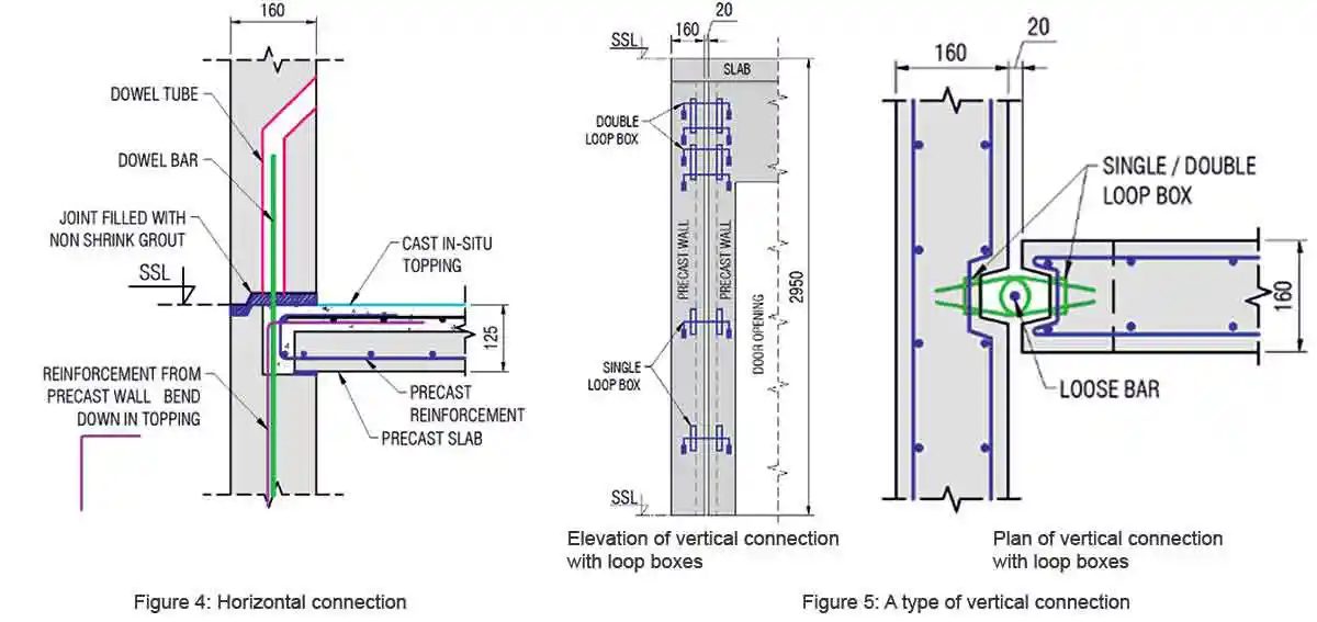
2.3.2 Vertical connections
These are the connections between two/three adjacent wall panels along the height. The vertical connectors between two different wall-panels can be various types, for example Rebars, Loop boxes etc. These connections are intended to transfer the shear forces and are designed based on the concept of shear-friction. If the shear demand for the connection is very high, shear keys can be provided to enhance the shear capacity of the connection. Different types of locations where vertical connections will be required are:
- Wall to wall connections
- Column to column connection
- Wall to frame connection
The location and the number of joints provided at the floor level plays a very important role. The crane capacity is a major determining factor in deciding the precast element configuration. Special care shall be taken while detailing every joint so that water tightness of the structure can be achieved by ensuring continuity at all critical locations. The location of the proposed cold joints is a conscious decision taken by the structural designer (simultaneously taking care of the architectural intent) and it helps to address the issue of water leakages to a large extent. A detailed method statement to treat these joints should be developed before executing the project.
2.5 Diaphragm action
The stability of the precast concrete building is provided in two ways. First, the horizontal loads due to lateral loads are transmitted to shear walls by the floor acting as a deep horizontal beam. Second, the horizontal reaction forces resulting from the floor at each floor level are transmitted to the foundations by walls. The way in which the diaphragm behaves depends on the plan geometry of the floor.
A separate analysis model should be prepared to design the slab as a diaphragm, and the slab design checked for the in-plane axial forces (compressive and tensile) produced due to the bending of the slab.
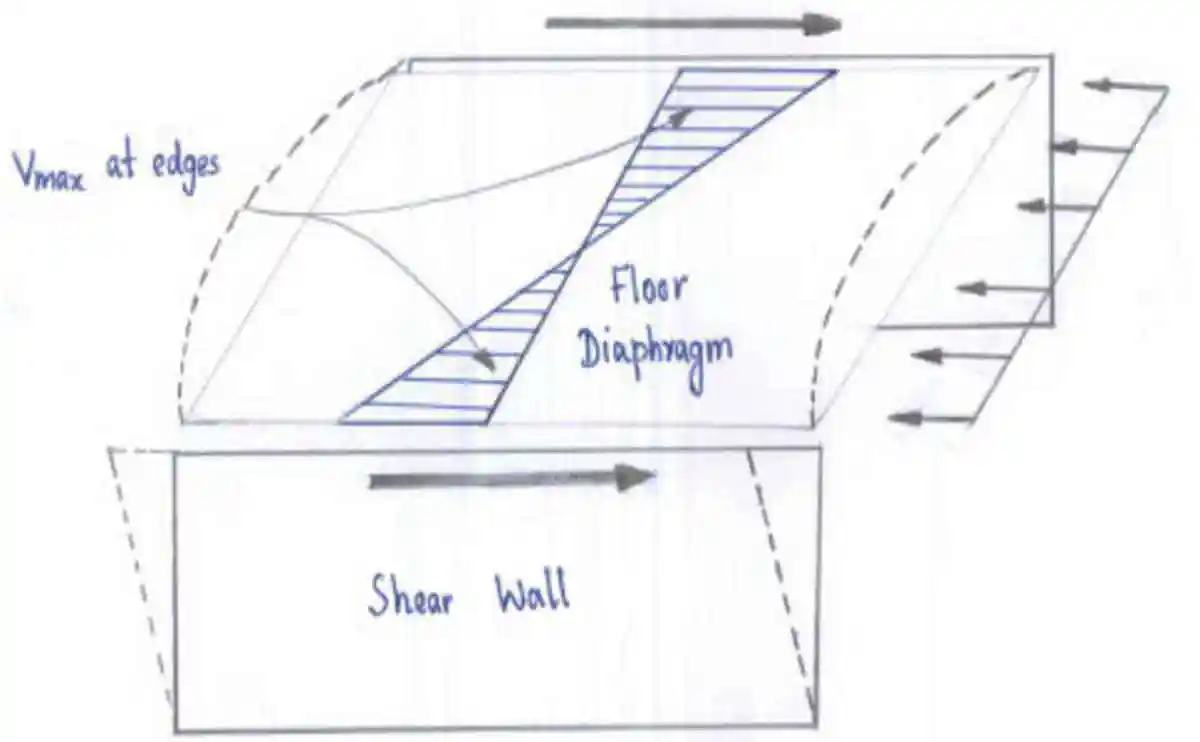 Figure 6: Diaphragm Action
2.6 Progressive collapse
Another biggest challenge in precast construction is the design of the structure to ensure stability of the building against progressive collapse in case of accidental loadings (e.g. blasts, fire, etc). Progressive collapse means a chain reaction in which a major part or the entire structure collapses due to a localized failure. In order to prevent this, proper analysis should be carried out and the key elements identified. The structure should be designed so that in case of failure of the key elements, an alternate load path is available. Enough tie reinforcements (as per codes) ensuring the continuity of the load path should be provided throughout the structure. The types of ties to be provided are detailed in IS 15916:2000 and are shown in figure 7.
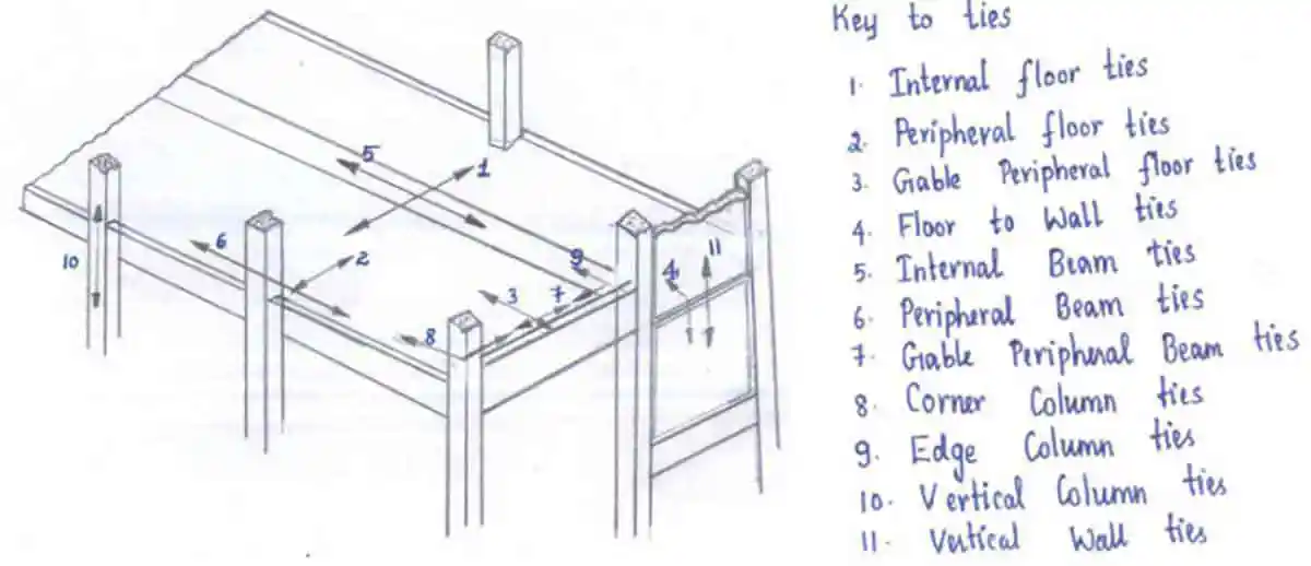 Figure 7: Types of ties
2.7 Design of non-structural components
A detailed study of all the architectural features and the non-structural components must be carried out. Proper connectivity of these elements to the load-bearing frame should be ensured. For the features where accessibility is an issue, special attention should be given in terms of safety and stability. A detailed erection sequence (along with details of the temporary supports required) should be generated. The design of the elevation elements should be checked for the varying support conditions at every stage of erection.
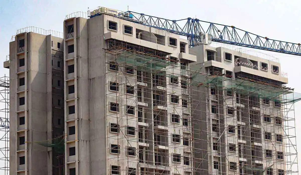
3. Case Study – Provident Park Square
Located in Bangalore, the project is executed by Starworth Infrastructure and Construction Ltd. as a Design and Build project. The project details are tabulated in table 1.
| Project Details | |
| Client | Provident Housing Ltd. |
| Design & Build | Starworth Infrastructure & Construction Ltd. |
| Location of the Project | Off Kanakapura Road, Bangalore |
| Overall Built-up area | 2.6 million sq.ft. |
| Project Size | 19 Towers |
| Structural Frames | 1 Basement+ Ground Floor +14 storey |
| Total apartments | 2085 apartments. 8 apartments per floor. |
| Storey Height | 2.95m |
| Structural system – Sub structure | Combined foundations (CIS) |
| Structural System - Super Structure | Precast large shear walls |
| Basement and Ground floor | Cast in-situ |
| 1st to Terrace floor | Precast walls, semi-precast slabs, staircases, balconies and elevation features |
| Number of elements per floor plate | 330 |
| Seismic zone | Zone II |
Few key points about the project are:
- A special profile is used for all the peripheral walls to ensure water tightness (Fig. 9)
- Both rebars and loop boxes are used for the vertical connections. The concept of structural and non-structural connections is used to optimize design (Fig. 10)
- The staircases are designed without corbel supports which look aesthetically appealing.
- Lot of architectural features such as curved columns, curved elevation bands, pergolas, and punch windows have been incorporated using Precast.
- Basement drains and compound walls are also planned with Precast.
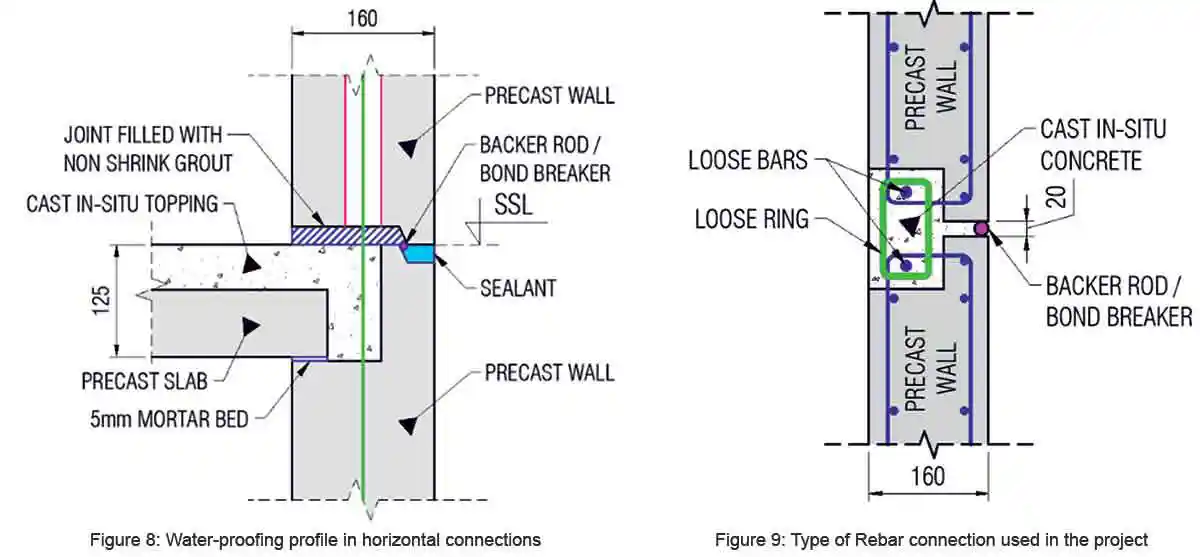
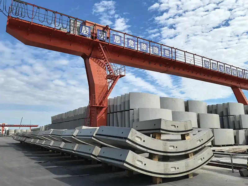
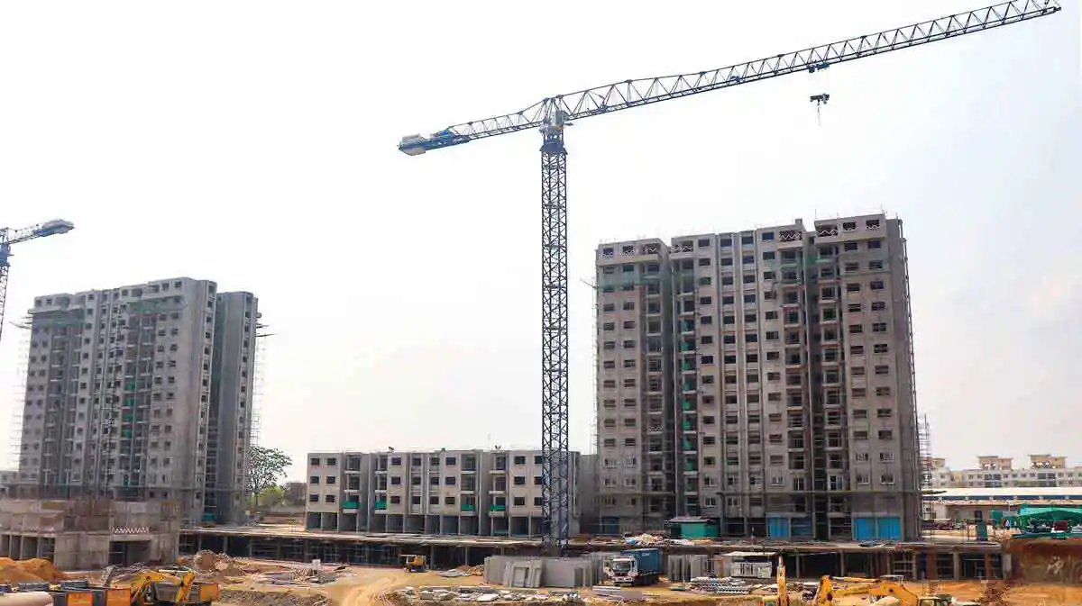 Figure 10: Provident Park Square project – Site
Conclusion
As a way forward for the Indian construction, Industrialization is the only way to achieve the quality construction in the next few decades. Precast technology will be key to this advancement and the success of any precast project depends mainly on quality of design. There must be a planned approach to the project as a whole, where structural engineers should play a vital role. In addition to parameters of building design with respect to the Codal provisions, constructability analysis is also an intrinsic part of the design stage. Constructability of every precast element should be understood in terms of crane capacity, type of production facility, type of moulds and shutters available, type and number of accessories, costing of the project, handling of elements, MEP requirements, ease of execution, etc. The aspect of water tightness, which is a major apprehension attached to Precast, should be addressed in the initial stage through proper detailing by the structural engineers.
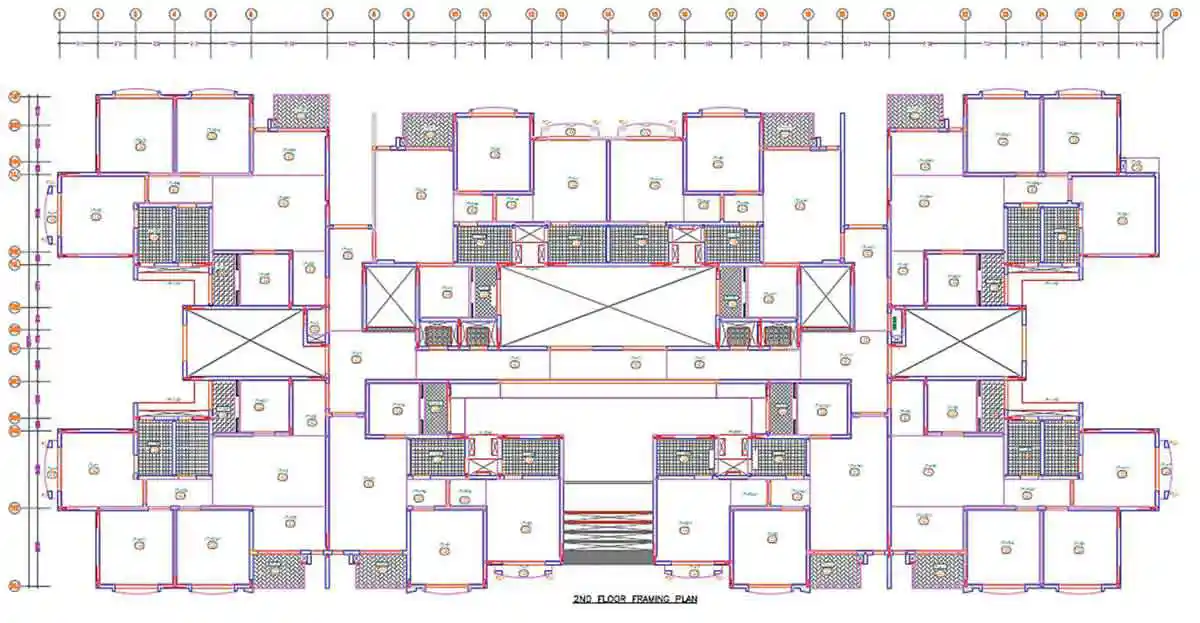 Figure 11: Framing Plan for a typical floor plate
In other words, the success or failure of residential projects depends on an understanding of the project (as a whole) by the structural engineer who should be willing to take on different roles.
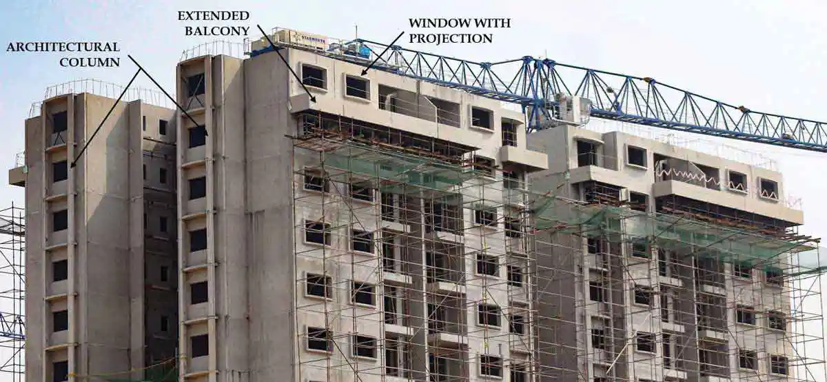 Figure 12: Architectural Features in Precast
Acknowledgements
- Puravankara Ltd. and Provident Housing Ltd.
- Mr. Raj Pillai (Managing Director – Starworth Infrastructure & Construction Ltd.)
- PCI design handbook, precast & prestressed concrete.
- FIB-Bulletin 74 - Planning and design handbook on precast building structures.
- IS: 456 - Code of Practice for Plain and Reinforced Concrete, Bureau of Indian Standards.
- IS: 1893 – 2002-Criteria for Earthquake Resistant Design of Struc¬tures, Bureau of Indian Standards.
- IS 15916 – Code of practice for Building design and erection using prefabricated concrete, Bureau of Indian Standards.
- IS: 11447 - Code of Practice for Construction with Large Panel Prefabricates, Bureau of Indian Standards.
- IS 875 – Code of practice for Design loads
- IS 1893 - Code of practice for Earthquake resistant design and construction of buildings
- National Building Code of India Volume 1 & Volume 2, Bureau of Indian Standards.
- Elliott, K.S., Precast Concrete Structures, London, 2002
Published on:
14 April 2020
Published in: NBM&CW April 2020
Share:
We Value Your Comment