Challenges in Design & Construction of 4680m Elevated Viaduct at Pilkhuwa – A Case Study
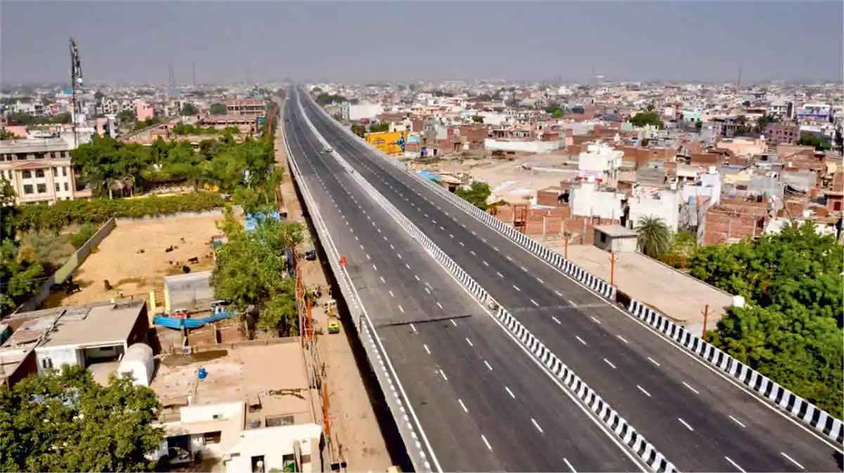 Completed View of Viaduct
The 4680m long elevated viaduct at Pilkhuwa is a part of package-3 of Delhi-Meerut Expressway Road project. It is passing through a very congested area with 24x7 heavy traffic and market on its both sides. The main challenges for completion of this project were to construct 24.65m wide deck in limited available ROW of 33m, to allow uninterrupted movement of traffic during construction and to complete the work within stipulated time frame of 910 days. To meet these requirements, apt planning was done for construction methodology, massive use of precast elements was planned to ensure maximum off-site and minimum on-site activities. As a result project was completed within available space, within time frame and with minimum hindrance to traffic
The viaduct discussed here is a part of 22.2 km long, 6-lane highway between Dasna and Hapur. It is located in a major urban corridor, which is an important link between Delhi and UP. It serves high traffic volumes throughout the day, thus cannot be closed without considerable inconvenience to road users. There was neither service road nor alternative routes, where traffic could be diverted. Hence construction of wide deck was taken up within available space with traffic plying in marketplace. Two tier road was built with support for upper deck in the median of surface level road. This concept is widely used nowadays in country. It not only eliminates the problem of land acquisition and displacement of local habitants but also reduces the overall cost of project. Wider deck was proposed over a single pier at centre so that maximum width beneath the structure is utilized. Traffic movement is allowed on two tiers, which helps in segregating local and fast- moving highway traffic.
The contract for this phase was awarded to Apco Chetak Expressway. Construction of elevated viaduct was completed in the month of April 2019. In addition to elevated viaduct the project has 15 Underpasses, one Flyover and one Major bridge. Construction of this package was commercially opened on 30th Sept 2019. The project received National Highway Award for Excellence 2018 from MoRTH for outstanding performance and innovation.
Salient features of Viaduct
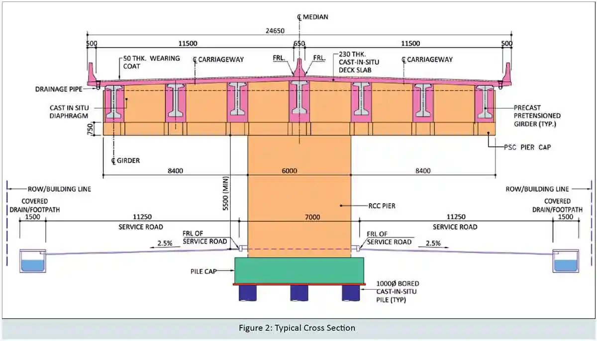
The overall deck width of viaduct is 24.65m comprising of 2x11.5m carriageway, 2x0.5m edge crash barrier, and 0.65m median. Two separate service roads of width 11.25m each was provided beneath the elevated viaduct for local traffic. 7m wide median between two service roads was used for providing piers of elevated viaduct (Fig: 2). Protective crash barriers were provided to protect pier shafts. Since elevated viaduct is 4.68km long, removable concrete crash barriers were provided in median of elevated viaduct at suitable intervals, so that in case of any emergency, traffic may be diverted from one carriageway to other by opening median. During construction, only 10m space was available on both sides of central working space (for construction) of 8.5m, from which regular traffic and construction vehicles were allowed to ply.
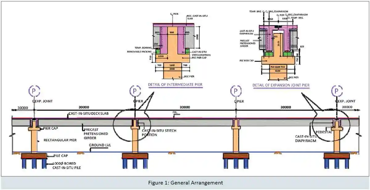
Structural system adopted for this viaduct was precast pre-tensioned I-girders with RCC cast-in-situ deck slab. 3 spans of 30m length were made continuous to have a module with 90m length. Continuity of spans was achieved by making superstructure integral with intermediate pier caps. At expansion joint ends superstructure was supported over free Pot-cum-PTFE bearings (Fig: 1). Each span had 7 pre-tensioned I-girders placed 3.6m centre to centre transversally. Girders were connected at top with 230mm thick RCC deck slab. At intermediate pier, girders were connected with 850mm thick webs of inverted T-shaped PSC pier cap and near expansion joint, girders were connected transversely with 800mm thick cast-in-situ diaphragm resting on bearings. Monolithic connection between superstructure and substructure at intermediate pier reduced the number of vulnerable items i.e. bearings and expansion joints to almost 1/3rd of what required for conventional simply supported structure. It also makes structure more safe and efficient during any seismic event.
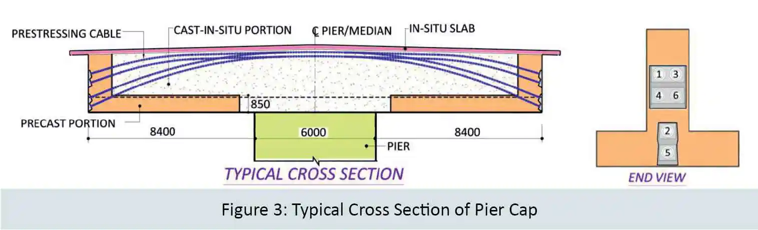
Substructure consists of inverted T-shaped part precast part cast-in-situ post- tensioned pier cap and RCC rectangular pier. Inverted T-shape pier cap was proposed with 3m wide & 0.75m thick bottom flange and 2m deep & 0.8m thick web. Casting of 22.8m long pier cap was not feasible at site, so it was divided into 3 units. Since only 8.5m space was available for construction, central 7.6m part of pier cap was made complete cast-in-situ, while 7.6m long cantilever portion on either side were made part precast and part cast-in-situ. Bottom flange and 0.75m part of web at ends (i.e. near anchorages, out of a total 7.6m length of web) were made precast while balance portion of web was cast-in-situ (Fig: 3). Cap was supported over RCC rectangular pier of width 6m in transverse direction and 1.6m in longitudinal direction.
Sub-strata observed along the length of viaduct generally comprises of layers of sand, sandy silt, fine sand, etc. There was not much variation in the layer of sand along the corridor. Liquefaction potential assessment study of the area was made considering the fact that the project is in high seismic zone (zone IV). Study reveals that liquefaction is not likely to occur at project site. 1.0m dia bored cast-in-situ pile of length varying from 24m to 29m was adopted for viaduct. Maximum load on pile was about 390t. Total 6 piles were provided at expansion joint piers and 8 piles were provided at intermediate piers. Piles were connected by RCC pile cap of depth 2.1m at top.
Design Aspects
It was not possible to cast such wide deck at site. Transportation and erection of wide segments was also very difficult due to moving traffic and restricted space availability. Therefore it was decided to use conventional pre-tensioned girders for the viaduct. Use of precast pre-tensioned girders has increased many folds in the last two decades. There are many benefits of precast pre-tensioned girders, especially in long elevated road projects.
The weight of a pre-tensioned girder is significantly less as compared to a post- tensioned girder due to reduced web thickness. But it also requires infrastructure to develop a casting yard for pre-tensioned girders, which offsets this advantage. Still, if no. of girders are ample (more than 150 nos.), it is economically viable to adopt pre-tensioned girders. Elimination of sheathing, anchorages, and post stressing grouting, etc. speed up the progress drastically. Reduction in losses of pre-stress due to friction and slip is compensated by higher creep & shrinkage loss as stressing is done at a much early age of concrete. But reduced weight of girder helps in the reduction of weight- related (i.e. seismic) forces on substructure and foundation.
The system adopted was to make pre- tensioned girders integral with PSC pier cap at intermediate support, a sophisticated analysis of entire module i.e. 90m length was done with the help of Midas software. A unit of three spans along with substructure and foundation was modelled. Pre-stressing force was applied over model and various stress limits under different load combinations were satisfied with respect to their codal provisions.
The design was done in accordance with IRC:112-2011. 15.2mm diameter Class II strands and M-50 grade concrete were adopted. The locations of strands in X-section of the girder were pre-fixed. The number of strands and their de-bonding lengths were decided by analysis and design. The number of strands in a girder varied from 33 to 35, depending on the location of girder in a module. Releasing of strands was proposed after 4 days of casting, subject to achievement of required strength of concrete.
To support pre-tensioned girders inverted T-shaped pier cap was provided. It reduced the overall height of viaduct. Pre-stressing was best solution as it restricted deflection of cantilever pier cap, make pre-casting feasible and reduced the on-site construction activities and time. PSC pier cap was easily designed with an overall depth of 2.75m. 19T15 and 12T15 cables were used in combination as per design requirement (Fig. 3). Stressing was done in three stages. In order to reduce loss due to slip, cables were stressed from one end only (Alternate cable from opposite end). After completing first stage stressing of pier cap, Pre-cast girders were placed on the bottom flange of inverted T-shaped pier cap. Second stage stressing was done after placing of girders but before casting of deck slab and last stage stressing was done after casting of deck slab. Pier cap was designed globally (with M45 grade concrete) for transverse bending, shear and locally for supporting the girders and bearings on its flange. Bottom flange was designed as corbel. For torsional design cap was divided into parts in such a way that it had maximum torsional inertia. Suitable hanging reinforcement was provided in web in addition to shear at location of girders and bearings. Small brackets were taken out from bottom flange at girder location. These brackets not only improved aesthetic of pier cap but also economised the design by reducing weight of cap and increasing pre-stress effects (P/A). These were actually planned to provide space for lifting of girders.
Construction Aspect
The structural scheme developed mainly considered maximum off-site activities and assembling it in place at the site. The pre- casting of two major elements i.e. I-girder and pier cap segment helped in reducing working width to 8.5m at road centre.
4 rigs were deployed for casting of 1148 numbers of the bored cast-in-situ piles. With each rig maximum 2 piles were completed in one day, however average rate of piling was 6 piles per day with 4 rigs. It took almost 6.5 months to complete the piling work. The casting of 157 numbers of pile cap and pier shaft was done in series.
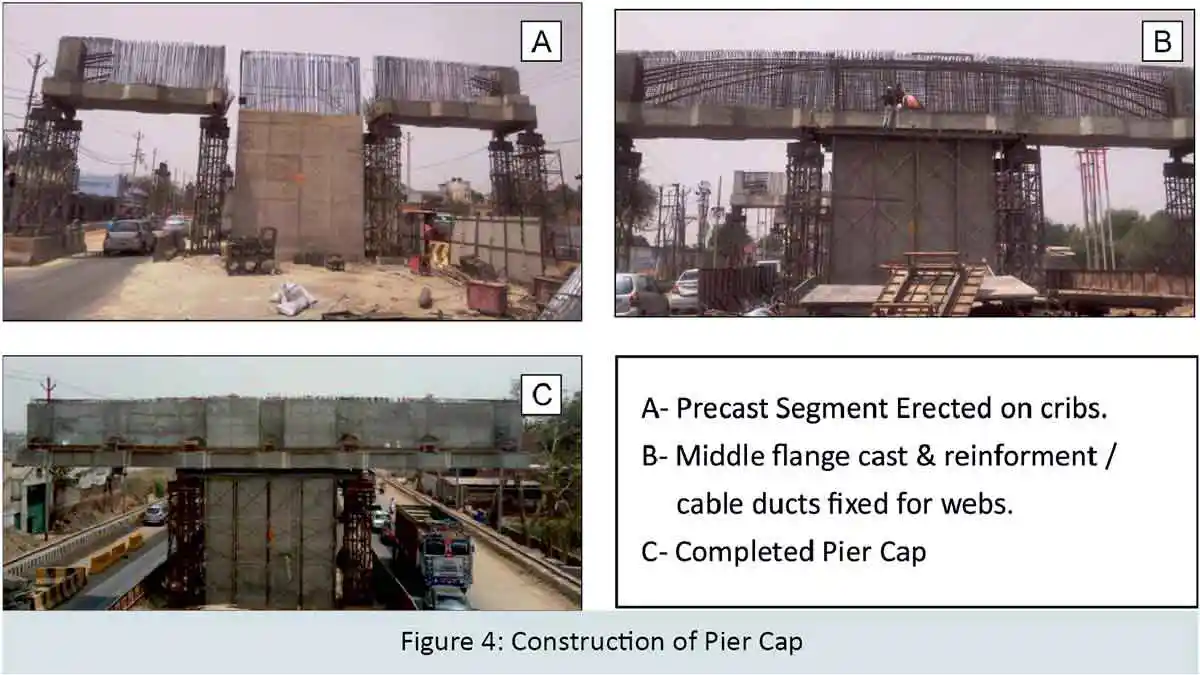
For casting of pier cap precast segments, no separate casting yard was developed, but the space between two piers on every alternate span (i.e. 30m length and 8.5m construction width) was used. It eliminated the cost involved in the transportation of segments and also prohibited the impediment to moving traffic. The alternate span space between piers was used for other miscellaneous construction activities. A total 4 segments (i.e. 2 pier caps) were cast in one span. Erection of segment was done with the help of a separate gantry (in addition to gantry used for girder erection). Precast bottom flanges of inverted T-shaped pier cap were erected & supported on temporary steel cribs resting on ground, one near median and another at edge of the cap. After a few minutes of traffic block (during lifting and placing of precast unit over cribs), restricted traffic was allowed under this precast unit of pier cap. Already erected flange of inverted T was used as a construction platform for fixing of reinforcement, supporting shuttering and casting of cast-in-situ portions of pier cap.
Once precast units were placed in position, central part of pier cap over pier and portion of web on precast part were cast (Fig: 4). When in-situ portion gained desired strength, cap was stressed transversely and cribs were released. For pre-stressing of pier cap, cantilever hanging platforms were used on either end & no support from ground was taken to allow moving traffic. Average rate of erection of pier cap was 2 caps per day. It took at least 14 days after erection of segments to stress cap with first stage cables.
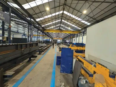
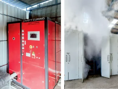
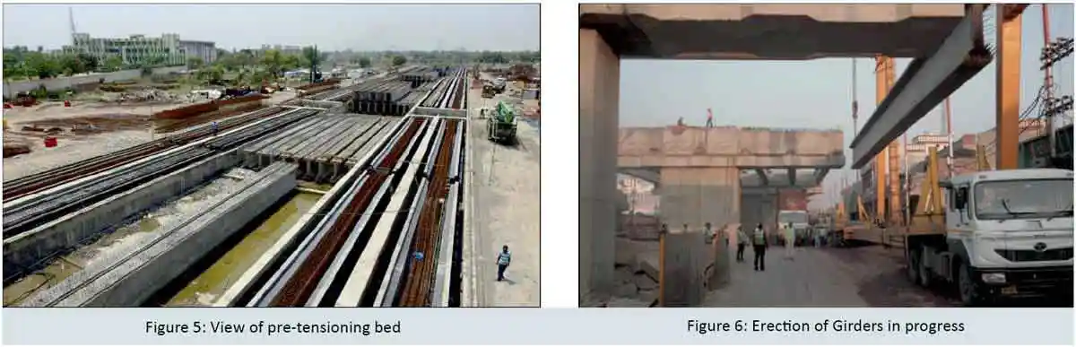
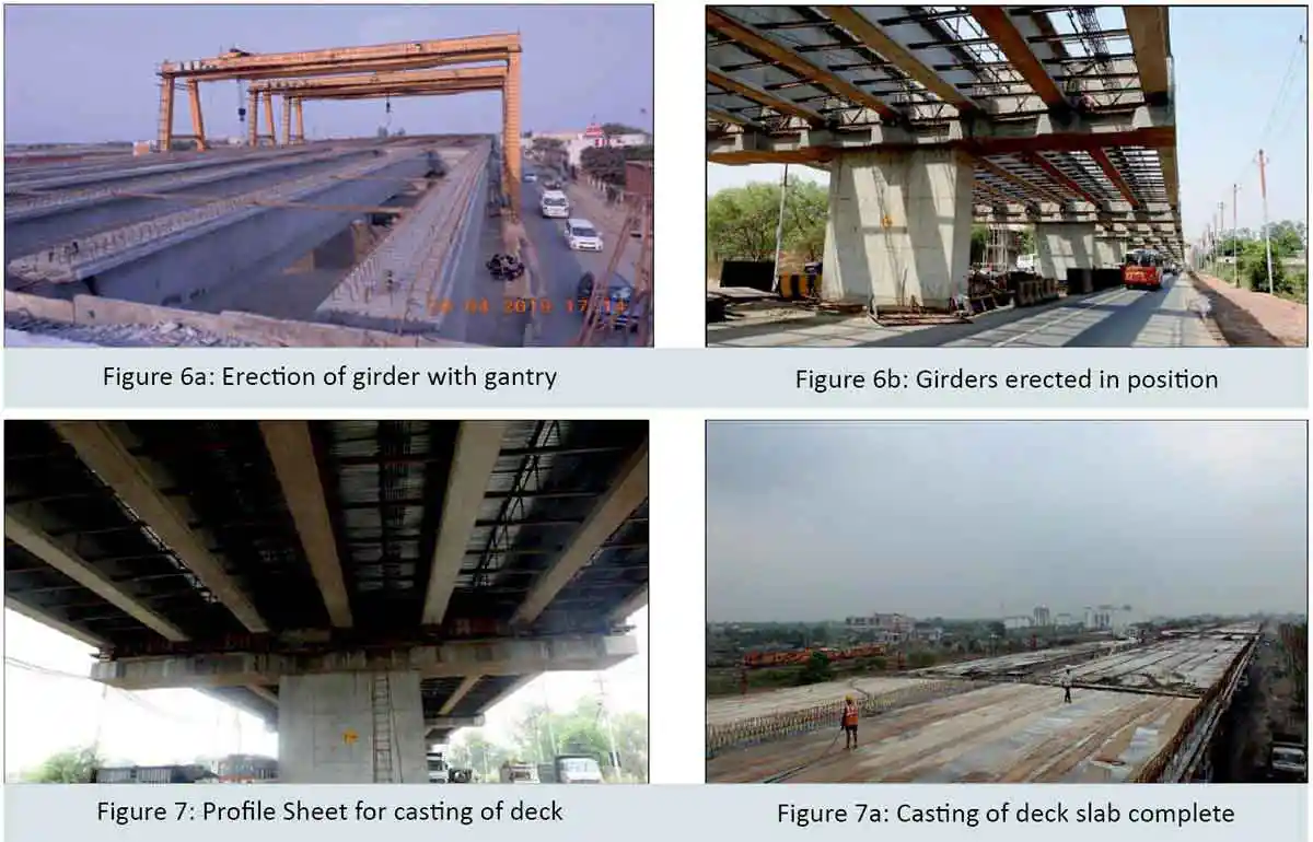
There were total 1107 numbers of precast girders (for entire project), for which 12000sqm “precast casting yard” was prepared with 12 beds & 3 girder casting facility on one bed (Fig: 5). To reduce time cycle of girder casting from 10 days to 7 days, early setting admixture were used and steam curing was adopted. 180 girders were produced in a month. Yard was having a staking capacity of 220 nos. of precast girders and construction activities were planned accordingly. A steel cutting bending and binding automatic yard of size 50m x 18m was commissioned to accelerate the progress of project. Launching of such a huge number of precast girders was a major task and was done with the help of two gantries instead of crane. Tracks for gantry were placed 30m centre to centre near outer edge of ROW. Use of gantry reduced the time involved in erection of girders substantially. Practically it took only 15 to 20 minutes to erect a girder after lifting it from trailer, thereby reducing the stoppage time for traffic drastically (Fig: 6, 6a, 6b). With gantry maximum of 14 girders were erected in a day, however average erection of girders was 4 numbers per day. At intermediate pier cap, dowels from cap were projecting out for its integral connection with precast girder. Bars from pier cap and I- girder were so planned that they do not hinder with each other during lowering of girder at its position. Space over cap available for casting of stitch portion between girders and web of cap was 0.65m only and all activities were done on such small working area with running traffic below. A complete mock-up of the entire system was done on ground before starting actual work at the site.
For casting of deck slab, sacrificial profile sheet (Fig: 7, 7a) was used in order to save time. However, for cantilever portion of deck slab, staging & shuttering was fixed from already erected girders. On an average, it took 9 days to complete one deck slab.
Innovative design concept of making pre-tensioned girder monolithic with webs of inverted T shaped PSC pier cap, well planned construction methodology, optimised use of machinery and close coordination between Designer, Contractor, Independent Engineer and Client resulted in successfully completion of the project within stipulated time frame.
Conclusion
Design and construction scheme adopted here was such that it ensured safety during construction and caused minimum hindrances to moving traffic.
Reduction in use of vulnerable elements causing trouble in procurement, requiring regular maintenance and maximum use of off-site activities not only helped in improving quality of construction but also reduced the construction period.
Present proposal of making superstructure monolithic at intermediate piers made it safer and more efficient during a seismic event.
Right coordination between Designer, Contractor, Client, Independent Engineer & optimized use of machinery and manpower resulted in the timely and successful completion of the project.
Credits
- Client: National Highway Authority of India (NHAI)
- SPV (Concessionaire): APCO-CHETAK
- EPC Contractor: Chetak Enterprises Ltd.
- Design Consultant: B&S Engineering Consultants Pvt. Ltd.
- Independent Engineer: Lea Associate South Asia Pvt. Ltd.
Published on:
17 June 2020
Published in: NBM&CW June 2020
Share:
We Value Your Comment