Advantages of Precast Concrete Technology in Metro Project (Line-06 Mumbai Metro)
The Delhi Metro Rail Corporation (DMRC) has completely revolutionized the mass transportation scenario in India. It has introduced a world-class Mass Rapid Transport System (MRTS) which is comfortable, air conditioned, eco-friendly, swanky, and modern.
Considering the success record of well-planned execution of Metro Projects by DMRC in Delhi-NCR and other cities, Metropolitan Region Development Authority (MMRDA) entrusted DMRC for construction of the 15.31 km long Line-06 elevated corridor along the median of Jogeshwari-Vikhroli Link Road (JVLR) and its depot proposed at Kanjur Marg. This Metro Line is expected to reduce the traffic on highly congested JVLR road, which is an important East-West connectivity crossing North-South arterial roads of suburbs i.e Eastern express highway, LBS Marg, Western Express highway, S.V. Road and Link Road. A Detailed Project Report (DPR) of Mumbai Metro Line 6 was prepared by DMRC for the MMRDA.
Mumbai presents a number of challenges in the design, planning and execution of metro projects due to limited space, existing utilities, and congested roads. Geographically, difficulties in setting alignment, space constraints, and short completion time remain the main deciding factors to complete a Metro Project. DMRC meticulously planned the project which in turn helps in execution of the project as per the highest standard of safety set by the industry and as per the scheduled time. Paramount importance was given to the aesthetics of civil structures, aspect of future maintenance, minimal inconvenience and danger to public life and property.
Prudent planning has allowed a diversion from traditional construction methods that is cast-in-situ, specifically in superstructures to precast technology. The innovative design concepts adopted for the project allowed to cast more than half the volume of civil structures in the casting yard as a precast unit, that is, the pier arms, girders (U, I, L,T, PI, Box) etc.
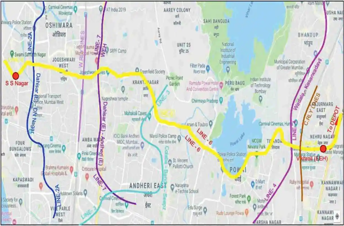 Figure 1: (Line-6 Mumbai Metro Map including intersection with other Metro Lines)
Alignment
The Line-06 Mumbai Metro of 15.31km runs from Swami Samarth Nagar to Vikhroli (EEH) in which a major portion of the alignment is along the median of the JVLR road which connects the Western and Eastern Suburbs of Mumbai. There are a total 13 stations in Line-06 and interchange with other metro lines as depicted in Fig-1. 2.58 km of combined structure i.e. Flyover + Viaduct is also part of this project. Road flyover is at first level and Metro Viaduct is at second level. It will be a seamless connection between Andheri (Infinity Mall) and Mahakali Caves (JVLR).
Alignment of metro Line-6 passes through dense residential areas (Lokhandwala complex, Adarsh Nagar, Jogeshwari, JVLR, Mahakali Caves, Rambaug, Hiranandani, etc), a biodiversity lake at Powai, IIT Powai, etc. Geographical condition of the line is such that elevation of metro track level requires horizontal curves up to radius 125m at 12-30-meter heights (approx) above the road level. Construction of this elevated metro corridor at such a height, in sharp curves (Total 53 curves out of which 17 curves are sharper than 300m radius) and steep gradients over the congested JVLR without disturbing the running traffic was a huge challenge for DMRC. To meet these challenges, viaduct and station elements were designed and planned as follows:

Metro Viaduct: Standard span of 25m with precast twin U-girders (Fig-5) on single pier with pile/open foundations and flatter and Segmental Box Girder on single pier with pile/open foundations and I-Girders at critical locations as well as for sharper curves and location of Points & Crossings.
Combined Structure: Standard span of 20m with precast twin U-girders for the Metro and precast T-girders for flyover has been provided on single piers and pile/ open foundations. I-girders at critical locations as well as for sharper curves and location of Points & Crossings.
Metro Station: Combination of standard span of 9.6 m and 17m with precast twin U- girders at rail level, T & L or PI girders at platform level, T & L girders at concourse level, one single piece concourse pier arm on single pier with pile / open foundations.
Constraints for Cast in-situ in this project
While planning the methodology for execution of metro Line-6 civil work, option of cast in-situ and precast elements were explored as per their ease of constructability as briefed below:
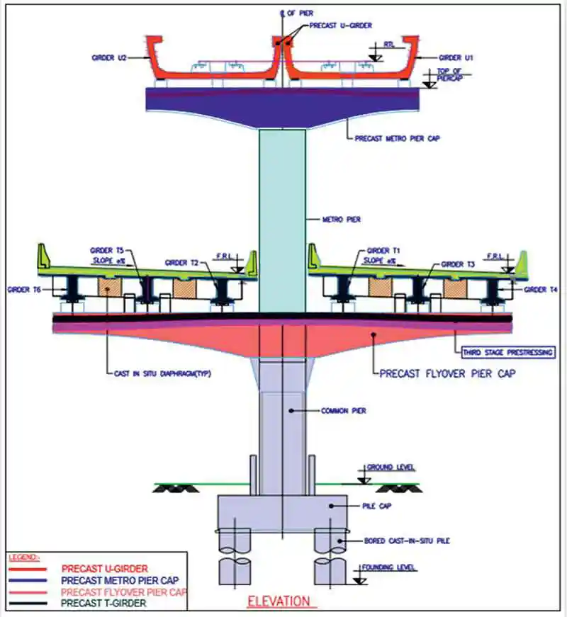 Figure 6: Typical Cross Section of Double Decker Pier showing Pre Cast Elements
The available space allocated for the metro work is 9m only, whereas the combined structure (flyover + viaduct) is 20m wide. This needs the necessary supporting temporary structures for casting in case of in situ. Providing the temporary structures for the same width in the middle of busy roads will make 3-lane roads into 1-lane and even need complete closure of the roads at critical locations. Also, the alignment runs parallel to the existing flyovers at few critical locations, making it difficult to opt for cast in situ due to less road width availability (approx 5m). Requirement of temporary structures for casting of Flyover Pier cap, Metro Pier cap and superstructure elements of both Flyover and Metro shall be increased drastically.
Therefore, it has been decided to take up construction up to bottom of pier cap by cast-in-situ method where work can be done within the allotted working space of 9m and for outside the working space precast elements for construction of superstructure above pier arms of Flyover and Metro at casting yard for timely completion of the project.
Various Elements of Combined Structure (Flyover + Metro Viaduct): The Double Decker pier has been conceptualized as a cantilever structure with common pier for both Flyover and Metro. Also, the common Pier width is 1.8m which occupies the same road width as the normal Metro Pier. A Double Decker pier casted and ready for launching of girders is shown in Fig-2.
Flyover Level: Considering the facts mentioned above under “Constraints under Cast In situ Project”, one single piece of Flyover precast prestressed pier cap of width 17.8m is designed to rest on common pier (Fig 4). Precast prestressed T-Girders of length 20m have been designed and introduced in longitudinal direction. At the joint of flanges, 300m wide in situ stitch has been provided for transverse continuity of slab.
Metro Level: One single piece of precast prestressed Metro Pier cap of width 10.56m shall rest on Metro pier (Fig 3). Both the Flyover and Metro pier caps have a central prismatic hollow section for in situ stitch concrete and for integration with Common Pier and Metro Pier.
Fig-2: Casted Double Decker pier, Fig-3: Precast Metro pier cap at casting yard
Fig 4: Flyover Pier cap ready for concreting at casting yard, Fig-5: Erection of U-Girder at site. A typical Cross Section of Double Decker Pier showing Precast Elements Fig -6, respectively.
Construction Sequence of Double Decker (Flyover + Metro Viaduct) Pier
In general, the rail level shall be kept at 11m above ground level but as flyover also runs beneath the viaduct, there will be two levels i.e Road flyover at first level, and Metro viaduct at second level which is at 19m (approx) high from ground level.
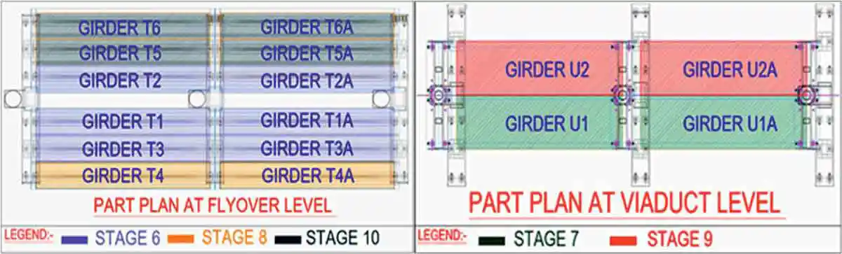 Figure 7 & 8: Typical Plan View of Double Decker Span representing Different Stages of construction sequence
- Stage-1: Casting of Pile, Pile Cap and Common Pier up to bottom of flyover pier cap.
- Stage-2: Casting of Metro Pier upto bottom of Metro Viaduct Pier cap.
- Stage-3: Erection of Precast Flyover Pier cap (with first Stage prestressing completed at Casting yard) over staging from pile cap and stitching the centre hollow portion with non shrink grout.
- Stage-4: Erection of Precast Metro Pier cap over the Metro pier using temporary collars, providing reinforcement and prestressing ducts in centre hollow portion and stitch concreting of centre hollow portion with non-shrink grout
- Stage-5: Execution of second Stage prestressing of flyover pier cap and Metro pier cap as per detailed drawing after 35MPA cube strength, of stitch.
- Stage-6: Erection of precast pre-tensioned T Girders T1, T2 and T3 (in same order) of one span and T1A, T2A and T3A (in same order) of adjacent span (Girder shall be temporarily secured in position).
- Stage-7: Erection of Precast pre-tensioned U-Girder U1 of one Span and U1A of adjacent Span.
- Stage-8: Erection of Precast pre-tensioned T-Girder T4 of one span and T4A of adjacent span (Girders shall be temporary secured in position).
- Stage-9: Erection of Precast pre-tensioned U-Girder U2 of one Span and U2A of adjacent Span.
- Stage-10: Erection of precast pre-tensioned T-Girders T5 and T6 of one span and T5A and T6A of adjacent span (Girders shall be temporarily secured in position).
- Stage-11: Execution of second Stage prestressing of metro pier cap as per detailed drawing.
- Stage-12: Casting of diaphragm at bearing location for the T-girder spans. (This can be commenced after Stage 10 or whenever 3-adjacent ‘T’ girders are erected).
- Stage-13: Casting of deck slab and continuity slab at flyover level for the T-girder spans.
- Stage-14: Execution of third stage pre-stressing of flyover pier cap as per detailed drawing.
The 2.58 km of combined structure (Flyover + Viaduct), which is part of this project, runs under Adarsh Nagar. In general, the rail level shall be kept at 13m above ground level but as flyover also runs beneath the station, there will be three levels i.e road flyover at first level, concourse level at second level and Metro platform at third level which is at 25m high from ground level. Execution of such a high-rise station building is a big challenge to DMRC due to the space constraint, heavy traffic etc. In order to tackle this issue, after considering all the site constraints, once again, DMRC came up with an innovative station building design with three levels on a single pier and foundation.
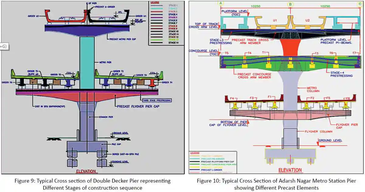
All precast elements at Flyover and Metro rail are the same as mentioned under the heading ‘Various Elements of Combined Structure (Flyover + Metro Viaduct)’. Also, at concourse level, one single concourse pier arm, precast prestressed T & L Girders have been designed and introduced as shown in Fig-10.
Construction Sequence of Three Level Adarsh Nagar Metro Station
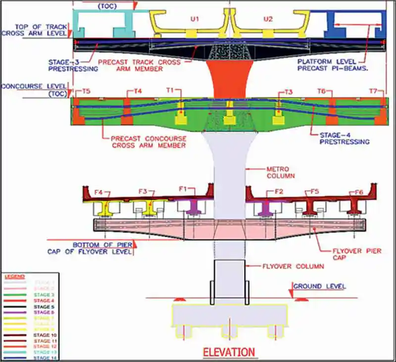 Figure 11: Typical cross section of Adarsh Nagar Metro Station three levels representing different Stages of construction sequence
- Stage 1: Casting of piles, pile cap and flyover column up to the bottom of flyover pier cap. Casting of station column up to the bottom of concourse precast cross arm. Casting of pier protection for which dowels have already left from the pile cap.
- Stage 2: Erection of precast flyover pier caps (with first Stage pre-stressing completed at casting yard) over staging from pile cap in single piece and provide reinforcement & ducts in central hollow portion. Stitch concreting of centre portion of flyover column with non-shrink concrete/grout & casting of pedestals. Arrangement of staging for concourse level cross beam from flyover pier cap.
- Stage 3: Erection of precast concourse level cross arm over staging from flyover pier cap in single piece (with Stage-1 pre-stressing at casting yard) as per detailed drawing (concourse level cross arm). Providing reinforcement & duct in the central hollow portion. Stitch concreting of centre portion of column with non-shrink concrete/grout.
- Stage 4: Casting of station column up-to bottom of track cross arm. Arrangement of staging for track cross arm from concourse level cross arm.
- Stage 5: Erection of precast track level cross arm (with Stage-1 pre-stressing at casting yard) over staging from concourse cross arm in single piece. Providing reinforcement & duct in center portion. Stitch concreting of center portion of column with non-shrink concrete/grout. Stage-2 pre-stressing as per detailed drawing (track level cross arm) shall be done. Removal of staging. Second Stage pre-stressing of the flyover pier cap as per detailed drawing shall be done after concrete attains a strength of 35 mpa.
- Stage 6: Erection of pre-cast pre-tensioned T-girders F1 & F2 to be placed respectively of one span and F1A & F2A to be placed respectively on another span at flyover level. Removal of staging.
- Stage 7: Erection of precast longitudinal RCC T-beams T1, T2, T3 at centre respectively of one span and T1A, T2A, T3A at centre respectively of another span at concourse level.
- Stage 8: Erection of U-girder U1, U2 respectively of one span and U3, U4 respectively of another span.
- Stage 9: Erection of precast pre-tensioned T-girders F3 & F4 to be placed respectively of one span and F3A & F4A to be placed respectively on another span at flyover level.
- Stage 10: Erection precast pre-tensioned T-girders F5 & F6 to be placed respectively of one span and F5A & F6A to be placed respectively on another span at flyover level. Stitch concreting of all T-girders & diaphragm shall be done at flyover level. Casting of deck slab & continuous slab at flyover level over T-girders.
- Stage 11: Erection of precast longitudinal RCC T & I-beams T4, T5 respectively of one span and T4A, T5A respectively of another span at concourse level.
- Stage 12: Erection of precast longitudinal RCC T & L-beams T6, T7 respectively of one span and T6A, T7A of another span at concourse level. Stitching of all T & L-beams shall be done. Stage-3 pre-stressing as per detailed drawing (concourse level cross arm) shall be done after placing T & L-beams & stitch.
- Stage 13: Erection/Casting of platform beams T & L-Beams or pi to left of one span.
- Stage 14 (Final Stage): Erection/casting of platform beams T & L beam or pi to right of another span. Placing of SIDL to be done at concourse & platform level. Stage-4 pre-stressing as per detailed drawing (concourse level cross arm) shall be done after placing SIDL at concourse level. Stage-3 pre-stressing as per detailed drawing (track level cross arm) shall be done after placing platform level beams.
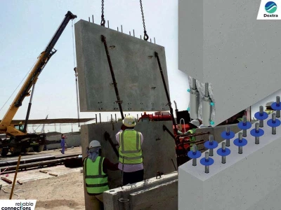
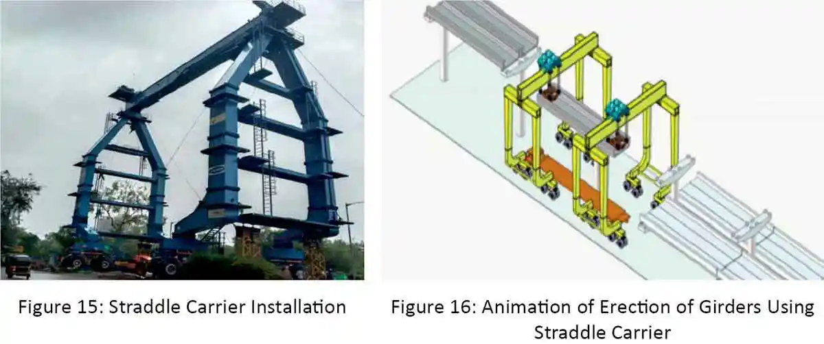
However, the success of precast technology is highly dependent on the ease of transportation and erection of the girders and station elements at the designated site location. Normally, precast elements are being erected by using cranes (Fig-5). Metro Line-6 is the first Metro project in India to use an alternate approach for the erection of precast elements. This alternative method will use a “straddle carrier”. A typical setup of the “straddle carrier” is shown in Fig- 14 and 15. It helps in easy manoeuvring and effective utilisation of time during the minimal traffic block period available in the congested areas of heavy infra work.
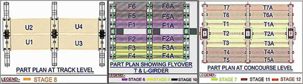 Figure 12,13 & 14: Typical Plan views of Adarsh Nagar Metro Station three levels representing different Stages of construction sequence
Currently, straddle carrier has been designed to meet the requirements of working in congested areas and erection of precast structures up to a height of 20 m and also has the capability to lift the precast members comfortably within its available width of 24 m. Each straddle carrier has a maximum safe working load up to 155MT. Due to the synchronous operation of two straddle carriers (Fig-15), this method offers high accuracy and efficiency in operation compared to use of lifting cranes in single or multi-crane lifts, which generally require additional resources of trailer for mobilisation of the counter-weights of crane and additional time in roadblock for the setting up of mobile cranes.
Conclusion
The methodology and standardization of manufacture, handling, transportation, and erection of precast elements are the major points of review and contemplation during the planning stages of the project. Approximately 60 percent of the overall construction concrete will be precast in the casting yard concurrently with the foundation work at site, thereby slashing the construction time by approximately 50 percent as compared to the conventional cast-in situ process.
Precast construction enabled us to get a better-quality control by casting in a factory-like set-up of a casting yard. Cast-in situ construction of heavy structures like U-girders, pier cross arms and other station elements would have required extensive labour and temporary structures for support from the ground and about 20m wide construction space on narrow and busy roads. The precast construction method reduced the working space to just half of it and that too at available spaces in any other location. Such gains were essentially required for the proposed metro alignment which is characterized by sharp curvatures in crowded areas of the city.
DMRC is again on the right track to achieve the assigned target for construction of Mumbai Metro Line-6 by adopting precast construction technology even after facing all the difficult situations.
Acknowledgements
- MMRDA
- DPR /Line-6
Published on:
04 February 2021
Published in: NBM&CW February 2021
Share:
We Value Your Comment