Design and Construction of Parking Structures
Introduction
Parking structures have become important elements in modern urban and suburban developments. If the land is cheap and plentiful in the area where parking is needed, then surface parking is provided. However, if the land is scarce and expensive, as is the case in most towns and cities, then a multi-story parking structure will likely solve the parking issues. Parking needs differ from one type of development to the next and therefore virtually each parking structure needs to be designed for the type, number and nature of the visits it will serve. However, providing a parking structure is an expensive proposition. While most parking structures accommodate less than 1,000 vehicles, there are some that can provide over 10,000 parking stalls.Parking structures are large in plan-view compared to most enclosed structures. They are open to the elements and experience temperature variations, go through wet and dry cycles, and in the northern climate go through extreme temperatures between summer and winter. A parking structure blends attributes of a bridge and a building. If it is designed as a bridge, it would not be competitive in the marketplace, and if it is designed as a typical building, it may deteriorate within a few years. Though a parking structure has much in common with other buildings, it has unique attributes that need to be considered in design. The following factors significantly influence its design, construction or performance:
- Special framing features
- Unique loads and serviceability
- Ventilation
- Volume changes (elastic shortening, creep, shrinkage and temperature changes)
- Restraint and concrete cracking drainage
- Drainage
- Joints and joint seals
- Durability considerations
- Pedestrian and motorist safety features
- Lighting and Way - finding
Special Framing Features
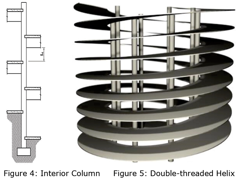
A parking facility needs to have a vehicular circulation system at each level and commonly access from one level or tier to the next, necessitating sloping ramps and helices. The parking circulation system can be classified into several basic arrangements. Figures 1 through 3 show examples of sloping or split floors. The selection of a circulation system is a complex design problem as it depends upon several factors. The sloping and split ramps impact column configuration. Figure 4 shows an interior column elevation in the sloping or split-level ramps. In facilities where all bays need to be flat, speed ramps or helices are typically provided for ingress and egress of the vehicles. For illustration, a double-threaded helix is shown in Figures 5 and 6.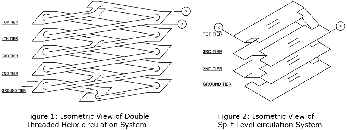
The structural framing systems that span the driving and parking stalls are called long-span systems and are popular. Such systems use members spanning from 16.7 to 19.8 m (55 to 65 ft.). In 1970’s, the long-span systems gained popularity because of efficient use of concrete and benefits of having clear space within. Today, post-tensioned and precast concrete systems dominate the market. The steel parking structures and hybrid structures with concrete floors and steel framing are also used. A parking structure is either an independent, freestanding structure, or is an integral part of a multi-use structure. This paper discusses the former type and presents a brief survey the state-of-the-art of the design and construction of double-tee precast-prestressed and post-tensioned concrete parking structures in the United States. However, the design principles discussed herein are applicable to the mixed-use and underground parking facilities. Post-tensioned concrete systems are more common in India, however, in the past few years long-span precast systems have also started becoming available.
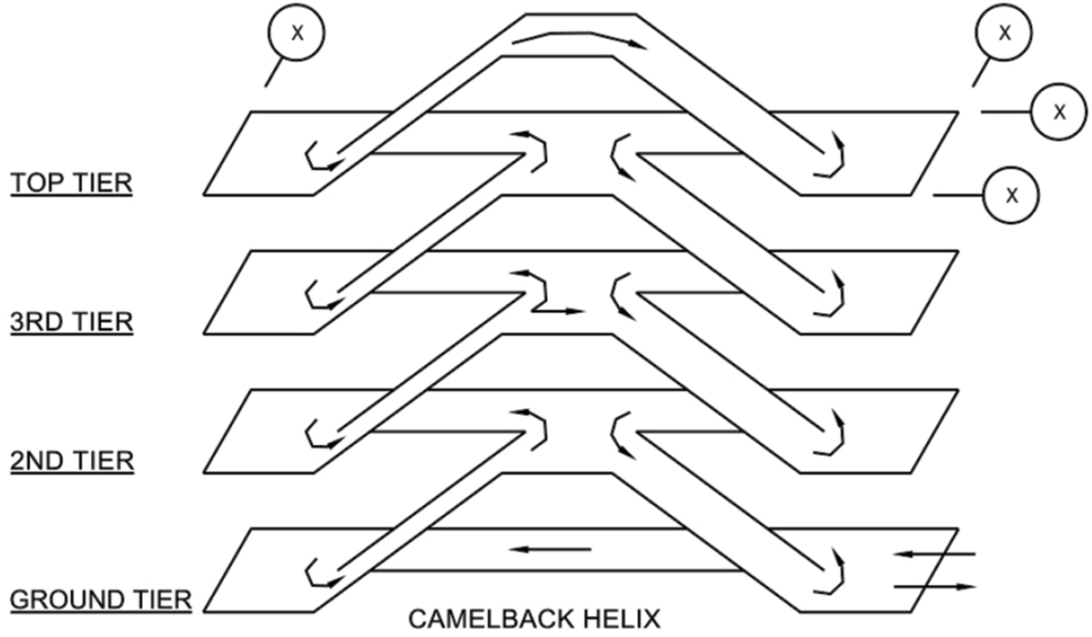 Figure 3: Isometric View of Camelback Helix circulation System
Precast-Prestressed System- Most precast parking structures are built with double-tees, which evolved from earlier precast flooring systems. The earlier double-tee design featured flange-to-flange connections and a field-placed concrete topping as the riding surface. Now, more recent double-tee systems are factory-topped which means that the entire deck thickness is integral as cast. The methods of joining the structural elements vary, but they must meet two performance requirements: structural strength and corrosion protection. While factory-topped double-tee systems are popular in most of the united stated, their use undergoes scrutiny in high seismic zones, where a monolithic topping is prescribed for the floor diaphragms.
Post-Tensioned System– A common floor and ramp system consists of one way cast-in-place concrete slab cast integrally with beams. The beams are supported on columns or on girders that, in turn, are supported on columns. In general, slabs, beams and girders are of post-tensioned concrete. With sloping floors, the columns in parking facilities have unequal story heights and are subjected to unusual forces compared to typical buildings. As shown in Figure 4, an interior column typically is short, off-set loaded from both sides with effects of pre-stressing, subject to high joint shears and moments associated with long-span construction, and subject to effects of volume changes. Cracks may develop in the beam-column joints due to inadequate confinement of the joints.
Diaphragms– A floor system provides a shear diaphragm and distributes in-plane horizontal forces to the lateral load resisting elements. When a parking structure has one or more sloping ramps, the diaphragm can be divided into sub-diaphragms. For example, the diaphragm in Figure 7 consists of three sub-diaphragms per floor for the lateral load acting perpendicular to the long direction. Whether or not a diaphragm or a sub-diaphragm can be assumed to be rigid depends on several factors, such as span-to-depth ratio of the slab, plan dimensions relative to the location of the lateral load resisting elements, slab thickness, locations of openings and discontinuities in the slab. Each sub-diaphragm should be designed separately so that it can resist its share of the load. If diaphragms are inadequate in transferring the lateral load to the seismic frames or shear wall, the results can be disastrous. Figure 8 shows a precast parking facility that collapsed due to inadequate diaphragm action during the 1994 Northridge earthquake.
Ramp Trusses– In a parking structure with ramps where floors slope and form a truss, the truss action can provide lateral resistance. As Figures 1 and 7 show, the sloping ramps may act as cross-bracing. A well-defined load path is required to properly transfer the loads to the ground. It is essential that the sloping ramps be connected at the lowest extremity of the structure, by proper detailing, to transfer the load to the underlying ground base. Though bracing action helps carry lateral forces to the ground, care should be taken so that it does not cause an unanticipated volume change restraint.
Unique Loads
The members of a structural system should be designed and connected to resist wind and seismic loads and corresponding movements. In precast parking facilities, a major issue is proper connections between various components of the structure establishing load path from floor masses to the foundation. In post-tensioned facilities, ductility of the post-tensioned elements has been a concern. In addition, the code requires that parking structures be designed and detailed to accommodate volume changes which include creep, shrinkage, axial shortening and temperature effects. Designing a parking structure for both seismic and volume changes can be a challenge in some cases.
Volume Changes
The common “open” parking structures require access to external air and, therefore, they have a large percentage of the façade open. With open-air circulation, they are subjected to volume changes which include creep, shrinkage and temperature changes. The ability of a structure to “breath” is imperative because volume changes in a parking structure will always occur. The magnitude of anticipated volume changes may differ based on where the structure is located as well as the type of construction employed.In precast structures, much of the shrinkage and creep shortening occurs at the precast plants before precast elements are erected, and, therefore, their net effect on the completed structure is considerably reduced. Further, the connections used in precast construction help mitigate the volume change effects. However, since the post-tensioned structures involve cast-in-place concrete construction, they undergo all of the creep, shrinkage and temperature changes from the time concrete sets. In addition, axial shortening effect of post-tensioning needs to considered.
 Figure 6: External Helix Ramp Raleigh-Durham Airport
Structural Restraints and Cracking
The volume change forces develop only if the deformations associated with volume changes are restrained. Structural systems inherently introduce restraint to the volume changes causing cracks in the structure. The restraint caused by vertical elements such as shear walls and columns can be significant and cannot be ignored in design. The restraint can cause cracking of floor slabs, beams, columns and walls, and if left unattended, can allow deterioration. A challenge in parking structure is to provide necessary structural strength while allowing the structure to flex under volume changes and keeping the project economically feasible. To deal with the volume change forces, the engineer in responsible charge should detail with following considerations:- Provide isolation or expansion joints at reasonable intervals,
- Avoid stiff elements at the end of the structure,
- Limit the size of concrete pours,
- Isolate the frame action from stiff walls.
- Reduce the rigidity of restraining elements and connections, and
- Install temporary open “pour strip” joints that are closed before construction is completed.
Drainage
Parking structures are exposed to rain, and in some cases, ice and snow. In areas on or adjacent to seashore, salt spray, salty sand, and high-moisture conditions can cause a serious corrosion situation.The ACI-362 recommends that for control of surface water, floor slabs be designed such that water flows to the floor drains without ponding. The floor deflection and camber need to be considered in design of the drainage system. The code requires that floor system to be designed and constructed to prevent negative camber under dead load.
Drains are needed in all parking structures, located at low points on each floor to catch water from any source. Drain covers and other component should be strong enough to support vehicle wheel loads. Drainpipes should be adequate to take the run-off water from roof and floor levels. Below-ground drainage is usually in flexibly-jointed pipe work leading the water to a two- or three-stage oil interceptor before discharging it into the surface water sewer. The construction documents need to show the floor spot elevations to depict the drainage pattern and drain locations.
 Figure 7: Double Threaded Ramps Veterans Hospital Tampa
Durability
Concrete has low tensile strength, is prone to cracking and not inherently watertight. In parking facilities, there are three causes of concrete cracking: structural behavioral cracks, volume change cracks, or corrosion-induced cracks.Because parking structures are open to elements, their structural components are subject to more hostile environment than components of other buildings. As such, they require special considerations for crack control and durability. The environment where concrete is subjected to freeze and thaw cycles, air entrainment of concrete has been used to reduce the scaling caused by the freeze and thaw cycles. The maximum nominal aggregate size is a significant factor in determining the air entrainment requirements. Adequate drainage and concrete sealers and coatings can also reduce freeze and thaw scaling.
Non-prestressed concrete parking structures are known to deteriorate faster than their prestressed counterparts. The chloride ion level in concrete is a major factor in the corrosion of reinforcing steel. The chloride ions may be present in the original concrete mix ingredients. The ACI-318 suggests water-soluble chloride limits before service, depending on the type and use of the member. Further, steps should be taken to reduce or delay the steel reinforcement corrosion.
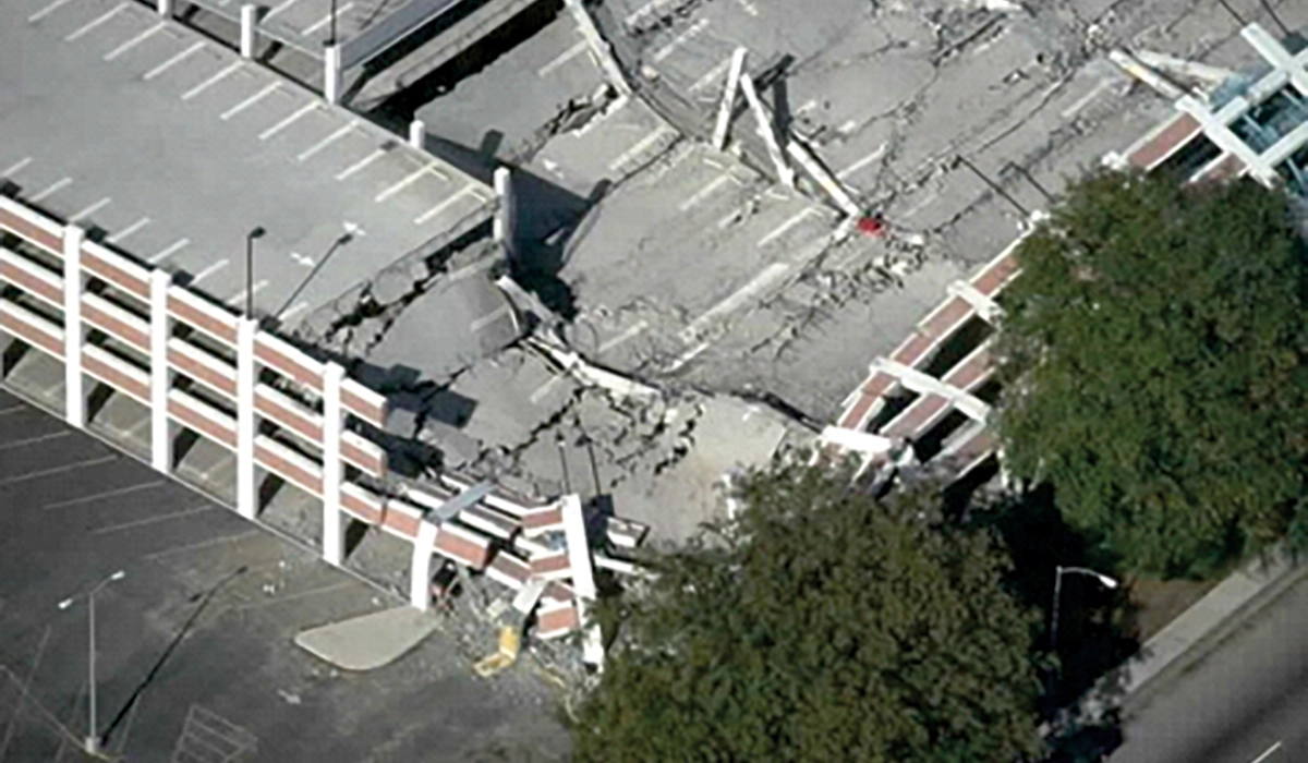 Figure 8: Parking Garage Collapse during the Northridge Earthquake due to Diaphragm Failure (Courtesy of S. K. Ghosh and Associates).
Joints
Concrete construction involves joints to permit limited structural shortening. The joints can be construction or control joints, and isolation or expansion joints. Due to exposure of parking facilities to the elements, joints are of critical importance in crack control. However, joints are often source of leakage through the slabs in parking structures. Joint fillers and sealants are used to accommodate the anticipated movements and seal the joints. Expansion joints are provided when movement in a direction is expected to exceed the capability of a joint sealant. Expansion joints are designed to accommodate the volume change and structural movements. The width of the expansion joints is selected with consideration of the ambient condition at the time of installation. Figure 9: A-Tampa General Hospital
Pedestrian and Motorist Safety
To avoid skidding and slipping, the codes require the concrete slab surface to have a minimum coefficient of friction of 0.5. For this purpose, concrete slab surface generally needs broom finish, except at steep ramps where a rougher screeded finish with screeding at right angles to the traffic flow may be needed. Two coats of surface hardeners should be applied to all exposed floor areas.In addition, two types of guardrails are needed: one for vehicles and the other for pedestrians. At perimeter of a structure and in other interior areas in the structure, where an elevation difference of 25.4 cm (12 inches) or greater occurs, a minimum of 50 cm (2 ft.) high vehicular restraint capable of supporting the 26.70kn (6,000 lbs.) impact load should be provided. For the pedestrians, a guardrail is needed where the elevation difference exceeds 57 cm (30 inches). The guardrails must comply with the applicable codes. The facilities accommodating trucks and buses need to be designed in accordance with an approved method that contains provision for traffic railing.
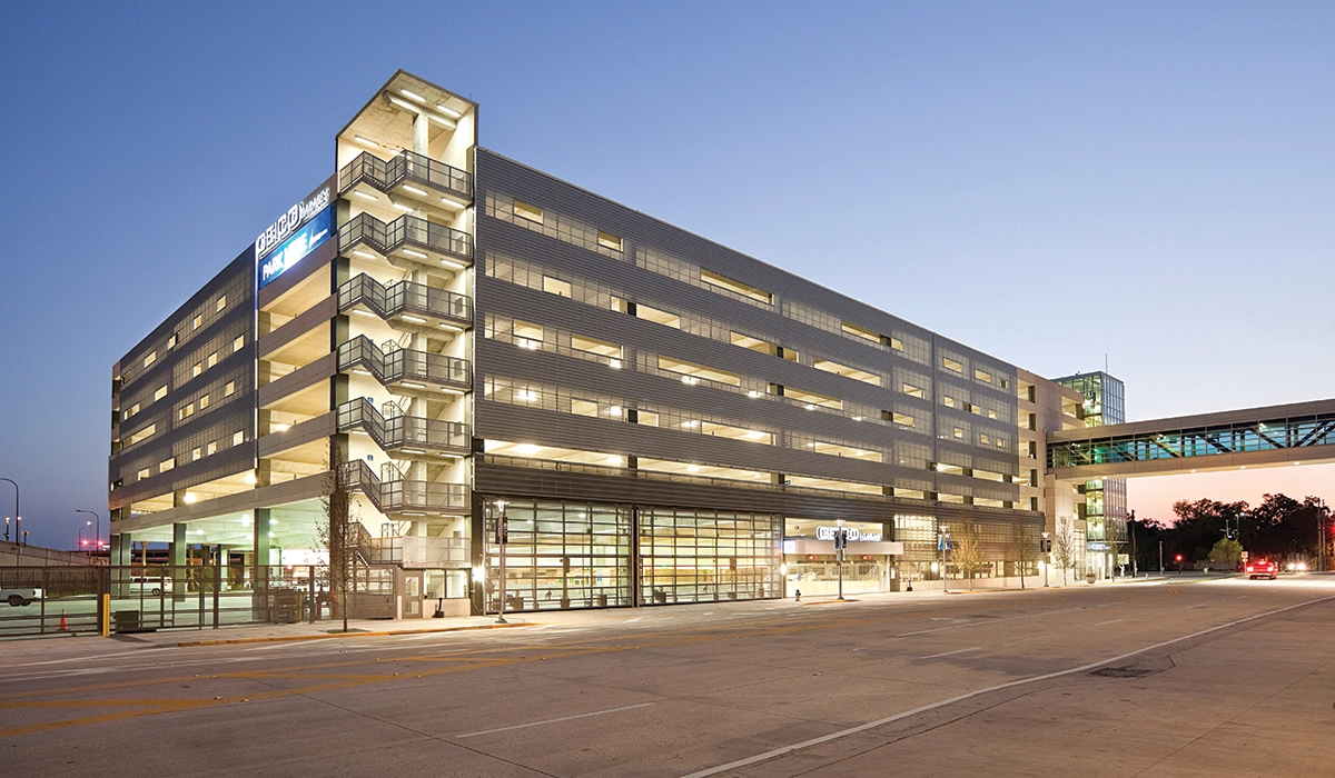 Figure 9-B: GEICO Garage Lighting for Security
Lighting and Way-Finding
Success of a parking facility is greatly dependent on user perception of comfort and safety. See examples in Figures 9 A & B. Adequate lighting intensity and uniformity combined with clear, readable and appropriately placed way-finding signage is crucial to the safety and comfort of the user as a driver as well as the user as a pedestrian (Figure 10). Minimum lighting standards for parking facilities are covered under publications IESNA-RP20.98 and IESNA-G1.03.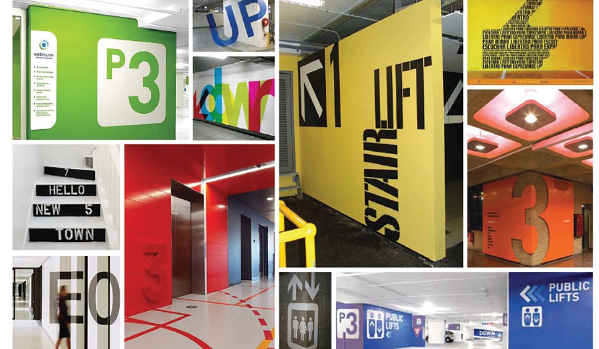 Figure 10: Way Finding / Signage
One of the major developments in the past ten years has been the use of parking guidance systems (Figure 11) to manage the parking spaces more effectively and assist the driver to find a space quickly. Customers can quickly and easily see the available spaces not just in each aisle but they are also guided to the last space in the car park.
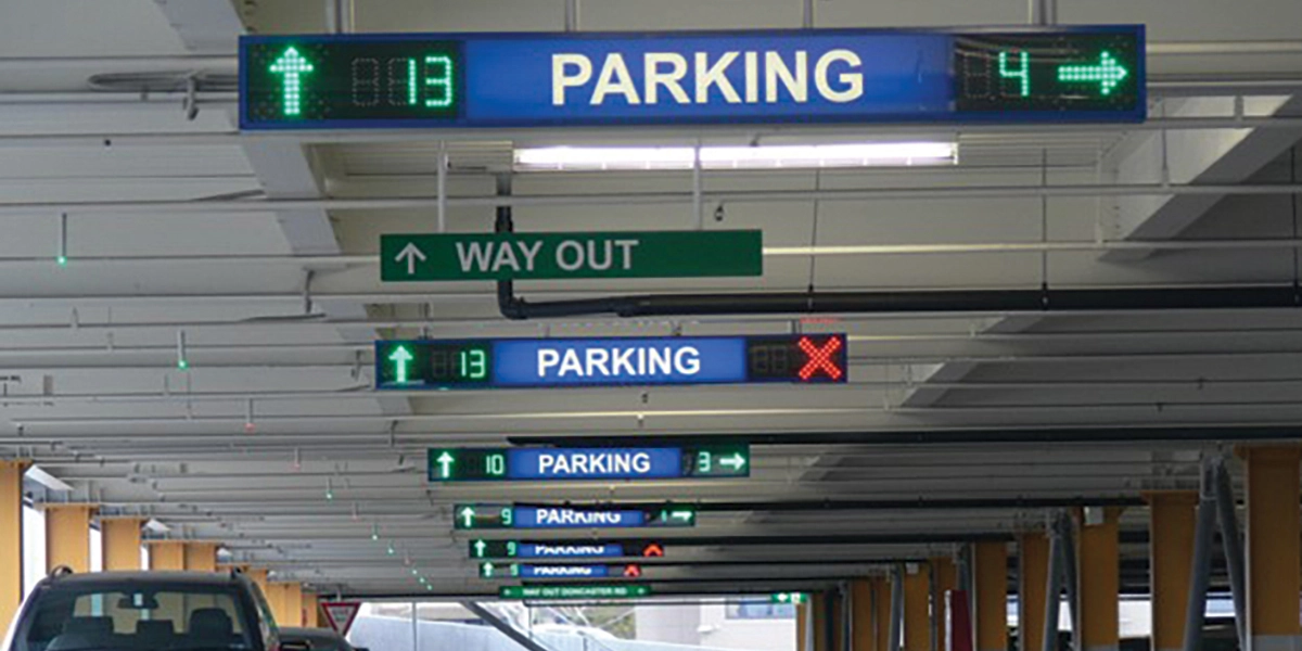 Figure 11: Parking Guidance System
Conclusions
This paper provides an overview of the state-of-the-art in design and construction of parking facilities in the United States. Both precast-prestressed and post-tensioned concrete structures are discussed with emphasis on structural design for gravity and lateral loadings, volume changes effects, durability and safety considerations. The design of parking structures is a major challenge due to conflicting requirements of structural stiffness and volume change effects for which detailing guidelines are available. Parking layout, lighting and way-finding are crucial to a successful project.References
- Chrest, A. P., Smith, M. S., Bhuyan, B., Iqbal, M. and Monahan, D. R., Parking Structures – Planning, Design, Construction, Maintenance and Repairs, 3rd Edition, Kluwer Academic Publishers, Boston, Massachusetts, 2001.
- ACI Committee 362, (2012) Guidelines for the Design and Construction of Durable Concrete Parking Structures, American Concrete Institute, Farmington Hills, Michigan.
- Iqbal, M., (2007) “Thermal Movement in Parking Structures”, Structural Journal, American Concrete Institute, Farmington Hills, Michigan.
Published on:
13 November 2017
Published in: NBM&CW November 2017
Share:
We Value Your Comment