Repair and Rehabilitation of A Minor Bridge in Shravasti District (UP), India
K.K. Pathak, Professor, P.K. Singh, Ex-professor, Abhishek Sharma, Research Scholar, Dept. Civil Engineering, IIT (BHU), Varanasi, India, Ravish Raj, Undergraduate Student,Dept. Civil Engineering, IIEST Shibpur, Howrah, India
Scour is a natural phenomenon caused by the erosive action of flowing stream on alluvial beds. Failure of bridge due to scour at their foundations, which in this case consisted of abutments and pier, one 1.2 dia, 18m deep pile, is a common occurrence. According to Ahmed and Rajaratnam (2000), the bed shear stress near nose of the wing-wall and abutment is amplified by nearly 3.6 times the bed shear stress of approaching flow. Garde et al (1961) concluded that the flow Froude number for the normal channel flow adequately represents the effect of approaching flow velocity on the maximum scour depth. Kandasamy (1989) showed that the scour depth increases with increase in flow depth due to incorporation of the flow Froude number.Laursen (1958, 1960, 1963), Gill (1972), Wong (1982), Tey (1984),Kwan (1984), Kandasamy (1989) and Melville (1992, 1995, 1997) considered shear velocity in their approach. Dongol(1994) conducted an extensive series of experiments to study the effect of approaching flow velocity on scour depth at vertical-wall, wing-wall and spill-through abutments under live bed conditions in uniform and non-uniform sediments. His results are complimentary to the studies of Chiew (1984) and Baker (1986) for live-bed scour at bridge piers in uniform and non-uniform sediments, respectively. Dey and Barbhuiya (2004a) reported that for smaller flow depths, the equilibrium scour depth increases significantly with increase in flow depth, whereas for higher flow depths, equilibrium scour depth is independent of flow depth.Kandasamy (1989) pointed out that if the length of the abutment is increased, the opening ratio decreases, and the effect on scour depth of such a change can be ascribed to both a decrease in contraction ratio and an increase in abutment length.
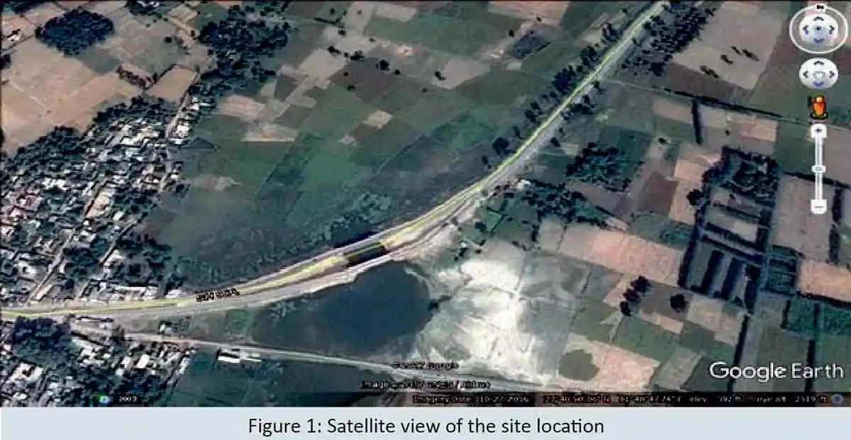
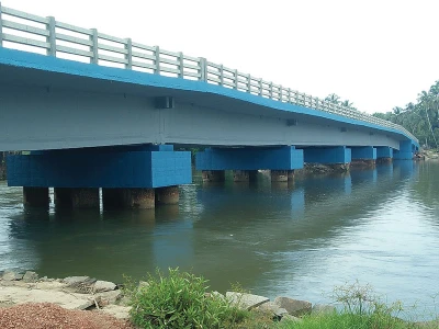
Two parallel minor deck slab bridges of span 36.0m each exist side by side at km 24.3 of BBSC road in District Shravasti, U.P, India (fig. 1). The bridges consist of 4-spans of 9.0 m each, over two abutments at the ends and 3 wall type piers in between. The RCC abutment and piers are founded over 1.2 m diameter 18.0 m deep piles as per details shown in Fig-2(a).
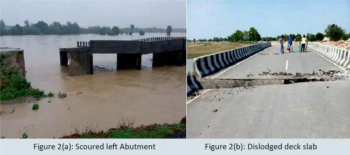
During monsoon in the year 2017, due to release of excess water from Rapti barrage there was sudden increased discharge in the stream over which the minor bridges exist. On the upstream side of the bridges, there was ponding due to backwater. The water level difference between the upstream and downstream of the bridges caused increased water velocity in the stream, resulting in accelerated scouring. The downstream bridge had some bed protection due to dumping of stone boulders and sand bags during the scour, and therefore, it was prevented from any major damage and it was saved. The upstream bridge was not so well protected and major scouring occurred near the right abutment and the adjacent pier, causing tilting and settlement of the abutment and the pier near it. This resulted in tilting of slab over the end span and damage of nearby approach slab. As a result, out of the two bridges, the upstream bridge became unserviceable and it was closed to traffic. The site was inspected by the consultants (Authors 1& 2) on 12th Nov. 2017.
Since the two bridges connect Bahraich and Bhinga, which are two district headquarters of Uttar Pradesh (Fig.1) closure of one of the bridges became vulnerable. The downstream bridge, which was saved from major damage and remained the only connecting bridge between Bahraich and Bhinga, and it also needed protection against scour before the next monsoon.
As major scour in the downstream bridge was successfully prevented by dumping of boulders and sand bags, it was concluded that the streambed, if suitably protected by proper bed and side protection, any future scour due to increased flow can be successfully prevented.
Damages in the Upstream Bridge
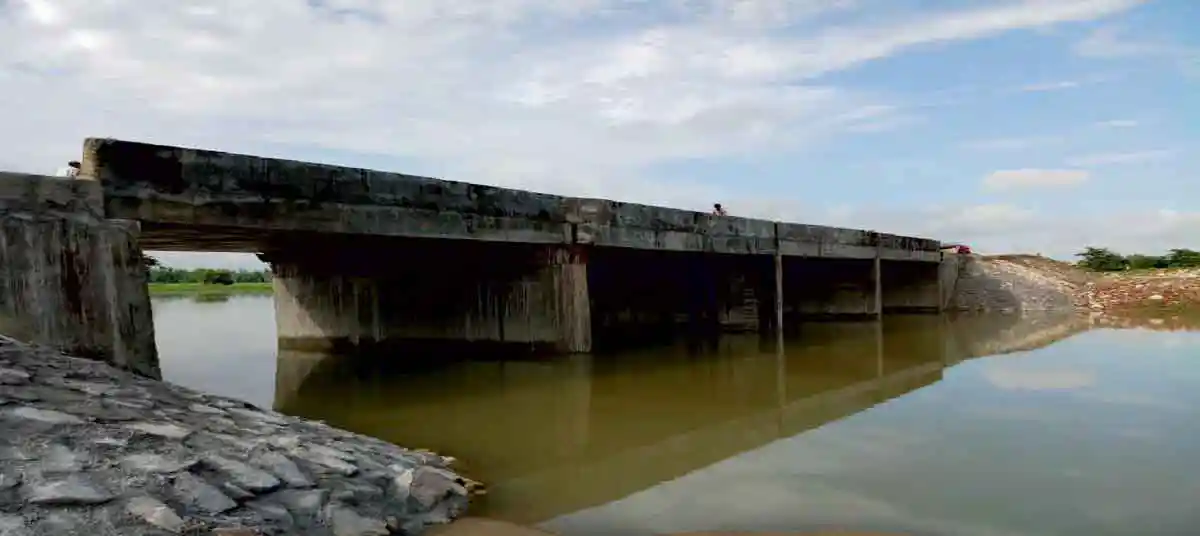
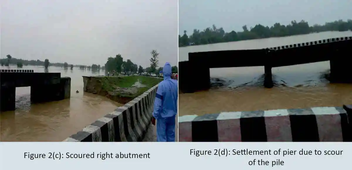
The major damage consisted in scour of the right abutment and the adjacent pier foundation, resulting in dislodging of the deck slab resting on these. During scouring, as the scour around the piles increased, the frictional resistance to piles from soil decreased, causing their tilting and settlement. No structural damages to deck slabs, abutments, piers, piles and pile caps werereported. However, the approach slab was damaged due to scour of embankment below it (Fig.2-b,c,d)
Repair and Remedial Measures
Survival of the downstream adjacent bridge due to opening of gates of Rapti barrage and high discharge in the stream indicated that there was no major design fault in the bridges. If suitable bed and side protection works are carried out, foundation scour and scour of the approach roads can be controlled successfully.
Bed and side protection against scour
Before carrying out the bed and side protection works, suitable packing around the exposed piles, up to the stream bed level was necessary. Also, cutting or filling of the bed, and embankment sides up to the bed level, was carried out. Local coarse grained well compacted cohesive soil in layers, was used for the filling in the bed and around the piles of the two bridges which were not damaged due to excessive scour.
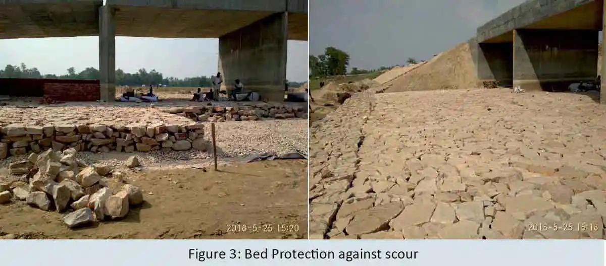
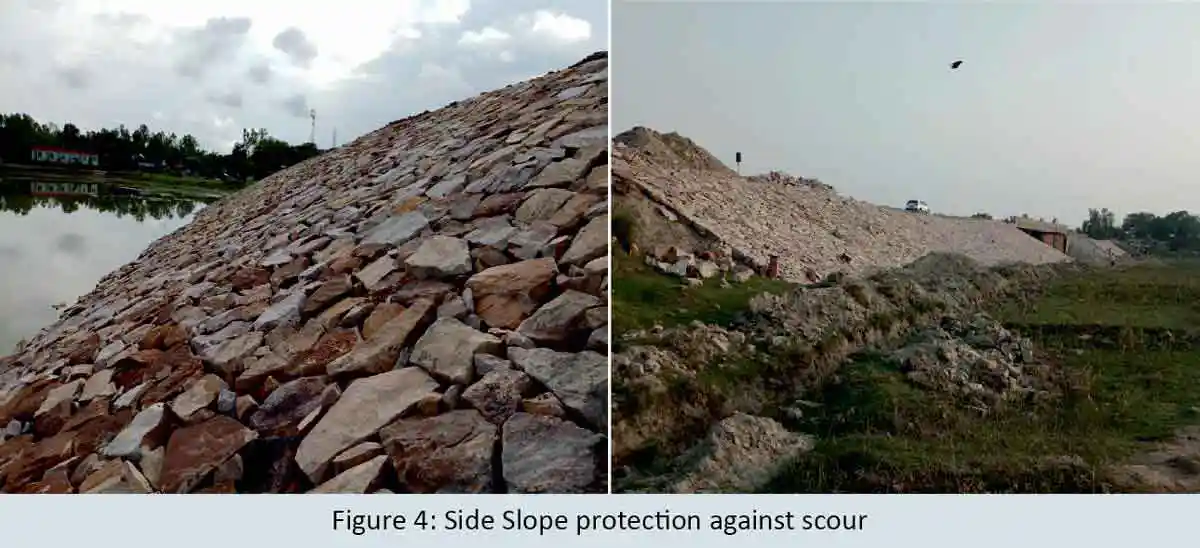
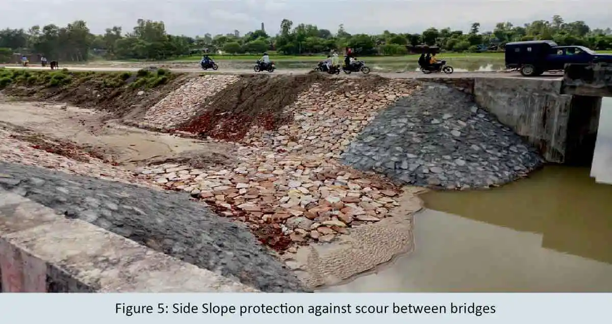
Strengthening of the bed and sides of the embankments up to HFL plus free board was done by laying 200mm thick GSB layer (20.0 mm maximum size)and using geo-grid. The GSB was dust free to allow free seepage of water through it. Over the 200 mm thick GSB layer, 500mm thick 40kg boulder pitching was provided to prevent the GSB from flowing away. Top 20 cm of the voids in boulder pitching was filled using M-25 grade concrete. Thus, the stream bed and side slopes of the approach roads were prevented from future scour.
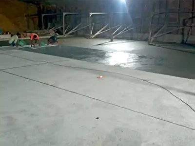
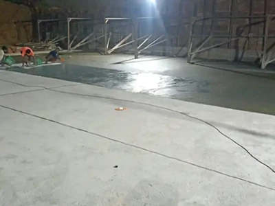
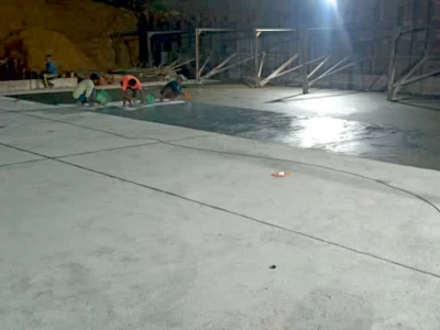
The bed pitching, also acting as launching pads, was continued up to 13 m from pile caps on the upstream side bridge, and 10 m on the downstream side of the downstream bridge. In the outer 2 m wide strips of the pitching, wire crated boulders were used (Fig.3,4,5).
Packing around the scoured piles:
Accelerated scour around group of piles took place, and the 1.2m dia. 18 m deep piles were scoured up to an approximate depth of 12 m, leaving only 6 m grip, which leads to sinking and tilting of the abutment.
As the piles transfer the load to the sub strata soil, a reasonably strong and economical material, which may stick to the piles by friction and bonding as well as it suitably transfers the load to the surrounding soil,wasrequired as the packing material around the damaged abutment and the adjacent pier piles. Medium grained local sand in 1:8 cement-sand mix by volume using PPC was used for packing around the exposed piles. The cement sand mortar was well compacted around the pile in layers, so that it develops proper bonding and friction with the piles and successfully transfers the pile load to the adjacent soil strata. Tremie was used for under water mortar application, so that the cement in the mix is not dissolved and carried away in the water. Mortar application in layers with proper compaction shall be carried out. Scour around the abutment and adjacent pier piles in excess of 2.0 m distance from the outer piles after mortar packing was filled with well-compacted local cohesive soil.
Settlement and tilting of piles and abutment
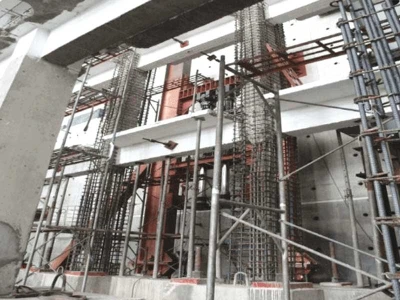
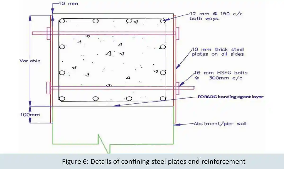
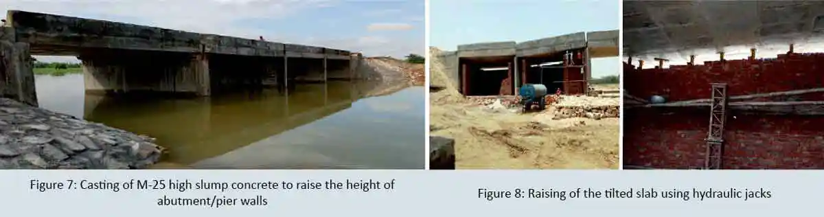
No structural deficiency was reported in the settled abutment and piles, and therefore, only the desired top levels of these was restored before reseating the deck slab. Confining steel plates (Fig. 6) was used for casting M-25 high slump concrete using super plasticizer with 43-Gr OPC. Reinforcing steel cage of 12mm dia. bars @ 150 mm spacing was used to raise height of the abutment/ pier walls as per actual requirement.
Raising of the tilted deck slab
The tilted deck slab of the end span was raised suitably to make it horizontal with the help of requisite number of hydraulic jacks. Steel tube temporary scaffolding was used for it. After raising the deck slab, confining steel plates and reinforcement cage was put in position. Using specified concrete, concreting of the walls up to the desired level was carried out. The confining MS plates were tightened with 16 mm dia. HSFG bolts used at 300 mm center to center, both at top as well as bottom, and left in position.
Crash barrier
Crash barrier, wherever necessary, was dismantled and a fresh barrier shall be constructed in line with the remaining crash barriers.
Deck top
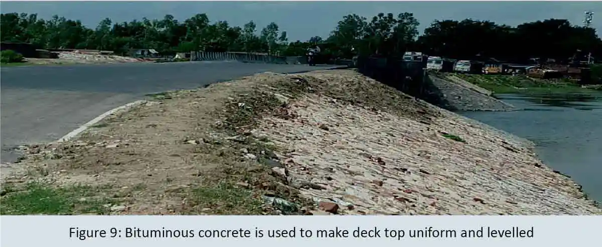
Bituminous concrete was re-laid over the deck to ensure uniform road level and smooth ride on the bridge.
Approach slab and embankment
The approach slab was recast after raising the embankment to the required height and protecting it with boulder pitching up to HFL plus free board. The back fill behind the abutment was carried out as per BIS specifications.
Conclusion
The increased velocity and discharge in the stream due to diversion of excess water from Rapti barrage during 2017 monsoon, stream bed and embankment side scour at the bridge site took place, leading to failure of the upstream bridge. Damage to the downstream bridge was prevented due to dumping of boulders and sand bags. Therefore, it was imperative to protect the streambed by suitable pitching before 2018 monsoon; otherwise, a similar flood situation as in 2017 may damage both the bridges completely. This might cause disruption of the crucial road traffic between Bahraich and Bhinga.
The consultants provided technical recommendations for repair and rehabilitation of the bridges as given above. An estimate for repair and restoration including bed protection for the two bridges was prepared by the Provincial Division UP PWD, Shravasti which was taken up for timely construction after its suitable checking and tendering by experienced and registered bridge contractors.
The upstream and downstream two bridges are rehabilitated and open to traffic before 2018 monsoon. No scouring during 2018 and 2019 monsoon floods are reported and the two bridges are functioning well.
References
- Ahmed F, Rajaratnam N,(2000) Observations on flow around bridge abutment. J. Eng. Mech., ASCE 126: pp51–59.
- Baker R E, (1986) Local scour at bridge piers in non-uniform sediment. Rep. No. 402, School of Engineering, University of Auckland, Auckland, New Zealand.
- Barbhuiya A K,(2003) Clearwater scour at abutments. Ph.D thesis, Department of Civil Engineering,Indian Institute of Technology, Kharagpur.
- Barbhuiya A K, Dey S, (2003) Vortex flow field in a scour hole around abutments. Int. J. Sediment Res.18:pp 1–16.
- Chiew Y M,(1984) Local scour at bridgepiers. Ph.D thesis, University of Auckland, Auckland, NewZealand.
- Dongol DMS, (1994) Local scour at bridge abutments. Rep. No. 544, School of Engineering, University of Auckland, Auckland, New Zealand.
- D S PrakashRao, Design Principles & Detailing of Concrete Structures.
- Garde R J, Subramanya K, Nambudripad K D,(1961) Study of scour around spur-dikes. J. Hydraul. Div., ASCE 87: pp 23–37.
- Gill M A,(1972) Erosion of sand beds around spur-dikes. J. Hydraul. Div., ASCE 98: pp 1587–1602.
- Kandasamy J K,(1989) Abutment scour. Rep. No. 458, School of Engineering, University of Auckland, Auckland, New Zealand.
- Laursen EM, (1963)An analysis of relief bridge scour. J. Hydraul. Div., ASCE 89: pp93–118.
- Laursen E M, Toch A,(1956) Scour around bridge piers and abutments. Bull. No. 4, Iowa Highways Research Board, Ames, Iowa
- MelvilleBW, (1992) Local scour at bridge abutments. J. Hydraul. Eng., ASCE 118: pp615–631.
- Melville B W, Sutherland A J,(1988) Design method for local scour at bridge piers. J. Hydraul. Eng., ASCE 114: pp 1210–1226.
- N. Krishna Raju - “Advanced Reinforced Concrete Design”, CBS Publisher and Distributor, Delhi, 3rdEdition, (2003).
- Park, R., and Gamble, W. L. (2000). Reinforced concrete slabs, Wiley, New York.
- SP 16, Design Aids for Reinforced Concrete Structures, IS 456 1978, Bureau of Indian Standards, New Delhi 1980.
- Tey C B,(1984) Local scour at bridge abutments. Rep. No. 329, School of Engineering, University of Auckland, Auckland, New Zealand.
- Wong W H,(1982) Scour at bridge abutments. Rep. No. 275, School of Engineering, University of Auckland, New Zealand.
Published on:
09 June 2021
Published in: NBM&CW June 2021
Share:
We Value Your Comment