Concrete Tunnel | Concrete Structures | Metro Railway tunnels
Introduction
Conventional concrete, which can be considered to be an artificial rock, is not intrinsically waterproof. It absorbs water. The rate of absorption depends upon many factors, including the porosity of concrete. In addition, excessive contents of water-soluble alkalis in cement (as in the case of Indian cements of recent periods) can make concrete highly absorbent1-4. Today’s concrete structures, compared to concrete structures of earlier decades, also suffer from higher thermal and shrinkagestresses and the resulting cracks1-5. The result: water retaining structures, e.g., tunnels, subways, basements, etc. are characterized by water seepage and leakage unless such structures will be effectively waterproofed.
Besides general porousness or permeability, local defects or discontinuities, and besides the existence of planned structural gaps (expansion joints), the waterhead outside the structure greatly influences the rate of water leakage into underground structures. Thus, there will be many tunnels which may exhibit little or no water leakages during the dry season whereas the same tunnels may show profuse water leakages during the wet season of the year or when there will be flooding of grounds surrounding the tunnels.

In addition to ungainly sights, operational difficulties and damages to contents, etc., water leakages, seepages and dampness adversely affect the durability of tunnels and other concrete structures, as even minor dampness can lead to an early ruination of the structure by accelerating the process of corrosion in rebars and thereby inviting conditions of distress in the structure.
The Essence of Surface Protection
Kar1-14 highlighted the problem of early decay and distress in concrete structures that could be encouraged by the dampness in concrete or even by the exposure of the concrete structure to the general environment. In most cases of concrete structures, it is corrosion in reinforcing bars and prestressing elements, that leads to conditions of distress in such structures.The Indian standard IS 456:200015 recognizes the problem of early distress in concrete structures as well as the causes for such early distress when it states in its Clause 8, Durability of Concrete: "One of the main characteristics influencing the durability of concrete is its permeability to the ingress of water, oxygen, carbon dioxide, chloride, sulphate and other potentially deleterious substances." The interior surfaces of tunnels are generally exposed to air and thus these surfaces, if not protected, will permit the ingress of oxygen and carbon dioxide. While the diffusion of carbon dioxide may lead to depassivation of reinforcing bars, making corrosion in such bars possible, the diffusion of oxygen into the structures will lead to corrosion in the rebars in the presence of the moist environment inside the structure.
As a solution to the problem of early distress, Kar1-14 recommended the prevention of the ingress of water into or flow of water through structural elements and the protection of all structural surfaces, exposed to either air or intermittently to water and air. The dual goal was to be achieved by the provision of waterproofing treatments on all exposed surfaces of structures. The Indian Standard15 followed suit when it wrote in its Clause 8: "The life of the structure can be lengthened by providing extra cover to steel, by chamfering the corners or by using circular cross-section or by using surface coatings which prevent or reduce the ingress of water, carbon dioxide or aggressive chemicals."
Kar12,13 explained why, among the four options recommended in IS 456:200015, the provision of surface coatings or other surface treatments to prevent the ingress or passage of water, and to prevent or reduce the diffusion of carbon dioxide and oxygen or permeation of aggressive chemicals, was the only viable option.

In order to make concrete structures durable, the exposed surfaces (i.e. all of inside surfaces of the tunnel) should be given a post-construction surface treatment to create an impermeable surface region that would, besides preventing water leakages and seepages, prevent the easy ingress of air (moisture, carbon dioxide, oxygen) into the structure. This is the essence of surface protection of concrete tunnels and other structures, and the surface protection is best achieved through the provision of waterproofing treatments on the surface of concrete structures. Though the most important objective of the provision of surface protection systems is to prevent or inhibit corrosion in rebars and prestressing elements of steel, it is not the recommendation of the writer to provide any surface treatment to such rebars or prestressing elements.
It need be emphasized in the context of durability of concrete structures that the mere absence of any visible sign of water leakage through a structure is not a proof of its being a waterproof structure. The development of conditions of distress in the columns in the middle of the tunnel (away from the leaking walls) of Metro Railway, Kolkata is an example.
A false impression of water tightness of a water retaining structure can also be created when the rate of evaporation of water from the structure is greater than the rate of ingress of water into the structure.
It must be recognized that most of the damages due to corrosion in rebars and prestressing elements inside concrete structures, adversely affecting the durability of such structures, will take place if there will be a moist environment inside the structure and air will enter into the structures15. in the absence of air even a lot of water inside a concrete structure may not cause much damage. This is exemplified in the virtual absence of any condition of distress in foundation structures of concrete, unless the ground water will be patently harmful for concrete.
Thus, whereas the absence of a surface protection system on the visible surfaces of a concrete tunnel is likely to invite conditions of distress early, the absence of any waterproofing system on the outer faces of the tunnel is not likely to cause any such problem in most of the cases.
It has thus become essential, specially in the case of today’s concrete structures, which are built with cement, with very high C3S/C2S ratios and excessive amounts of water soluble alkalis1,2, and with today’s high strength rebars with surface deformations1-5,11,16,17, that such structures be given surface protection (on faces exposed to the atmosphere) in the form of waterproofing treatments1-14 . The provision of such a surface protection system will arrest the leakage of water on a long term basis. It will also help fulfill the second objective of the prevention of water seepage at the post-construction stage. Furthermore, it will prevent or inhibit the ingress of carbon dioxide and oxygen. It may also prevent the ingress of chlorides and other aggressive chemicals. The process of corrosion in rebars and prestressing elements will thus be arrested or slowed down, leading to a lengthening of the life span of the tunnel structure and prevention of damages to other systems housed inside the tunnel.
Surface Protection for Tunnels and Other Water Retaining Structures
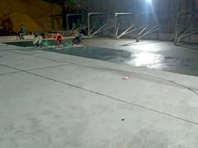
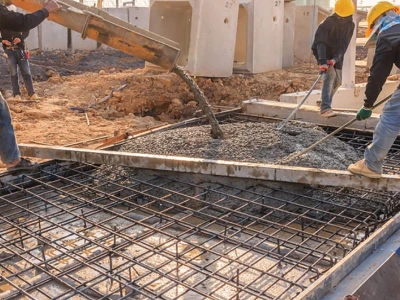
Against the prevailing practice of grouting for the purpose of arresting water leakages in underground concrete structures, Engineering Services International of Salt Lake City, Kolkata–700 064 pioneered in 1983 the concept and technique of waterproofing of tunnels and other underground structures with surface treatment (Figures. 1 and 2). According to this technique, no grouting or injection is strictly necessary for arresting running water leakages and for making the treated surface bone dry.In this scheme of surface treatment for underground structures, local treatments, instead of grouting, are provided on the surface to arrest running water leakages at construction joints honeycomb areas and at isolated locations. This is followed by the provision of a continuous waterproofing treatment on the entire surface in the interior of the tunnel. In the case of tunnels and other underground structures, the surface treatment for waterproofing is effectively provided in the form of a two-layer plaster.
It was observed in the case of the tunnels of Metro Railway in Kolkata, the Pedestrian Subway at Tollygunge, Kolkata and at many other sites with structures beneath the ground that when grouting or other methods of waterproofing had failed to prevent water leakages and seepages fully, the method of surface treatment with cementitious waterproofing compounds succeeded in making the concrete surface bone dry; thereby making the structures more durable.
A write-up on this technique of post-construction waterproofing treatment, with special reference to the surface protection to some difficult areas of the tunnel of Metro Rail in Kolkata can be found in Ref. 6.
This paper describes the technique of waterproofing treatment for the prevention of water leakage through reinforced concrete tunnels, similar to those of the tunnels of Metro Railway, Kolkata, the Pedestrian Subways at Tollygunge Station for Metro Rail, at Sealdah Station for Eastern Railway, at Kolkata Station for Eastern Railway, etc. The unique technique of surface treatment method, employed in the years 2000–01, to make the Pedestrian Subway at Sealdah, Kolkata, completely watertight (except at the expansion joints) and to simultaneously add years to the life of the structure, was developed and applied for the first time in 1983 to arrest water leakage through certain locations of the Metro Railway tunnels in Kolkata. The waterproofing treatments, provided on selected areas of the Metro Rail tunnels in 1983 and later in other areas in 1995, remain effective till date as a testimony to the long term effectiveness and durability of the particular cement-based surface protection system for underground structures.
In its coverage, this paper goes beyond the traditional concept of controlling or containing large volume seepage of water. It covers surface protection of concrete to create a bone dry condition inside tunnels. The surface protection, as opposed to grouting, helps to make concrete structures durable.
The transformation of leaky tunnels into zero-leakage structures is described in this paper with special reference to the Pedestrian Subway at Sealdah Rail Station, Kolkata.
The contents of this paper, though specially related to tunnels, are equally applicable to water reservoirs and underground facilities, like basements, machine pits, etc. The treated tunnels may be used as conduits for liquid, or these may carry people, traffic, materials or other systems.
Concept of Surface Treatment to Under–ground Structures
The transformation of a pervious underground structure into an impervious water retaining structure requires that a continuum with waterproofing materials be provided to the entire inner or outer surface of the structure. It is explained why it is so.Grouting No Help

It is recognized that particulate materials cannot be injected into a mass of concrete unless pores inside the concrete would be continuous and the size of the pores would be at least three times the size of the particles in the injection material. Cement cannot thus be injected into a concrete structure except at discontinuities, e.g., at cracks, defective construction joints, honeycombs, etc. As a result, grouting of cement, with or without admixtures, can at best seal cracks and honeycombs. It cannot generally arrest water leakages at all the locations of a large concrete structure, as in the case of a tunnel. It cannot prevent general seepage. It cannot prevent dampness and it cannot provide protection against the elements in the atmosphere.
Grouting can at best help to arrest water leakages at isolated locations. In the absence of a blanket coverage of the entire surface (either outer or inner) of the tunnel with an effective waterproof system, leakages will keep sprouting at new locations in a concrete structure as existing leakages will be arrested.
Grouting is not thus the surest way to make concrete tunnels waterproof.
Justification for a Surface Treatment
When the hull of a boat or a ship springs a leak, nobody injects any material into the leakage area. Instead, it is plugged or a piece of a plate is attached to the hull, covering the leakage area or the tear.The hull of a boat or that of a ship is a water retaining structure. So is a tunnel.
The concept of arresting water leakages through a boat hull or a ship hull can be applied in the case of a concrete tunnel with water leakages.
Furthermore, common sense would suggest that the isolated treatment through grouting cannot provide a continuous waterproofing barrier, let alone a barrier to the ingress of carbon dioxide and oxygen into a concrete structure. A continuum with such properties is necessary1-16to make the surface of a tunnel impervious and the structure durable.
Justification for Providing Treatment on Interior Surfaces of Tunnels

It will be so because the waterproofing system, with a continuous medium on the exposed (inner) surfaces of underground structures, will be relatively impervious to the entry of carbon dioxide and oxygen into the structure.
The provision of a waterproofing treatment on the interior surfaces of a concrete tunnel structure will thus prevent not only water leakages and the wash-out of the products of cement hydration and other components of concrete but also early corrosion in reinforcing bars. The treatment will consequently enhance the durability of tunnel structures of concrete.
Effectiveness of Surface Treatment
The Pedestrian Subway at Sealdah, Kolkata, following the provision of the surface waterproofing treatment on the inside of the tunnel in 2000–01, is recognized as a zero-leakage tunnel. The tunnel is still bone dry after eight monsoons, except at an expansion joint, which, this writer believes, should not have been provided. Surface treatment has provided the tunnel at Kolkata Station too with a zero leakage surface during the 2007 and 2008 monsoons. The surface treatments, which were developed by Engineering Services International in 1983 as a part of its PERMAKAR Technology, and which was provided at select areas of the Metro Rail tunnel in Kolkata in 1983 and in 1995, still remain effective as before, whereas the same tunnel, after extensive and expensive grouting with cement as well as cement, admixed with chemicals, or isocyanate chemicals, over the last two and a half decades, still suffer from a lot of water leakage at many locations. In the absence of a surface protection system in most of its areas, the tunnel (20–30 years old) required repairs, even in structural elements/surfaces which had no visible signs of water leakage.The fact that grouting methods of waterproofing, without the aid of surface treatments, may not be fully successful even in the stated task of waterproofing, is exemplified in the case of the Metro Rail tunnel in Kolkata and in the cases of innumerable other tunnels and other underground structures all over the country. It is recorded in the project report on Construction of Pedestrian Subway Opposite Tollygunge Metro Rly Stn. in Kolkata : "However, at temporary bored pile locations (total 8 locations), seepage of the leakage could not be stopped in the main subway with cement pressure grouting or Non-Shrinkable, Pumpable, Groutable (NSPG) chemicals due to which ‘PERMAKAR’ Technology (surface layer) treatment was adopted and seepage/leakage was arrested completely to achieve ‘bone dry’ condition."

Durability of Surface Treatment
Surface waterproofing treatments (Figures 1 and 2) provide a continuous barrier, which is essential for making underground structures waterproof and durable. The concept was pioneered by Engineering Services International in 1983. It has been observed in the case of the Metro Railway tunnels in Kolkata that surface waterproofing treatments, provided by the said firm twenty–five years ago in 1983 and in later years, are still fully effective. Similar observations were made on treatments provided at countless other establishments. Basic reasons for the durability of the PERMAKAR surface waterproofing system are : (1) the PERMAKAR waterproofing system is cement based and thus compatible with the basic material of construction of concrete tunnels and other underground structures, (2) cement is generally durable in water, and (3) the surface treatment itself adds years to the life of the structure by preventing the ingress of carbon dioxide and oxygen, the facilitator and the agent of corrosion. All of these add up to make PERMAKAR 3 surface waterproofing treatment durable.Specifications
As mentioned earlier, there are a few typical treatments for the waterproofing of tunnels and other water retaining structures. A set of standard specifications, the implementation of which led to the successful protection of tunnels, water reservoirs, basements, machine pits and other underground structures, can be found in Appendix-I to this paper.Pedestrian Subway at Sealdah
The Pedestrian Subway at Sealdah Station (Figure 3) is constructed of reinforced concrete. It has seven pieces of concrete boxes along the length of the tunnel. There is an additional exit structure (taxiway), in the transverse direction. Each of the five intermediate tunnel segments (16.4 metres wide) has three bays. The two side bays are separated from the 6.0 metre wide central bay by rows of circular columns. Besides the columns between the central bay and the two side bays, there are the exterior walls which support the floor slab and the roof slab.
The base and roof slabs were designed as flat slabs even though the slabs, with just four columns in each box, did not quite qualify as flat slabs. The columns were away from the ends of the boxes, i.e. away from the expansion joints. The cantilevered slabs yielded appreciably at the column strips, leading to the development of visible cracks along the long axis of the tunnel at the cantilever regions as the reinforcement became inadequate.
The surface treatment was found to be sufficient in preventing any water leakage along the cracks.
Figure 3 is a view of the central bay with shop fronts at the two side bays. The entry and exit segments (3 numbers, including the one at the taxiway) of the tunnel are single bay structures with wide stairs.
The length of the seven-segment subway, excepting the taxiway structure, is about 138.0 metres, and the height from the floor to the ceiling is 3.0 metres.
The interior of the subway, with its long and wide body, finished with plaster (as a part of the basic waterproofing system), and punctuated by circular columns, with tapered and circular renderings at the top, has an aesthetic appeal (Figure 3).
The tunnel was constructed according to the cut-and-cover method. A steel framework, covering the entire extent of the trench, was used to facilitate construction of the concrete structure. The steel framework was dismantled and removed following the construction of the tunnel structure. stubs of steel wide flange sections (H-sections), as remnants of this temporary framework, were, however, left embedded in concrete slabs at the floor and at the roof. The locations of these steel elements, wherever these penetrated the floor slab and the roof slab, became additional sources of troublesome water leakage. Similarly, steel rods, used to support stays/struts for the formwork for concreting the two walls, were left protruding from the floor. The penetration points (in concrete) of these steel rods led to water leakage (until these were treated as a part of the waterproofing treatment) from the floor.
Initial Observations
Initially, the elements of the Pedestrian Subway at Sealdah, as in most other cases of underground structures in environment with high water tables, had water leakages along the horizontal construction joints between different pours of concrete (e.g., at the interface of floor and side walls, different pours/levels of the walls, and at the interface of walls and the top slab), at isolated locations (point leaks) on the floor, walls and the ceiling, at a few honeycomb areas, along innumerable steel bar inserts (used to support formwork for the construction of walls) in the floor slab, at the locations of ends of steel H-sections (temporarily used to support side shorings, floor and ceiling) at the floor and the ceiling, and at the expansion joints between different segments of the tunnel structure.Waterproofing

There was no provision for the treatment of expansion joints as here were provisions for the provision of plastic water bars at such joints by the contractor who was engaged for the construction of the tunnel.
Subsequent to the appointment of the writer’s firm for the task of waterproofing treatment, steps were taken also to provide special treatments at (a) ends of H-sections at the floor and at the ceiling, (b) at base of the protruding steel rods at the floor, (c) at honeycomb areas and (d) at expansion joints such that the tunnel structure would be fully water-tight and dry.
The Treatment
Seven types of special treatments were provided from inside the box structure of the Pedestrian Subway at Sealdah to make it waterproof and thereby add years to the life of the structure- by preventing the flow of water through concrete
- by preventing the ingress of carbon dioxide and oxygen into the structure.
- arresting running water leakages as in point leaks (Figure 2A)
- treating full lengths of all the construction joints (Figure 2B) as much of the construction joints had running water leakages
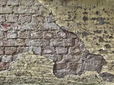
- treatment to honeycomb areas (Figure 2C)
- bar insert locations on the floor
- interfaces of steel H-sections and concrete at the floor and at the ceiling
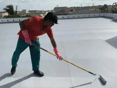
- surface treatment (Figure 1) to the entire interior surface of the tunnel
- expansion joints between segments of the tunnel.
Point Leak
The areas of point leak (Figure 2A) were plugged with cement, admixed with a quick-setting cementitious waterproofing compound and a liquid silica compound that hastens the setting of cement. A small groove was cut at the location of each point leak. A cementitious chemical (a powder chemical) was mixed with cement in given proportions. A quick-setting paste was made by adding water, and the liquid silica compound was mixed with the paste. This resulted in a quicker-setting cementing compound with improved properties for plugging concrete holes. The resulting material was used to plug the grooves at the locations of the point leaks.Construction Joint
The construction joints at bases and at tops of the walls (Figure 2B) and at junctions between different pours of concrete were treated to arrest running water leakage in the same way as it was done in the case of the point leakages, except that grooves were cut and plugged along the length of the construction joints. Waterproofing chemicals were similar to those which were used to arrest running water at areas of point leakages.Honeycomb Areas
Prior to the provision of surface treatments, the honeycomb areas (Figure 2C), highly prone to water leakages, as are point leakage areas and construction joints, were provided with special treatments to arrest running or probable water leakages following techniques similar to those which were adopted in arresting water leakages at locations of point leaks and at construction joints, except that the surface concrete was not chiselled out as deep as in the case of areas at point leaks and at construction joints.Bar Insert Locations
The bars, which were used only as an aid to facilitate construction and which had no place in the constructed tunnel, had their protruding portions sawed off and the surrounding areas were sealed as in the case of treating areas with point leakages.Ends of Steel H-section
The ends of steel H-sections, or of other metal elements, as remnants of temporary work (or even if those would be permanent features at the faces of the structure), created special difficulties in arresting water leakages, for the reason that concrete, used in the construction of the tunnel did not bond strongly to steel. The situation called for special formulations. The treatment, provided at the locations of the H-sections of steel, was a combination of several treatments. The treatment was provided at the interface of concrete and steel. Finally, the surface was provided with the two layer surface treatment with cement and an octadecanoic acid based cementitious water– proofing compound, preceded by the application of a cement slurry, enriched with a co-polymer of acrylic-styrene as a means to improve the bond between the exposed surface of steel and the surface treatment.Surface Treatment
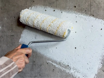
The surface treatment (Figures 1 and 2) was provided in the form of a two-layer plaster. The first layer was a 6.0 mm thick plaster of a combination of an octadecanoic acid based cementitious waterproofing compound and cement in the weight ratio of 3:50. The 8.0 mm or 12.0 mm thick cover plaster was of cement: sand (1:2 to 1:3). Point leakages and other running water leakages at construction joints, honeycomb areas, inserts and expansion joints having been arrested, the purpose of the surface treatment was to ward off any future leakages of water and to provide a completely dry environment inside the tunnel. The provision of the surface treatment served the other purpose of preventing the ingress of carbon dioxide and oxygen into the structure.Normally, the thickness of the cover plaster at ceilings and at walls is 8.0 mm whereas it is 12.0 mm on the floor. Similarly, the cement-sand ratio for the cover plaster and thickness of the first layer of octadecanoic acid based cementitious waterproofing compound and cement can be varied to meet specific requirements of individual cases of water retaining structures. Tests at National Test House, Kolkata, according to the provisions of IS 2645:1975 and IS 2645:200318, have consistently shown that the surface treatment (even with smaller thicknesses of 4 or 5mm) for waterproofing with the octadecanoic acid based cementitious water– proofing compound of proprietary formulation is impermeable under a waterhead of 20.0 metres. The 5 mm thick waterproofing treatment with octadecanoic acid based cementitious waterproofing comp– ound, when tested also under a waterhead of 40.0 metres for 8.0 hours at National Test House, Kolkata, was found to be impermeable.
The provision of the cement-based surface treatment requires a good bond with the existing concrete surface.
Several options could be considered for an improved bond. These include (a) chiselling the entire surface (as opposed to the conventional practice of making occasional pock marks), (b) roughening by etching with acid, (c) roughening with water jets, and (d) the use of polymers. The second option was selected in the case of the work at the Pedestrian Subway at Sealdah. It is explained later in the paper. In the case of the subway at Kolkata Station, the surface was roughened by etching with acid in some areas whereas polymer was used to improve the bond between the structure and the waterproofing plaster in other areas.
Expansion Joint
Expansion joints were provided in the construction of the tunnels of Metro Rail, Kolkata. After decades of trying, various techniques and material the leakages at the expansion joints are yet to be prevented totally. As a copy of the scheme, it was planned to provide similar expansion joints in constructing the tunnels of the Pedestrian Subway at Sealdah.This writer has maintained that
- it is unnecessary to provide any expansion joints in concrete tunnels on consideration of the length of tunnels; any thermal or shrinkage strain or stress is independent of the length.
- the provision of expansion joints is tantamount to an admission of foundation sliding failure of tunnels
- the provision of expansion joints in concrete tunnels invites unnecessary (in view of item (a) above) problems of water leakages which may be difficult to arrest fully
According to the original scheme of construction, the contractor, engaged for the construction of the tunnel, had provided rubber water bars at the expansion joints as it was used in the case of the tunnels of Metro Rail, Kolkata. It could be seen that there were gaps (even large pockets, between the water bars and the concrete underneath. The water bars, put in position at the time of concreting, could not prevent the leakage of water at the joints as, besides the large gaps between the water bars and the concrete, there could be no bond between concrete and the plastic elements of water bars.
The expansion joints, provided in the case of the pedestrian Subway at Sealdah, had variable widths up to 100mm. Even if expansion joints were required, no computation could have shown the need for such wide joints. The same mistake was committed in the case of the tunnel at Kolkata Station and the contractor, engaged for the treatment of the expansion joints, struggled for over a year without total success.
The expansion joints at the Pedestrian Subway at Sealdah called for various types of treatments.
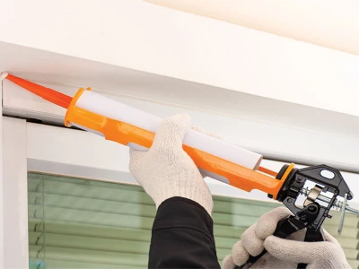
The expansion joints at Sealdah were re-treated by caulking of leadwool at fine openings, preceded by the application of quick setting cementing compounds and epoxies (insensitive to water) at wide openings. As the contractor, engaged for the construction of the tunnel, had provided boards in the joints, the quick-setting cementing compounds were provided for a depth of about 50mm. Minor leakages persisted in three of the six joints. This leakage at the three joints was finally arrested by injecting cement-based non-shrinking crack sealing compound, admixed with a bonding agent of an acrylic-styrene based copolymer deeper into the joint. In effect, the joints were jammed with cementing materials. This made the expansion joints completely dry. As an additional level of protection, the three troublesome expansion joints were finally provided with a polysulphide sealant.
]The expansion joints in the tunnels of the Pedestrian Subway at Sealdah Station, Kolkata were essentially sealed with cementing compounds and there has not been any water leakage during the last eight monsoons, except minor leakages at one of the joints which was neither grouted nor provided with the polysulphide sealant, thereby confirming the reasonableness of the assumption that there is hardly any relative movement between neighbouring segments of tunnels that would require the provision of an expansion joint.
In another case, expansion Joints were provided at different locations on the Intake water tunnel for Unit I of the Singrauli Super Thermal Power Project of NTPC at Shaktinagar in UP, leading to profuse water leakages at the expansion joints. In the absence of any expansion joint, the Intake water tunnel for Unit II of SSTP did not suffer from similar problems.
Results of the Waterproofing Treatment
The Pedestrian Subway in front of the Sealdah Railway Station in Kolkata was waterproofed partly in the year 2000 and the rest during early 2001 in keeping with the progress of the construction of the tunnel. At the time of writing this paper, a part of the treatment has provided protection for nine monsoons. The remaining part of the treatment has given the protection through eight rainy seasons. Observations have revealed that similar waterproofing treatments, which were provided by the writer’s firm in select locations inside the Metro Railway tunnels in Kolkata twentyfive years ago, remain effective even after these many years.The tunnel structure of the Pedestrian Subway at Sealdah, unlike most tunnels where grouting techniques are employed for the purpose of waterproofing, has zero leakage following the surface waterproofing treatment, except minor leakages at one of the expansion joints, which was unnecessarily provided, and which had rubber water bars but which was neither grouted nor sealed with a sealant.
As the basic waterproofing treatment in the form of a surface plaster is impermeable to water, the treatment, besides preventing any water leakage through the tunnel structure, provides protection against the ingress of carbon dioxide and oxygen into the structure. The surface treatment in the form of a waterproofing system, with an octadecanoic acid based cementitious waterproofing compound, will thus make the tunnel structure durable. This is in stark contrast to the case of tunnels, where grouting, but not surface protection, is resorted to for the purpose of waterproofing. The seeping and damp surfaces of tunnels, lacking surface treatments, are without the benefits of surface protection and without any mechanism to prevent the ingress of carbon dioxide and oxygen. It is easier for reinforcing bars to corrode early inside such structures. The corrosion of reinforcing bars ultimately leads to the development of cracks in concrete structures and spalling of concrete therefrom.
The Metro Rail tunnels in Kolkata, which lack the presence of surface protection systems in most of its areas inside the tunnels, have already undergone repairs.
The Lessons
Several lessons can be drawn from the work of waterproofing of the Pedestrian Subway Box at Sealdah, Kolkata and similar other tunnels and underground structures. These are recorded in the following.Expansion Joints
The maintenance of expansion joints in water retaining structures is a tough proposition. With proper detailing of the work of treatment, it is, however, possible to stop all leakages at expansion joints in underground structures. The writer’s team waterproofed an expansion joint in the Metro Rail tunnel in the 1980’s and all the joints in the Sealdah Subway on the assumption that there would not be any relative movement between neighbouring segments of the tunnels. It generally worked.Towards the end of construction of the Subway at Kolkata Station, the project owners agreed with the writer and they did not provide expansion joints at certain locations where they had earlier planned to provide expansion joints. The absence of expansion joints did not cause any problem in the structure. As mentioned earlier, the total absence of expansion joints in the Intake Water Tunnel at Singrauli Super Thermal Power Project too did not lead to any problems. A consideration of several factors suggests that it is not essential to provide expansion joints in underground structures. In fact, there is nothing that would suggest that an expansion joint must be provided if the length of a tunnel would exceed a certain limit.
The lessons which can be drawn are:
- It will be generally unnecessary to provide expansion joints in structures which are fully underground.
- Expansion joints, provided in underground structures and requiring post-construction treatment, should best be treated as long after the construction as it will be practical so that the structure will have the time to experience as much of the initial shrinkage, if any, as will be possible before the application of the treatment at the joint; in effect, the expansion joint will act as one wide construction joint (of course, without the benefit of interconnecting rebars) and it will generally be sufficient to treat it as one. Of course, it would be desirable not to leave any segment unreinforced.
Ends of Steel H-sections
The ends of steel H-sections in the floor and roof slabs are not necessary elements of the structure. The steel sections are occasionally provided to facilitate construction. In the bargain, the interface of these steel sections and concrete provides vulnerable passages for the entry of water into the tunnel structure. Furthermore, corrosion in the exposed steel sections would lead to cracks in the surrounding concrete, which too would increase the possibility of water leakage. The interfaces between the foreign elements and concrete as well as the exposed surface of steel require innovative treatments, added time and cost for the provision of such treatments.The lessons to be drawn are:
- Non essential steel inserts through the floor and roof slabs or through any other part of the structure should be avoided, if possible.
- Before concreting, reinforcing bars in slabs should be welded to steel sections, if such foreign elements will be provided.
- As in the case of the expansion joints, the work of waterproofing of the ends of H-sections or other inserts should be done as late as possible so that concrete will have sufficient time for most of the final shrinkage, if any, to take place before the start of the work of waterproofing.
Protruding Steel Rods
The interface between concrete and protruding steel rods on the floors, used to provide support to the formwork for the construction of the walls, provide passages for water leakage. Steel inserts tend to create difficulties in the prevention of water leakage. This is due to the fact that cement/concrete does not bond well to steel. In the event such rods should still be provided, the rods should preferably be plain round bars instead of deformed bars, along the surface of which water flows more easily.The lesson is
Steel rods, which are not essential elements of the structure, should best be avoided; if need be, the objective of preventing the slippage of stays for supporting wall shutterings can be met by providing small recesses in the floor slab.Oil on Formwork
The use of inappropriate oil on formwork creates another problem if such oil will leave marks on the concrete. It is not only that the oil marks may stand in the way of proper wet curing of concrete, the oil marks, if not removed, will stand in the way of waterproofing or in the way of any further work of plastering, painting, fixing marble or tiles on the concrete surface.The lessons, which can be drawn, are:
- Formwork with non-drying oil should not be permitted for concrete work.
- Should any oil mark be visible on concrete on removal of formwork, it should be promptly removed by chiselling or with appropriate chemicals
Plastic Sheets
The greatest problem, faced during the work of waterproofing the Pedestrian Subway at Sealdah, was caused by thin plastic sheets of poor quality, which were used on the shuttering in the construction of the roof slab.- In many areas, the plastic sheets at the ceiling became invisible, being covered with a hardened paste of cement or cement and sand.
- The plastic sheets were fused with the concrete; at numerous locations, the plastic sheets became deeply embedded inside concrete; it was not possible to remove such pieces of plastic, which were embedded inside the concrete.
- The plastic sheets left behind a sheen (on the entire surface of the ceiling) of the same color as that of the plastic sheets; the sheen would prevent any bond between the waterproofing material and the ceiling; it would thus stand in the way of waterproofing or any other work at the ceiling unless the sheen would be removed.
In the case of the Pedestrian Subway at Sealdah, muriatic acid was applied repeatedly and the ceiling was rubbed and washed with water between successive applications of acid.
The lesson that must be drawn is:
Under no circumstances thin plastic sheets should be permitted in the casting of concrete slabs; thicker plastic sheets will have a smaller chance of getting fused to concrete; the plastic should be fixed taut on the shuttering boards; better still, no plastic sheet should be used; instead only the joints between shuttering boards should be sealed. Experience shows that it is not at all difficult to make plywood boards non-sticking, as the senior writer’s team has done on umpteen number of projects.
Etching of Surface for Improved Bond
For an improved bond with the substrate, the cement based waterproofing system or any other plaster work will require the substrate to have a rough surface, unless polymers would be used.The conventional practice of roughening the surface is chiselling at isolated spots. This does not lead to much of an improvement in the surface texture as the improved area does not cover more than three to five per cent of the surface area.
Etching with muriatic acid provides an easy technique for improving the bond as it can help roughen the entire surface. This technique of etching the concrete surface with acid was resorted to in the case of the Pedestrian Subway at Sealdah. Several applications of muriatic acid, followed by scrubbing and washing after each application, made the surface of the concrete ceiling suitably rough. The vertical surfaces of the walls too required several applications of muriatic acid, whereas a single application of muriatic acid was sufficient in etching the floor.
The writer’s team has successfully roughened several hundred thousand square metre of concrete surface with muriatic acid for waterproofing treatment with cement based materials.
The lessons learnt from the operations to roughen the surface with acid are:
- unlike the floor, the ceiling and vertical surfaces of walls, etc. require repeated applications of muriatic acid and brushing/cleaning with water following each application of acid.
- Due to acid fume, other operations on the leeward side inside the tunnel have to be suspended at the time of etching with muriatic acid; this may require time adjustments by workers of different trades.
Other Elements and Other Considerations
Following the waterproofing treatment, light fixtures were attached to the ceiling (near the column tops in Figure 3). this had the potential for puncturing the waterproofing treatment and inviting water leakage. However, because of large irregularities in the level of the ceiling, the cover plaster, as a part of the waterproofing treatment to the ceiling, was much thicker than the specified 8 mm (see item 8 in APPENDIX-I). As a result, there was no instance of water leakage through the ceiling of the Pedestrian Subway at Sealdah Station.It is suggested that when the cover plaster (and also the waterproofing treatment in some cases) will be punctured, the hole be filled up with appropriate waterproofing materials before inserting the bolts.
There will be instances of anchor/embedment plates for attaching/supporting heavier items. In such cases, concrete at the edges of anchor/embedment plates can be treated as in the case of treatment to Ends of Steel H-Sections, which has been described earlier in this paper. The treatment can be improved, if desired, by pre-treating the anchor/embedment plates for better bond between metal and concrete.
Conclusion
Concrete tunnels can be made to be appealing aesthetically. The Pedestrian Subway at Sealdah, with good proportioning and waterproofing treatment in the form of surface plasters, is an example (Figure 3).Unless given special protection, it will be natural for concrete tunnels to have water leakage and/or seepage. With the provision of appropriate surface protection systems, concrete tunnels can be made to be water-tight and damp-proof. These structures can also be made to be durable with the prevention of atmospheric carbon dioxide and oxygen from entering into the body of concrete.
Continuous surface treatment on the interior surfaces can make underground structures waterproof and dry, which may not be achieved by injection or grouting. The surface treatment can be in the form of waterproofing plasters or in other forms. The surface treatment is provided after arresting water leakages at point leaks, construction joints, honeycomb areas and at structural discontinuities, as at locations of inserts.
Should the waterproofing treatment be in the form of plasters, it should be ensured that the water-cement ratio for the waterproofing plaster is as low as possible, preferably not greater than 0.35, and certainly not above 0.4. Should ordinary portland cement be used, the curing should be for a minimum period of seven days. Should slag portland cement be used, the curing should be for a minimum period of fourteen days.
Recent experiences with the performance of cement and concrete suggest the need for carefulness in the selection of any particular cement, whether ordinary Portland cement or Portland slag cement.
Should the surface treatment for waterproofing be punctured for the fixing of electrical, air-conditioning or any other fixtures, such locations of discontinuities in the waterproofing continuum should be provided with special treatments to restore continuity in the water-tight treatment to prevent leakage of water.
The method of sealing one expansion joint at the tunnels of Metro Railway in Kolkata and several expansion joints in the tunnels of Pedestrian Subway at Sealdah, and the performance of the sealed joints confirm that the provision of expansion joints is unnecessary and such joints should best be avoided in tunnels.
Suitable form release chemicals should be used on formwork for concrete work. Chemicals should not leave any oil mark on the concrete surface.
The use of plastic sheets on formwork should best be avoided. In the event such sheets will be used, great care should be taken in the use of such materials such that plastic sheets will not get fused to concrete or those will not leave any mark on concrete.
References
- Kar, A. K., "Concrete Structures We Make Today," New Building Materials & Construction World, Vol. 12, Issue 8, February 2007.
- Kar, A. K., "The Ills of Today’s Cement and Concrete Structures," Journal of The Indian Roads Congress, Vol. 68, Part 2, 2007.
- Kar, A. K., "Woe betide today’s concrete structures", New Building Materials & Construction World, Vol. 13, Issue-8, February, 2008, also Vol. 13, Issue-9, March, 2008.
- Kar, Anil K, "Concrete Structures: A Tale of Reverse Technology," RITES Journal, RITES Ltd., Vol. 10, Issue 2, July, 2008.
- Kar, A. K., "Concrete Structures— the pH Potential of Cement and Deformed Reinforcing Bars," Journal of The Institution of Engineers (India), Civil Engineering Division, Volume 82, Kolkata, June, 2001.
- Kar, A. K., "Arresting Water Leakages in Tunnels and Other Underground Structures," All India Seminar on Underground Construction with Particular Reference to Metro Railways, The Institution of Engineers (India), Calcutta, December, 1987.
- Kar, A. K., "Protection of Structures against Water," Workshop on Structural Waterproofing, Road and Building Research Institute, Govt. of West Bengal, 16 July, 1997.
- Kar, A. K., "Protection of Structures as a Means to Durability," All India Workshop on Preventive Measures Maintenance and Life Extension of Civil Engineering Structures, Civil Engineering Division, The Institution of Engineers (India), West Bengal State Centre, Calcutta, 18 September, 1997.
- Kar, A. K., "Durability of Containment Structures for Water and Hazardous Liquid Wastes," ENVIROCON 99, 15th National Convention of Environment Engineers, Environmental Engineering Division, Institution of Engineers (India), W.B. State Centre, Calcutta, 26-27 November, 1999.
- Kar, A. K., "Protection of Structures as a Means to a Long Life for Bridges," Indian Highways; Vol. 28, No. 7, The Indian Roads Congress (IRC), New Delhi, July, 2000.
- Kar, A. K., "Concrete Jungle — Calamity May Be Waiting To Happen," The Statesman, Calcutta, 4 August, 2000.
- Kar, A. K., "Durability of Concrete Structures with Special Reference to IS 456:2000," presented at Kolkata Metropolitan Development Authority, Kolkata, 1 November, 2002.
- Kar. A. K., "IS 456:2000 On Durable Concrete Structures,’ New Building Materials & Construction World, New Delhi, Vol. 9, Issue-6, December, 2003.
- Kar, A. K., "Waterproofing of Structures: Challenges and Solutions", New Building Materials & Construction World, Vol. II, Issue-10, April 2006.
- IS 456:2000. Indian Standard, .Plain and Reinforced Concrete —Code of Practice (Fourth Revision), July 2000.
- Kar, A. K., "Deformed reinforcing bars and early distress in concrete structures," Highway Research Bulletin, Highway Research Board, Indian Roads Congress, Number 65, December 2001, pp. 103-114.
- Kar, A. K., "Deformed Rebars in Concrete Construction," New Building Materials & Construction World, New Delhi, Vol. 12, Issue 6, December 2006.
- IS 2645:1975 and IS 2645:2003. ‘Indian Standard: Integral Waterproofing Compounds for Cement Mortar and Concrete,’ Bureau of Indian Standard, New Delhi.
Appendix-I
The implementation of work according to the following specifications proved effective in making tunnels, basements, machine pits, underground structures, swimming pools and water reservoirs waterproof.A.Local treatment as in Point Leaks, Construction Joints, etc.
Arresting water leakages at isolated locations (point leakage) and at construction joints with a putty of cement (OPC or slag), modified with a cementitious quick setting compound (bulk density 0.80 to 0.85 gm/cc and a pH of 7.5–8.0 for a 20% aqueous solution at 350C), e.g., PERMAKAR 4, in a weight ratio of 1:10 (1 part of the compound and 10 parts of cement), further modified with a silica waterproofing compound (density not less than 1.53 and a pH of 10.0–10.5 for a 5% aqueous solution at 350C), e.g., PERMAKAR 1 having the properties of making cement quick setting and non-shrinking in quantities to suit the water pressure conditions at the site.B.Surface treatment to protect entire exposed surface
Cleaning the surface; preparing the surface by acid etching or with water jets; treating the surface with a two layer plaster; the first layer shall be 7 mm thick in case of inside walls and floors of water reservoirs and swimming pools, 6 mm thick for sunken slabs/toilet floors and inside of tunnels, basements, etc. with octadecanoic acid based cementitious waterproofing compound (bulk density not greater than 0.5 gm/cc, moisture content not greater than 2.0% and a free fatty acid not greater than 0.2%), e.g., PERMAKAR 3, and cement in the weight ratio of 3:50 for waterproofing compound and cement; cement-sand (1:2 on floors of basements and tunnels; 1:3 elsewhere) plaster (12 mm thick on floor; 8 mm thick on vertical surfaces and at ceiling) and curing the plastered surface; the treatment shall be impermeable under a waterhead of 20.0 metres.Besides these basic specifications, specially tailored specification, are followed for the treatment of honeycomb, inserts, embedments and expansion joints, where such features may be present.
Published on:
29 December 2008
Published in: NBM&CW December 2008
Share:
We Value Your Comment