Cause of Distress of an Old Building Through Advanced Analysis
The technical service life of a reinforced concrete building is the time in service when structural safety is unacceptable due to either material degradation or exceeding the load carrying capacity, or both. In which case, the repair strategy may be adopted if it is still economically more advantageous than replacement, either fully or partially[1]. Cause of degradation of the structure is to be assessed to arrive at the appropriate repair methodology. The process of chemical and physical deterioration of concrete with time is a function of the presence and transport of deleterious materials through concrete and the synergistic effect of applied loads. The rate and extent of this transport is largely dependent on concrete pore structure, presence of cracks and the microclimate of the surface of concrete. Though the coefficient of permeability of concrete dependent on concrete materials and execution, it is also influenced by age. Major reason for deterioration of a reinforced concrete building is the reinforcement corrosion which is usually manifested as cracking, staining, and spallation. This highlights the importance of in-service inspection and routine maintenance of buildings.
This case study pertains to an office building built in the 1970s within 1km of the eastern coast of India. The building is in the highly corrosive belt of peninsular India as per the corrosion map of India [2]. It serves as the main design office and has always been the most utilized office space in a power plant campus. Being one of the first buildings in the campus, several novel architectural features like slender columns, waffle slabs, a hanging staircase, tall windows with deep sunshades, etc. were conceived for a well-ventilated office. The basis of analysis and design of the structure are the national standards of the early ‘70s[3]. The structure has seen a lifespan of 48 years with proper maintenance. It has been observed recently that a few of the columns have started cracking and spalling just above the ground level. The distress in columns started with vertical cracking in the cover concrete followed by spallation. There was visible distress in masonry and window panes associated with the columns. This study aims at estimating the extent and type of degradation of the building analytically and micro-analytically, and interpreting the results.
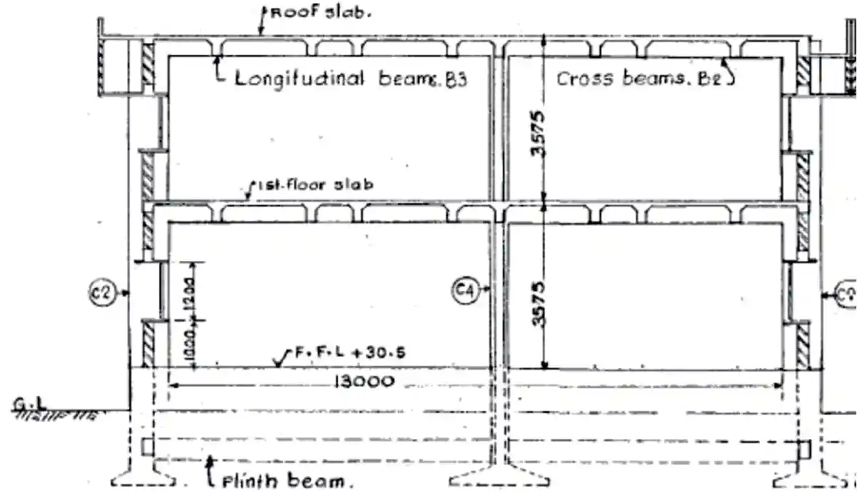 Figure 1a: Sectional details
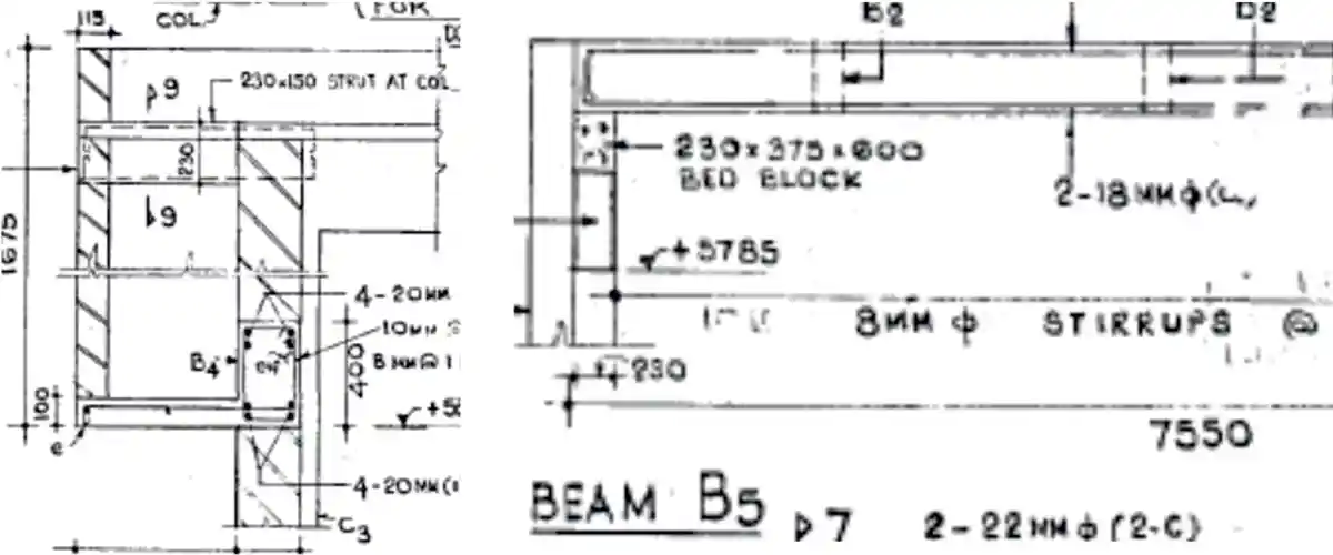 Figure 1b: Cross-section of floor beams and load-bearing masonry
Structural Layout of the Building
The building is an RCC framed construction with brick masonry infill. It is an H–shaped double-storeyed structure with parallel plan dimension of 72m x 13.6m and a connecting corridor. The height of each floor is 3.575m. Each arm of the building is structurally separated using expansion joints. Figure 1 shows the schematic representation of the section of building. From the sectional drawings, it is clear that the masonry and the reinforced columns (Fig.1a) were designed to share the floor loads. Geometrical details of beams, columns and slab are provided in table.1. The grade of concrete used was M20 and grade of steel Fe 415.
| Table 1 Sectional Properties of Beams, Columns, Slabs | |
| Member | Size |
| Longitudinal Floor Beams | 230mm x 600mm |
| Transverse Floor Beams | 150mm x 410mm |
| External Column | 150mm x 500mm |
| Internal Column (plus geometry) | 150 mm x 300 mm |
| Longitudinal Plinth Beams | 230mm x 300mm |
| Transverse Plinth Beams | 230mm x 450mm |
| Slab | 65mm thk |
Visual Inspection
Visual inspection generally is the primary method used as a first step in assessing the condition of the structure. An expert visual inspection of exposed concrete and masonry helps to detect and define areas of ageing-related distress that result in visible effects on the surface. To begin with, a team of experts inspected both the ground and the first floor of the building. The team evaluated the beams and slabs for explicit visual cracks and other distress in the structural members. During the visual inspection, a mandate on the non destructive tests required for precise evaluation of the structures, were also determined.
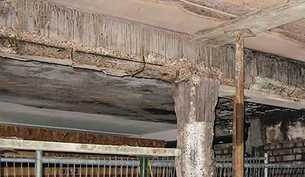
Though cracking was not visible at first except for in few columns in the southern block, close inspection revealed hairline cracks and also signs of repairs previously carried out in several columns. Except for the south block, plinth protection and drain covered the columns all around the periphery. The south block columns showed distress to a height of 0.8m, from the ground level. Organic soil was observed to cover this particular height of the column for quite some duration, and distress became visible on removing the soil cover (Figure 2). Roughcast plastered external masonry, though appeared intact cracking, was seen at the inner surface. There were spalls in sunshades and cracks in window panes too (Figure 3). There were no other evident signs of distress for internal beams, columns etc.
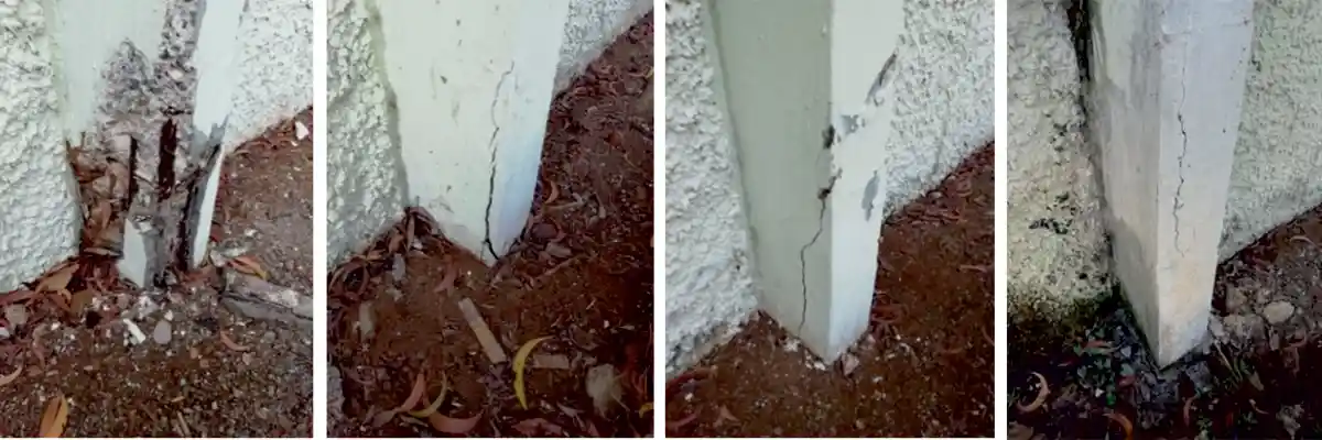 Figure 2: Spallation of columns
At the sites of distress, the spalled concrete was removed and tested for carbonation, pH and chloride penetration. The 6mm stirrups were corroded, while there was a reduction in diameter at the main bar of 22mm diameter. At one of the columns, the spalled concrete was showing biogenic growth at the inner surface. Hence the sample was tested using microbiological assays characterization. The topsoil which was covering the columns at the location of distress also was analysed in the lab. One of the columns was exposed up to foundation to check the condition below the ground. There was no distress found in the embedded columns and foundation. Water and soil samples were collected from the foundation and tested for sulphates, chlorides or any other harmful chemicals. Spalled, drilled concrete and cored samples were tested for chloride content and pH, further cover concrete removed for assessing the status for rebars. Rapid chloride penetration test was attempted to determine the permeability of concrete.
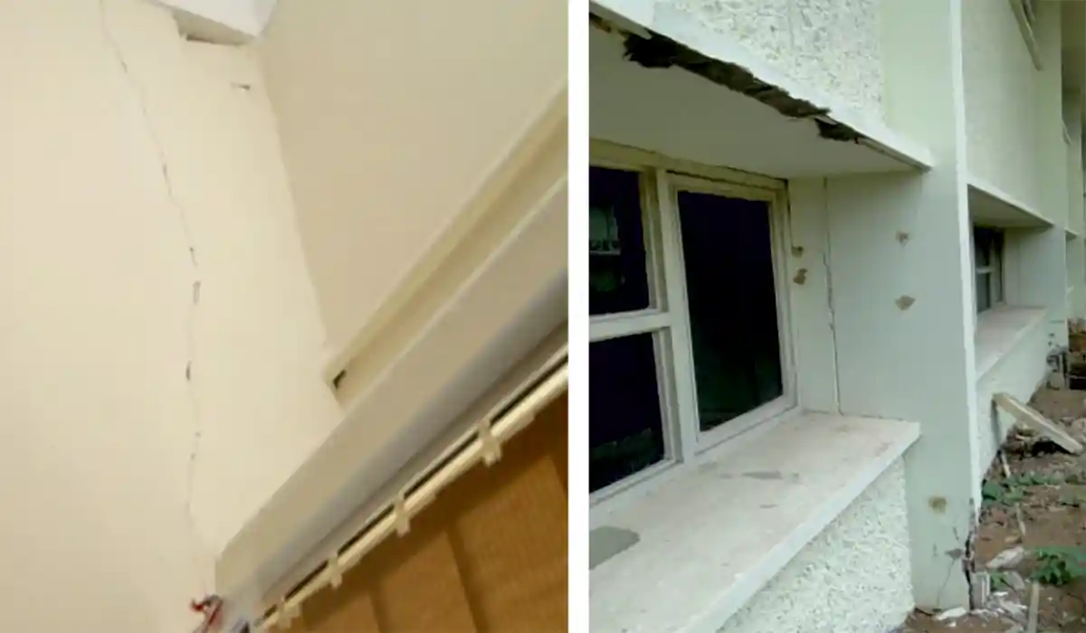 Figure 3: Cracks in masonry and sunshades
Planning
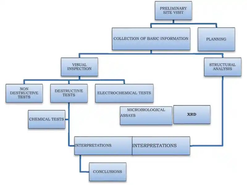 Figure 4: Flow chart of survey
| TABLE 2 Condition assessment methods | |
| Material and characteristic | Methods implemented for detection |
| Concrete/masonry | |
| General quality | Ultrasonic pulse velocity |
| Cracking/spalling | Visual inspection, Ultrasonic Pulse Velocity |
| Strength | Rebound Hammer Test, Ultrasonic Pulse Velocity |
| Microbiological assays | Microbially induced corrosion |
| Concrete Reinforcement | |
| Location of reinforcement | Rebar Locator |
| Corrosion | Visual Inspection, Electrical Resistivity |
| Concrete Durability | pH of concrete, Chloride content detection by titration, Carbonation test, RCPT |
| Microchemical analysis | XRD of concrete samples |
| Groundwater /soil quality | Chemical analysis, XRF analysis |
| Structural integrity/ stability | Total station readings |
Building is evaluated by modelling and analysis to check the structural capacity of the structure against gravity loading conditions such as dead and live loads. The structural analysis is done using an engineering software. The structure is idealized as a 3D frame, using line element for columns and beams. Figure 5 represents the model of the building for the analysis. The member forces have been calculated using limit state methods given in national code [3,4]. The dead load and live load as per code considered with a partial safety factor of one [5] (fig.6,7).
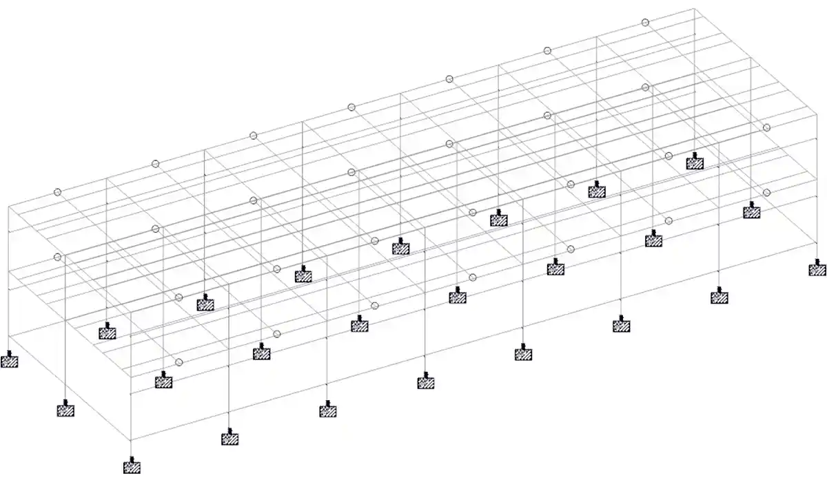 Figure 5: Skeletal structure of the building
The external columns were found to be sway columns with a slenderness ratio of 22, according to ACI318 [6]. Axial loads in the columns were exceeding the Euler critical load applying the stiffness variation in columns due to cracking, creep, and column non-linearity [fig.8]. Hence peripheral columns (150mm x 500mm) were failing due to instability and buckling.
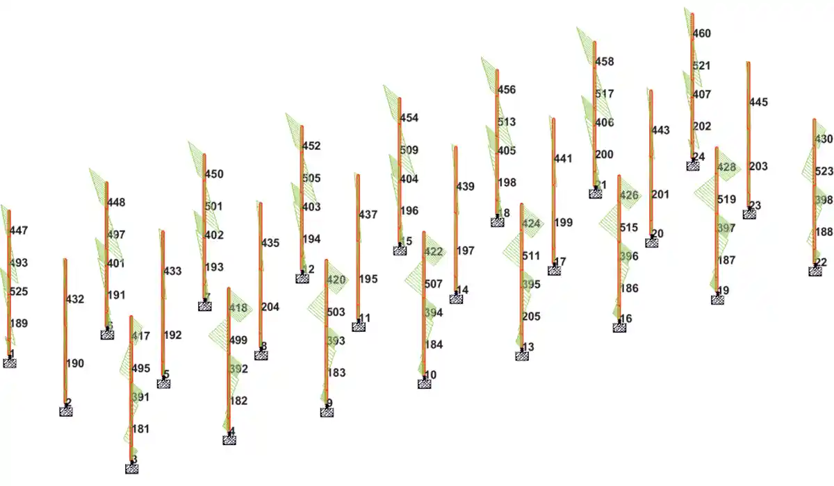 Figure 6: Column Bending Moment along the major axis due to static loads
Field Tests
Non-destructive tests of rebound hammer, ultrasonic pulse velocity, resistivity, were conducted around 26 locations in the building, such as external /internal columns and masonry.
Rebound Hammer Test
Schmidt rebound hammer is a simple, and handy tool, which can be used to provide a convenient and rapid indication of the compressive strength of concrete. When the plunger of rebound hammer is pressed against the surface of concrete, a spring-controlled mass with a constant energy is made to hit concrete surface to rebound back. The extent of rebound, which is a measure of surface hardness, is measured on a graduated scale. This measured value is designated as Rebound Number (rebound index). This is further converted to compressive strength of the material subjected to test. The rebound hammer testing was carried out as per IS-13311 (Part 2) [7] using Proceq make DIGI-SCHMIDT 2000 concrete test hammer of Model ND/LD. Around each point of observation, nine readings of rebound indices were taken and the average compressive strength was displayed for the point of observation.
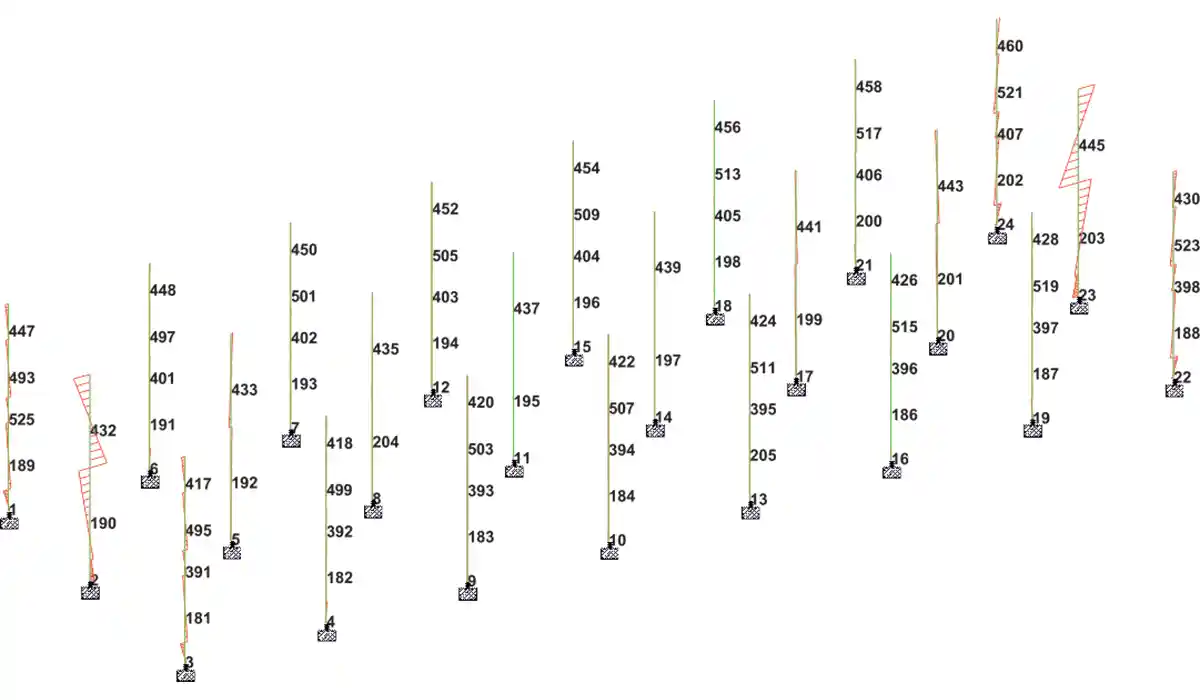 Figure 7: Column Bending Moment along minor due to static loads
Ultrasonic Pulse Velocity Test (UPV)
UPV test is used to measure the velocity of ultrasonic waves inside the concrete to establish the homogeneity and integrity of the concrete, the presence of cracks, voids and other imperfections and the quality of concrete in relation to standard requirement. Ultrasonic instrument used for testing was Proceq Tico ultrasonic instrument which is handy, battery operated and portable instrument. The electronic pulses are generated by the transmitting transducer and collected at the receiving transducer, and the travel time between the two transducers is measured electronically. Grids were made on the selected location, just opposite/adjacent as required to the selected location. The transducer was put on the selected grid on the location and the receiving transducer on the opposite/adjacent grid location after greasing the surface to prevent any air gaps between the testing surface and the transducers. General criterion for concrete quality grading is given in table 3[8].
| TABLE 3 Criterion for concrete quality grading as per IS 13311 (PART 1) | ||
| Sl.No. | Velocity criterion by cross probing(km/sec.) | Concrete quality grading |
| 1 | Above 4.5 | Excellent |
| 2 | 3.5 to 4.5 | Good |
| 3 | 3.0 to 3.5 | Medium |
| 4 | Below 3.0 | Doubtful |
The electrical resistivity is defined as the ratio between the applied potential and the current circulating between two electrodes providing the arrangement which enables the calculation of the geometrical characteristics. The electrical resistivity is an indirect measurement of the porosity and the connectivity of the pores. It is used to detect wet areas in the concrete and therefore is used to assess the probability or likelihood of corrosion of the reinforcement bar. One of the commercial equipment available for measurement of resistivity of concrete is, Resistivity Meter, which is a four probe device. This is based on the classical four electrode system in which four equally spaced electrodes are electrically connected to the concrete surface. Proceq make Resipod which is a fully integrated 4-point Wenner probe was used for testing[9].
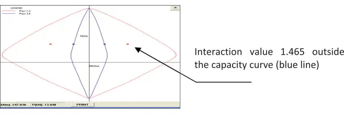 Figure 8: Interaction chart by using additional moment method
Laboratory Tests
Test for Chloride Content of Concrete
The presence of chloride in the concrete is the contributory factor towards corrosion of reinforcement. The chloride content of concrete can be determined by chemical analysis of concrete in the laboratory. The significance of this test is to understand the chloride content present in the concrete and also if different samples are obtained from different concrete depths, it can be established whether the chloride contamination was there in the original concrete or the same has come from the environment. The chloride content in concrete was determined from broken core samples of the concrete member, in accordance with IS: 14959 (part 2) [11]. As per IS 456, the maximum total Acid Soluble Chloride content for reinforced concrete or plain concrete containing embedded metal is 0.6 kg/m3. pH was determined using Hanna make HI991300 model portable pH meter.
| TABLE 4 Interpretation of resistivity results As per RILEM TC 154 | |
| Resistivity (ρ) range in kΩcm | Risk of Corrosion interpretation |
| < 10 | high |
| 10 to 50 | moderate |
| 50 to 100 | low |
| > 100 | negligible |
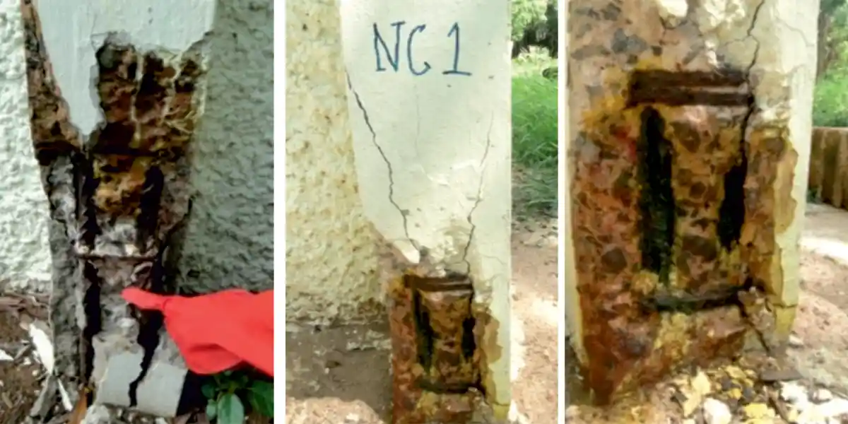 Figure 9: Colorimetric method to check free and bound chloride on the exposed structural member
In brief, the investigation was carried out at the fractured surfaces of the structure by spraying the Fluoresceine solution (1g/L in a 70% solution of ethyl alcohol in water) followed by Silver Nitrate (0.1mol/l) aqueous solution. A dark pink colouration indicated presence of free chloride areas and a dark brown colouration indicated bound chloride zone on the grey concrete (fig.9). This process was also adopted on a fractured core sample extracted from the structure, wherein the depth of free chloride penetration was indicated by a colour change with a clear demarcation till the region of bound chloride region.
Rapid Chloride Penetration Test
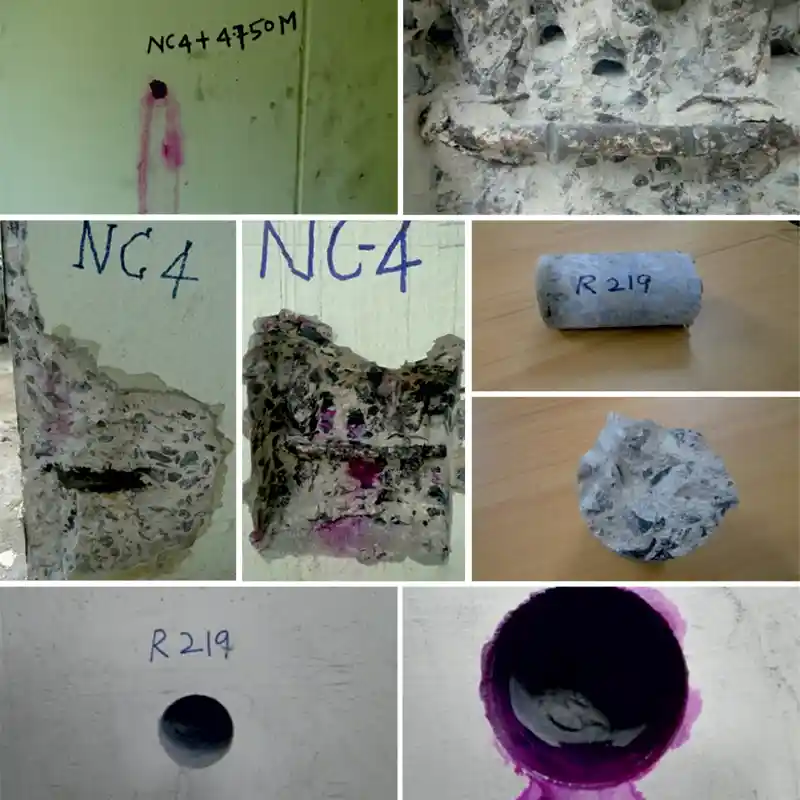 Figure 10: Concrete Carbonation tests on the fractured structural member, cored member and checking for corrosion of rebar
Carbonation
The carbonation test was carried out as per RILEM CPC-18[10]. The reduction of the pH value could be made visible by applying a 1% phenolphthalein solution to a freshly fractured surface of concrete. The non-carbonated areas turn red or purple while carbonated areas remain colourless. The phenolphthalein solution was sprayed on the freshly cored concrete surface and the colour change was observed (fig. 10).
Microbiological Assays
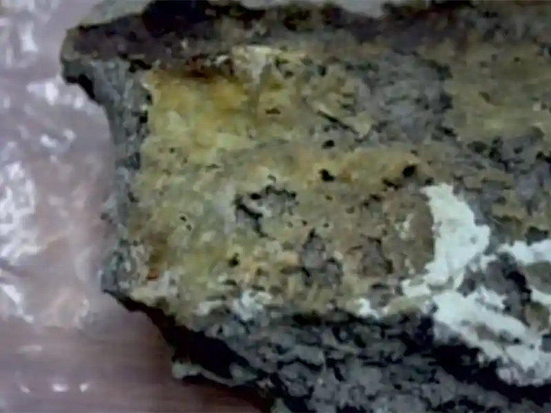 Figure 11: Biogenic growth at inner face of column
X-Ray Diffraction of Concrete Samples
XRD data were acquired on Intel make machine (Model - Equinox 2000) equipped with Gas Detection Cell (Argon and Ethan) detector and intensity measurements were carried out using germanium mono-chromated Cu-Ka radiation (l = 1.789 A0) in asymmetric acquisition mode. XRD involves directing an incident wave into a material and recording outgoing diffracted wave direction and intensity using a detector. Scattered waves emitted from an atom of different type and position, interface constructively or destructively along different paths. The crystal structure of a material is related to this diffraction pattern. By scanning, a sample in 2q range, all possible diffraction directions is obtained. The crystal phases of crushed concrete specimen were determined by correlating the change in intensity in the field of 10-80º of 2q. Crystalline phases identified from the standard database (JCPDS) and literature.
Results & Discussion
Non-Destructive Tests and Chemical Analysis
Rebound hammer and UPV were resorted to identify the condition of masonry, initially, at areas where there were no visible defects (table 5). With these readings as reference, the tests were conducted at areas were hairline cracks were visible in masonry. The range of UPV at good locations were 3450-4450m/s using the direct method and 2880-3220 m/s using the surface method. At regions were cracking was seen the UPV dipped to 2600m/s which shows degradation. The compressive strength obtained from rebound hammer, both for concrete columns /beams and masonry were in the range 35-45 N/mm2. The external columns were further tested after validating the healthiness inside the building. The columns showed reduced UPV values in the range of 2320m/s near the distress, 4700m/s at -0.9m from ground level, 4660&44600 at -0.6m and -0.3m levels. And above the distressed area also the UPV was as high as 4240m/s. These values prove that the distress is highly localized. The distressed area was dry hence half-cell potential measurements when tried gave only positive potentials.
| Table 5 Results of non-destructive tests | |||
| Sl.No. | Location | Rebound Hammer values (N/mm²) | UPV m/sec |
| 1 | C2 Column +0.6 m from Crack | 40 | 3820 |
| 2 | C3 Column +0.3 m from Crack | 40 | 4240 |
| 3 | C3 Column near Crack | 38.8 | 0-2320 |
| 4 | C3 Column-0.9m from Crack | 44.3 | 4700 |
| 5 | C3 Column- 0.6m from Crack | 39 | 4660 |
| 6 | C3 Column -0.3m from Crack | 43.3 | 4460 |
| TABLE 6 Chloride and sulphate in soil | |
| Ion | Concentration% |
| Chloride | 0.0055 |
| Sulfate | 0.0066 |
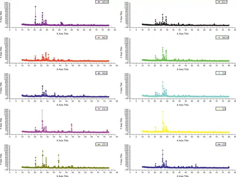 Figure 12: XRD results
Quartz phase from 20.85º, 26.65º, 36.54º, 39.46º, 50.14º, 60º and 68º were evident in some samples of external/internal columns, but not in all which shows some ageing. Calcium monosulphates (10.2º) and Friedel salt (11.05º) also appeared in some inner layers of samples [19-22]. The peaks at 13-14º indicate free chloride. Ettringite peaks at 23.5º were seen in the sample of C3 column, having biogenic growth.
| TABLE 7 Elemental composition in soil-XRF | ||
| S.No | Element | Concentration (%) |
| 1 | Al | 3.91 ±0.01 |
| 2 | Si | 24.17 ±0.12 |
| 3 | Ca | 3.06 ±0.18 |
| 4 | Fe | 3.26 ±0,12 |
While checking the capacity of the structure for un-factored static load combination peripheral columns (150mm x 500mm) were found to be failing by instability and buckling.
Non-destructive testing validates the visual inspections that the external columns are cracking just above the ground. Total station readings did not vary when monitored for around three months. Chemical analysis showed high chloride content (1.4kg/m3) in external concrete and 0.9 kg/m3 at internal columns. Thus, the source of chloride is assessed to be internal, that would have admixed during hydration (say CaCl2). Concrete core from an inner column showed evidence of bound chloride from chemical analysis and in XRD, which explained the absence of corrosion in the internal elements, even though total chloride content was exceeding the threshold value (of 0.6 kg/m3).
The grade of OPC cements used in the 1970s contained high C3A content of 10% [23,24], which explained the formation of Calcium chloroaluminate (Friedel salt). But XRD of spalled concrete from external columns were not showing Friedel salt peaks. The outer columns were heavily carbonated, and at high carbonation levels the Friedel salt is unstable hence breaks into free chloride which corrodes the rebars. Depth of carbonation was high at lower levels of external columns and no carbonation at inner columns. The reason for higher carbonation at the lower levels of column is the structural cracking and the conjugal higher permeability [25,26].
It can be inferred that, structural instability in the columns lead to the cracks, which further increased the carbonation, chloride diffusion, and even sulphate attack leading to corrosion of rebars, expansion, and spallation. From the above, the direct cause of failure could not be attributed to a single cause since many factors co-exist. These are interrelated. Carbonation, for example, may follow cracking due to sulphate attack or structural cracking or steel corrosion.
Holistically speaking, only external columns cracked due to local effects, and internal structural elements were healthy. Based on the level of structural degradation of columns for continuing the functional requirement as per the current national standards and deterioration of material property in steel and concrete, appropriate measure for retrofit has to be evolved.
| Table 8 Chloride content and pH of concrete | ||||
| Sl.No. | Sample No. | Average Chloride | Average pH | Carbonation |
| 1. | C2 +0.8 lvl | 1.239 | 8.955 | 40-50mm |
| 2. | C3 +0.8 lvl | 1.415 | 10.805 | 40-50mm |
| 3. | C7 +0.8 lvl | 1.365 | 10.115 | |
| 4. | C2 +4.75m | 0.885 | 10.4 | |
| 5. | C3 +4.75m | 1.504 | 11.58 | |
| 6. | C7 +4.75m | 1.482 | 10.87 | |
| 7. | NC1+0.8 lvl | 1.4891 | 10.29 | 20mm |
| 8. | NC4+0.8 lvl | 1.5147 | 11.46 | 20mm |
| 9. | NC12+0.8 lvl | 1.5051 | 11.6 | 15mm |
| 10. | NC16 0lvl | 0.4378 | 10.79 | 40mm |
| 11. | NC4 +1.75m | 0.806 | 0 | |
| 12. | NC4 +4.75m | 0.993 | 0 | |
| 13. | NC16 +4.75m | 0.25 | 0 | |
| 14. | NC16+1.75m | 1.613 | 2mm | |
| 15. | NC12+1.75m | 2.995 | 0mm | |
| 16. | Internal Beam 1 | 0.791 | 11.52 | 0mm |
| 17. | Internal beam 2 | 0.594 | 11.28 | 0mm |
Authors are obliged to the labs of WSCD, HSEG and XSCGS of Indira Gandhi Centre for Atomic Research for conducting tests for chloride, sulphates, microbiological assays, XRF and XRD which helped in the interpretation of the results.
References
- ACI 365.1R, Service life prediction.
- Corrosivity and durability map of India,M.Natesan et al ,CECRI,India.
- IS 456–Plain and reinforced code of practice
- SP 24: Explanatory Handbook on Indian Standard Code of Practice for Plain and Reinforced Concrete (IS
- 456:1978)”
- IS 875 Part –I & II-design loads (other than earthquake) for buildings and structures
- ACI 318 08 Building code requirement for structural concrete
- IS 13311 (Part 2):1992: Methods of Non–destructive testing of concrete: Part 2 Rebound Hammer.
- IS13311(Part 1):1992: Methods of Non–destructive testing of concrete: Part 1 Ultrasonic pulse velocity.
- Rilem Tc 154-E Electrochemical Techniques for measuring metallic corrosion
- RILEM CPC-18 - Measurement of hardened concrete carbonation depth
- IS14959 (Part 2):2001: Determination of water soluble and acid soluble chlorides in mortar and concrete –Method of test- Part 2: Hardened mortar and concrete.
- 2 Quick method to determine free and bound chlorides in concrete Mario Collepardi, 1st RILEM workshop on Chloride Penetration into Concrete,15-18 October 1995, St Rémy lès Chevreuse, France
- ASTM C1202 - 97 Standard Test Method for Electrical Indication of Concrete’s Ability to Resist Chloride Ion Penetration
- Report on reinforced concrete column failure, T. Subba Rao,WSCD,IGCAR dated 29th April2019.
- Report on chlorides and sulphates in soil, HSEG, IGCAR,2019.
- Report on XRD of concrete sample, XSCGS, IGCAR, 2019.
- Direct Determination of Phases in Portland Cements by Quantitative X-Ray Powder Diffraction, Paul Stutzman, NIST Technical note.
- Preparation of Needle-like Aragonite Precipitated Calcium Carbonate (PCC) from Dolomite by Carbonation Method, Chilakala Ramakrishna, Thriveni Thenepalli, Jae-Hoon Huh, and Ji Whan Ahn,†Journal of the Korean Ceramic Society, Vol. 53, No. 1, pp. 7~12, 2016
- Chloride ion binding behaviour of deicing slats under freeze-thaw environment, Hashimoto K et al., Second international conference of microstructural durability of concrete composites, April 2012, Amsterdam.
- Degradation of concrete buried in soil with saline groundwater, Yasushi Fujiwara, Tsuyoshi Maruya and Eiji Owaki, Nuclear Engineering and Design 138 (1992) 143-150
- Chloride binding related to hydration products Part I: Ordinary Portland Cement M.V.A. Florea, H.J.H. Brouwers Cement and Concrete Research 42 (2012) 282–290
- Mechanism of Friedel’s salt formation in cement rich in tri-calcium aluminate AK. Suryavanshi, J.D. Scantlebury, and S.B. Lyon. Cement and Concrete Research, Vol. 26, No. 5, pp. 717-727,1996
- Concrete technology, M.S. Shetty,1988.
- Quality control reports on chemical composition of cement, IGCAR,1970.
- Concrete deterioration in a 20-year-old structure in Kuwait. A. Qazweeni and O. K. Daoud, Cement and concrete research, Vol. 21, pp. 1155-1164, 1991
- Effect of carbonation on chloride penetration in concrete, Tatsuhiko Saeki, Third RILEM workshop on Testing and Modelling the Chloride Ingress into Concrete, 9-10 September 2002, Madrid, Spain
Published on:
19 April 2023
Published in: International Concrete Construction Technology, March - April 2023
Share:
We Value Your Comment