Diversion structures and check dams are constructed for diverting/ storing the water, flowing in shallow rivers/ streams for various purposes. The present practice is to use brick / stone / stone block masonry, for permanent check dams and sand bags / stone block, lined with wire crates for temporary or semi-permanent check dams. As a part of National Drinking Water Mission project, technique for construction of ferrocement check dams was developed at CSIR- Structural Engineering Research Centre, Ghaziabad/Roorkee (SERC) for smaller and medium heights. The technique includes the casting of precast ferrocement segments and then assembling these segments at the site using methods, developed at SERC(G). This technique saves construction time and cost to a greater extent.

P. C. Sharma, Retired Head, Material Sciences, CSIR-Structural Engineering Research Centre, Ghaziabad, Chief Editor, NBM&CW, New Delhi. Dr. Rajeev Goel, Senior Principal Scientist, CSIR-Central Road Research Institute, New Delhi.

Introduction

Mini check dams are constructed across small and shallow rivers/streams or water catchment areas for diverting water flow to the sources of collection / storage or for diverting water into mini-canals. These structures are needed in large numbers, especially in hilly areas where the volume of available rain water run-off is quite large and small check dams are often constructed as barrier for stopping and diverting rain water flow to surface / underground tanks for storage of sufficiently large quantity of water. Stone or brick masonry have been used for construction of these structures. Dry stone stacks, lined with wire mesh/ crating (Fig. 1), wooden logs and sand bags are other materials in use at present. These methods of construction are time consuming and need very large amount of construction materials posing handling problem, do not provide water-tight barriers, can get easily damaged, higher cost and need frequent repairs. Mini check dams are mostly constructed in interior / difficult areas where transportation of materials and manpower for construction and maintenance is very difficult.

Cross section of a dry masonary chek dam
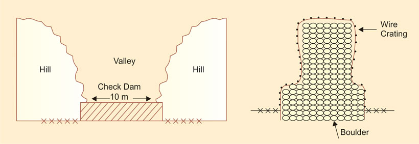
Figure 1: Cross section of a dry masonary chek dam at Ranichauri Tehri, Uttarakhand

To reduce the construction time, expenditure on maintenance and for providing leak-proof diversion structures, SERC(G) took the lead for development of mini check dams as part of National Drinking Water Mission, project of Government of India. Complete technology for construction of ferrocement mini check dams for heights upto 1.5m (suitable for shallow streams in hills and foothills) was developed at SERC(G) in 1986-87 and was demonstrated furing NDWM Training Programmes between 1988-92 period organised for Phed engineers, NGOs, and RES engineers in several states.

What is Ferrocement?

Cross section of a dry masonary chek dam
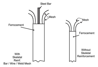
Figure 2: Ferrocement with or without skeletal reinforcement
Ferrocement is a durable long-lasting cement-based composite material. It is a modified form of reinforced cement mortar / micro-concrete, in which the reinforcement is finely subdivided and dispersed (Fig.2) in the matrix in order to achieve a closely spaced crack- free regime, coupled with excellent corrosion resistance and high impermeability to ingress in projects for irrigation, transportation, fishing, housing, storage, water supply, etc.

Apart from these, ferrocement has proved to be a very successful composite material for waterproofing, rehabilitation, and retrofitting of RCC and masonry structures.

Constituent of Ferrocement

The constituent of ferrocement are as follows: Cement, Sand, Water, Wire mesh, Admixtures, and Skeletal reinforcement

The cement used is normally Ordinary Portland Cement (33 or 43-grade). The well graded fine aggregate should comply with grading zone II of IS: 383-1970. Potable tap water (free from chlorine residue) is considered best for mixing mortar / micro-concrete, and curing. Steel wire meshes (Hot dip galvanized) are used to enhance the resistance to cracking, which is achieved due to the closely spaced small diameter reinforcement spread throughout the thickness and area of the ferrocement layer and high bond between reinforcement and matrix. Few selected admixtures such as pore sealants, bond improvers, and plasticizers are added to improve the workability, bond & strength, and water resisting properties. Skeletal reinforcement is used just to give the desired shape to ferrocement elements and for taking handling stresses.

The thickness of ferrocement elements generally varies from 10 to 50 mm whereas for water proofing rehabilitation & retrofitting applications, it varies from 16 to 50 mm depending upon type of structures and site specific requirements. In ferrocement construction, the minimum mesh reinforcement provided is 0.3% by volume. This may change depending upon the nature of the job. Two to six number of layers of hot dip annealed galvanized mesh reinforcement has been found adequate in most of the cases. Minimum cover to outermost layer of wire meshes is usually 4 to 5 mm which is enough due to the use of fine grain polymer modified matrix Square or Rectangular shape meshes performan better then Hexagonal meshes.

Details of Developed Technology
Precast Units


Precast Ferrocement Core Masonry Mould and Skeletal Reinforcement
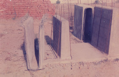
Figure 3: Precast Ferrocement Core Masonry Mould and Skeletal Reinforcement
The ferrocement core, which is the basic unit, is cast in inverted position over solid masonry moulds plastered in slope on both the sides. Slope is provided for facilitating the de-moulding of the cast units. Figure-3 shows a masonry mould, reinforcement cage and cast units. The mould surface is covered with a mixture of grease and diesel oil and a lightly oiled hessian cloth is placed over the mould for acting as a separation layer. The reinforcement cages are fabricated and then tied over the mould. The amount of reinforcement will depend on the size of the check dam and has to be properly designed. During the casting process, reinforcing bars and meshes are left projected on the top side and also on both ends of the long sides. The bars projected on the top of the inverted cast core are lapped to the base reinforcement and become an integral part of the RCC base. The size and reinforcement in the base will depend on the height of the dam and water force it has to face. The bars and wire mesh projecting on long side ends are used for jointing of one precast unit to other adjoining units on both sides. A minimum of two layers of hot-dip galvanised square woven mesh are provided on either side of the bar reinforcement (Fig.4.)

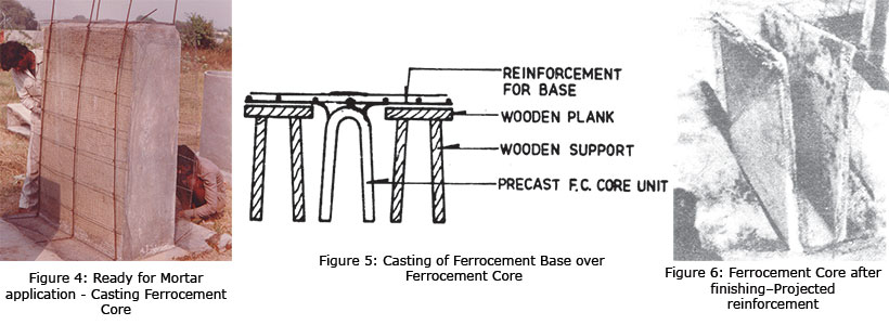
Mortar is applied by hand and compacted using an orbital vibrator, specially developed by author1. The cement sand mortar (or micro-concrete), used for casting, is designed to have a minimum compressive strength of 25 MPa at the age of 28 days. The cast unit is de-moulded after 24 hours period and then cured for next 24 hours. After a gap of 48 hours, the unit is lifted of the mould, inverted and the RCC base is cast (Fig.5). Segment unit with base is inverted after 36 hours of casting and inside is finished with cement: sand mortar using the same mix as used in the casting of core unit. A coat of cement slurry is applied before applying the finishing layer for improving bond with the precast surface. Figure-6 shows a finished segment.

Ferrocement Core

Jointing of precast segments

After attaining enough strength, sufficient to resist handling and transportation stresses, the segments are shifted to site. After the excavation for foundation as per design, the foundation concrete is laid and compacted.

The precast units are placed in position over the foundation concrete after laying of bed mortar. The laps for projecting reinforcement bars and meshes are fixed and tied with the reinforcement of the adjoining units (Fig.7, 8,9).

Fig. 7, 8,9

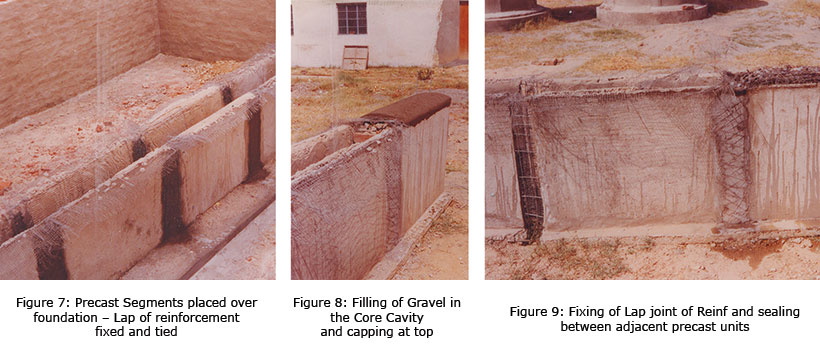
Mortar is then applied over the joints and compacted. After 24 hours, sand/soil or gravel is filled in the cavity of the segment upto the top level (Fig.8) and the reinforcement projected is bent and the top is sealed with mortar layer.

In case of soil filling, a layer of plastic sheet placed over soil surface helps in separating top Ferro cement layer from soil. In case, the gravel filling is used, plastic sheet is not necessary, as some part of mortar will enter into the gravel cavities and provide anchorage to the sealing layer. Joints and sealing layer is cured for at least 7 days. Figure-7,8,9 shows a cross-section of a Ferro cement assembled check dam.

The basic information about the system has been provided in this paper but the structure needs to be designed as per the site conditions and requirements.

Test on Prototype Structure and Requirements

Ferrocement Check Dam 6m long under test at SERC(G) 1988-92
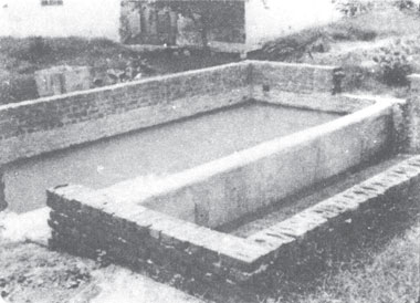
Figure 10: Ferrocement Check Dam 6m long under test at SERC(G) 1988-92
A prototype ferrocement check dam for 6.0 m span has been tested at SERC for a period of 36 months, during 1987-90 for evaluating the performance of joints and the structural system and for solving the difficulties/problems and for training techniques from NGOs which may come-up during such constructions. During the testing, the joints and the whole structure were found to be totally water tight. The overall performance was found satisfactory. The downstream of the test tank remained dry when the upstream was kept full of water (Fig.10).

The system developed at SERC(G) can be easily adopted for various other uses in hill road construction, soil conservation projects, and irrigation projects for providing support to soil.

Economics

Ferrocement check dams, developed at SERC, are cost-effective when compared with solid brickwork or stone masonry structures and save quantity of cement upto 20%. The saving in construction time can be upto 25%. Further, these can be constructed by local persons, just after one-day training. By this, employment is also generated at local level.

Use of Developed Technology for Construction of Mini Check Dams and River Training structures

Precast Ferrocement Check Dam Segment
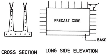
Figire 11: Precast Ferrocement Check Dam Segment
Using the developed technology, easy to handle, transport, and join ferrocement segments (Fig.11), can be cast and assembled at site for making the check dam structures. The length of these structures are generally upto 10-15m but in case of longer structures, intermediate solid supports could be provided for dividing the long structure into several spans.

Openings for discharging the excess water can also be provided by modifying the joint areas. Check dams are assembled using segment units of smaller lengths (1 to 1.5m), depending upon the load handling and transportation facilities.

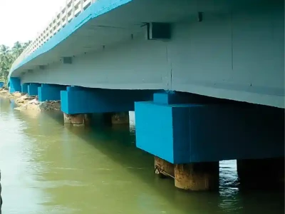
This developed technology is also found suitable for making guide bunds and diversion walls for bridges and river training works. Tests were carried out on both these types of structures from 1988 to 1992, and the results were very encouraging.

The dissemination of this technology was included in training programs-cum-demonstrations organised for National Drinking Water Mission in various states of the country for Public Health Engineering and Rural Development Department officials as well as for NGOs.

Special Vibration Device

A special vibration device was developed for thin ferrocement layers by author1 by modifying an orbital vibration device. This was successfully used for producing FC checkdams, segmental water tanks, Roof and walling units at SERC (G). If a ferrocement surface is vibrated during casting its strength, durability and service life is increased considerably.

Durability of Ferrocement Structures

Ferrocement is a highly durable composite construction material suitable for even producing Boats. There are examples when F.C. structures behaved and remained in use for many decades. InSharma India itself, F.C. water tanks constructed in 1974 are still in use. FC waterproofing treatment applied in 1976 is still intact. Some of the experimental structures produced during FC R&D work at SERC(G) (during 70-80) were in good shape till 2010 when these were dismantled to recover space. These included water tanks, grain bins, biogas holders, and a building using two leaf panel walls.

Acknowledgments

Financial support from National Technology Mission on Drinking Water is greatly acknowledged for funding this project which was carried out at SERC, Ghaziabad as a part of Drinking Water Mission project.

References
  • Sharma P.C. (1988), ‘Ferrocement structures for rain water harvesting schemes’, National seminar on issues of drinking water in hilly areas, Nainital, September.
  • Sharma P.C. (1999), ‘Construction techniques, casting, installation and maintenance of ferrocement products’, Keynote lecture in workshop on Ferrocement for Housing Development, February, The Institution of Engineers (India), Nagpur.
  • Sharma P.C. (1990), ‘Rain water harvesting techniques for drinking purposes’, Lecture Notes published for National Drinking Water Mission – Department of Rural Development, Government of India, March.
  • Sharma P.C. (1991), ‘Construction techniques, casting, installation and maintenance, Proceedings of Ferrocement Training Course at AuroviIle Building Centre, AuroviIle (Tamil Nadu), February.
  • Status Report on CSIR Programmes for National Drinking Water Mission - Published by CSIR, New Delhi.
  • Sharma P.C. (2013), ‘Construction and repair techniques for ferrocement applications’, Proceedings of International conference on Trends and Challenges in Concrete Structures’, Ghaziabad, December, pp.658-676.
Concrete Rheology - Unveiling the Secrets of Concrete
Concrete is a heterogeneous composite complex material, and its hardened property is influenced by its fresh property. Concrete today has transformed into an advanced type with new and innovative ingredients added - either singly or in

Read more ...

ICRETE: Making Concrete Economical
ICRETE offers many benefits apart from reducing cement content and giving high grades saving to ready-mix concrete companies; it helps reduce shrinkage and permeability in concrete slabs, increases the durability of concrete, and also works

Read more ...

UltraTech Cement to implement Coolbrook’s RotoDynamic HeaterTM revolutionary technology for industrial electrification
UltraTech Cement Limited, India’s largest cement and ready-mix concrete (RMC) company, and Coolbrook, a transformational technology and engineering company, will jointly develop a project to implement Coolbrook’s RotoDynamic HeaterTM (RDH)

Read more ...

Plastic Shrinkage and Cracks in Concrete
Plastic shrinkage cracking occurs when fresh concrete is subjected to a very rapid loss of moisture. It is caused by a combination of factors such as air and concrete temperature, relative humidity, and wind velocity at the surface of concrete. These can cause

Read more ...

Mechanised way of plastering with spray Plaster Machine
This paper covers the research work carried out on cement plastering process for internal and external building wall by using spray plastering machine. Objective of study is to experiment and compare the plastering activity by conventional way and

Read more ...

Construction Defects Investigation & Remedies
In recent years, the speed of construction has increased very fast; buildings which used to take 3-5 years are now getting completed in 1-2 years. There is a race to complete projects faster, but due to this speedy construction, the quality of construction is often

Read more ...

Challenges in usage of Hydrogen in Cement Industry
With its zero-emission characteristics, hydrogen has become a promising decarbonization path for the cement industry. While there are several issues that need to be resolved in the use of hydrogen, there are also many advantages, so much so that the growth

Read more ...

Enhancing Corrosion Resistance of Steel Bars in Reinforced Concrete Structures
Reinforced concrete is a composite material which is made using concrete and steel bars. Concrete takes the compressive forces and steel bar takes tensile forces. Concrete around the steel bar protects it from corrosion by providing an alkaline environment

Read more ...

Moving toward workability retention to rheology retention with low viscosity concrete technology
Amol Patil, Sr. Specialist - General Manager (Admixture and Specialty Products), Master Builders Solutions (India), and Nilotpol KAR, Managing Director, Master Builders Solutions (South Asia), present a paper on the concept of low viscosity concrete in

Read more ...

Cement industry innovating eco-friendly packaging
Cement companies are constantly innovating to meet global sustainability standards and improve logistics, shelf life, and utility of cement, while reducing wastage. Thei aim is to reduce their environmental impact without compromising their product

Read more ...

IIT Madras uses Solar Thermal Energy to Recycle Waste concrete
Researchers at the Indian Institute of Technology Madras have developed a treatment process using solar thermal energy to recycle construction and demolition debris. Waste concrete from demolition was heated using solar radiation to produce recycled concrete

Read more ...

Textile Reinforced Concrete - A Novel Construction Material of the Future
As a new-age innovative building material, TRC is especially suited for maintenance of existing structures, for manufacturing new lightweight precast members, or as a secondary building material to aid the main building material. Textile Reinforced Concrete

Read more ...

Technological Innovation for Use of Bottom Ash by-product of Thermal Power Plants in the Production of Concrete
The day is not far for the adoption of this innovative, eco-friendly, and cost-effective bottom ash – concrete process technology by construction agencies undertaking road/infrastructure project works, real estate developers, ready mix concrete (RMC) operators

Read more ...

Headed Bars in Concrete Construction
Using headed bars instead of hooked bars offer several advantages like requirement of reduced development length, less congestion, ease of transport and fixing at site, better concrete consolidation, and better performance under seismic loads.

Read more ...

Sustainability of Cement Concrete - Research Experience at CRRI on Sustainability of Concrete from Materials Perspective
It can be said that ever since the publication of the document of World Commission on Environment and Development [1], the focus of the world has diverted towards sustainability. Gro Harlem Bruntland [1] defined sustainable development as “development

Read more ...

Shrinkage, Creep, Crack-Width, Deflection in Concrete
The effects of shrinkage, creep, crack-width, and deflection in concrete are often ignored by designers while designing structural members. These effects, if not considered in some special cases such as long span slabs or long cantilevers, may become very

Read more ...

Concrete Relief Shelve Walls - An Innovative Method of Earth Retention
Relief shelve walls are a unique concept that use only conventional construction materials like PCC / RCC / steel reinforcements, and work on a completely different fundamental to resist the lateral load caused due to soil. Information on the various dimensions

Read more ...

Carbon Neutrality in Cement Industry A Global Perspective
Increasing energy costs, overcapacity, and environmental pollution are the top concerns of the cement industry, which is one of the major contributors to CO2 emissions. Dr S B Hegde, Professor, Department of Civil Engineering, Jain College of Engineering

Read more ...

Finnish company Betolar expands to Indian concrete markets with a cement-free concrete solution
Betolar, a Finnish start-up, and innovator of geopolymer concrete solution Geoprime®, has expanded its operations to Europe and Asian markets including India, Vietnam and Indonesia. Betolar’s innovation Geoprime® is the next-generation, low carbon

Read more ...

Why Fly Ash Bricks Are Better Than Clay/Red Bricks
It is estimated that in India each million clay bricks consume about 200 tons of coal and emit around 270 tons of CO2; on the other hand, with fly ash bricks production in an energy-free route, there are no emissions. Dr. N. Subramanian, Consulting

Read more ...