Application of Ultra-Sonic Pulse Velocity Techniques for Concrete Quality Measurements
Uday Bhise, Engineer. NDT; Durocrete Engineering Services Pvt. Ltd.
Introduction
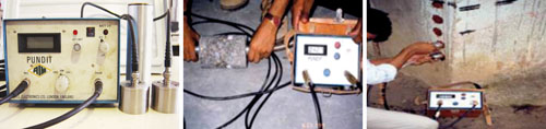
This method of testing was originally developed for use on concrete and the published accounts of its application are concerned predominately with this material. A considerable volume of literature has been published describing the results of research on the use of ultrasonic testing for concrete and for fuller details of this application the reader is referred to the Bibliography in the end of this paper. In Britain, the method was first developed by Jones and Gatfield at the Road Research Laboratory between 1945 and 1949 and also independently in Canada by Leslie and Cheesman at about the same time. The apparatus developed at that time made use of a cathode-ray oscilloscope for the measurement of transit times and modified forms of this equipment have been widely used in many countries. The equipment was particularly useful in the laboratory but was less easy to use under field conditions. Today’s various nondestructive testing equipment have been designed particularly for field testing being light, portable and simple to use. They can be operated independently of the mains power supply when used in the field and directly from the ac mains supply for laboratory use.Ultrasonic testing is now widely used throughout the world and it is clear that the advantages of this method over traditional methods of testing are likely to increase further its application. In particular, its ability to examine the state of concrete in depth is undoubtedly very good.
Applications for Pulse Velocity Testing
The velocity of ultrasonic pulses traveling in a solid material depends on the density and elastic properties of that material. The quality of some materials is sometimes related to their elastic stiffness so that measurement of ultrasonic pulse velocity in such materials can often be used to indicate their quality as well as to determine their elastic properties. Materials which can be assessed in this way include, in particular, concrete and timber but exclude metals. When ultrasonic testing is applied to metals its object is to detect internal flaws which send echoes back in the direction of the incident beam and these are picked up by a receiving transducer. The measurement of the time taken for the pulse to travel from a surface to a flaw and back again enables the position of the flaw to be located. Such a technique cannot be applied to heterogeneous materials like concrete or timber since echoes are generated at the numerous boundaries of the different phases within these materials resulting in a general scattering of pulse energy in all directions.The pulse velocity method has been shown to provide a reliable means of estimating the strength of timber and has been used to test various kinds of timber products. It is in use for the detection of rot in telegraph poles and provides a very economic method of inspecting these poles while in service. The same equipment can be used to test rock strata and to provide useful data for geological survey work. The method has also been used for testing graphite and it is likely that it will prove useful for testing other non-metallic materials.
Velocity of Longitudinal Pulses in Elastic Solids
It can be shown that the velocity of a pulse of longitudinal ultrasonic vibrations traveling in an elastic solid is given by:V = E(1 - ν) / ( ρ(1 + ν)(1 - 2ν) )
Where E is the dynamic elastic modulus
where ρ is the density
where ν is Poisson’s ratio.
| Table 1 | ||
| Sr. No. | Material | Frequencies |
| 1 | Concrete | 24-150kHz |
| 2 | Timber | 150-220kHz |
| 3 | Graphite | 200kHz & upwards |
| 4 | Cast Iron | 1MHz |
| 5 | Ceramics | 24-220kHz |
Applications for Concrete
The pulse velocity method of testing may be applied to the testing of plain, reinforced and pre-stressed concrete whether it is pre-cast or cast in situ. The measurement of pulse velocity may be used to determine:- The homogeneity of the concrete
- The presence of voids, cracks or other imperfections
- Changes in the concrete which may occur with time (i.e. due to the cement hydration) or through the action of fire, frost or chemical attack
- The quality of the concrete in relation to specified standard requirements, which generally refer to its strength.
| Sr. No. | Velocity Range | Concrete Quality |
| 1 | Below 3.0 Km./Sec. | Poor |
| 2 | 3.0 – 3.5 Km./Sec. | Medium |
| 3 | 3.5 - 4.5 Km./Sec. | Good |
| 4 | 4.5 Km./Sec.& above | Excellent |
Quality of concrete can be assessed in terms of uniformity, incidence or absence of internal flaws etc., in turn indicative of the level workmanship employed. Internal flows & cracks can also be assessed using the pulse velocity techniques. The values of pulse velocities obtained, depend upon number of factors, any single criteria for assessing the concrete only on the basis of pulse velocity given in above table can be held to a satisfactory to a general extent.
Accuracy
In most of the applications, it is necessary to measure the pulse velocity to high degree of accuracy since relatively small changes in pulse velocity usually reflect relatively large changes in the condition of the concrete. For this reason, it is important that care be taken to obtain the highest possible accuracy of both the transit time and the path length measurements since the pulse velocity measurement depends on both of these. It is desirable to measure pulse velocity to within an accuracy of ±2% which allows a tolerance in the separate measurements of path length and transit time of only a little more than ±1%. When such accuracy of path length measurement is difficult or impossible, an estimate of the limits of accuracy of the actual measurements should be recorded with the results so that the reliability of the pulse velocity measurements can be assessed.Coupling the Transducers with the Concrete Surface
Accuracy of transit time measurement can only be assured if good acoustic coupling between the transducer face and the concrete surface can be achieved. For a concrete surface formed by casting against steel or smooth timber shuttering, good coupling can readily be obtained if the surface is free from dust and grit and covered with a light or medium grease or other suitable couplant. A wet surface presents no problem. If the surface is moderately rough, stiffer grease should be used but very rough surfaces require more elaborate preparation. In such cases the surface should be ground flat over an area large enough to accommodate the transducer face or this area may be filled to a level smooth surface with a minimum thickness of a suitable material such as plaster of Paris, cement mortar or epoxy resin, a suitable time being allowed to elapse for the filling material to harden. If the value of the transit time displayed remains constant to within ±1% when the transducers are applied and reapplied to the concrete surface, it is a good indication that satisfactory coupling has been achieved.Concrete Testing Transducer Arrangement
The diagrams above show three alternative arrangements for the transducers when testing concrete. Whenever possible, the direct transmission arrangement should be used. This will give maximum sensitivity and provide a well defined path length. It is, however, sometimes required to examine the concrete by using diagonal paths and semi-direct arrangements are suitable for these.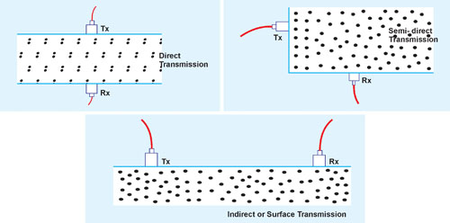
The indirect arrangement is the least satisfactory because, apart from its relative insensitivity, it gives pulse velocity measurements which are usually influenced by the concrete layer near the surface and this layer may not be representative of the concrete in deeper layers. Further more the length of the path is less well defined and it is not satisfactory to take this as the distance from centre to centre of the transducers. Instead, the method shown below should be adopted to determine the effective path length.
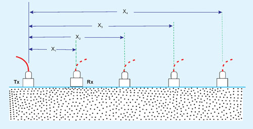
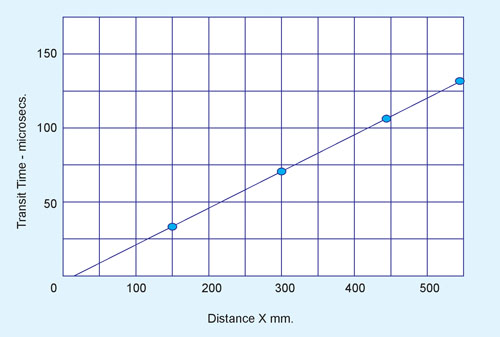
In this method, the transmitting transducer is placed on a suitable point on the surface and the receiving transducer is placed on the surface at successive positions along a line and the centre to centre distance is plotted against the transit time. The reciprocal of slope of the trend line plotted through these points gives the mean pulse velocity at the surface as illustrated below.
In general, it will be found that the pulse velocity determined by the indirect method of testing will be lower than that using the direct method. If it is possible to employ both methods of measurement then a relationship may be established between them and a correction factor derived. When it is not possible to use the direct method an approximate value for VD may be obtained as follows:
VD. ~ 1.05V1
Where VD is the pulse velocity obtained using the direct method.
V1 is the pulse velocity obtained using the indirect method.
If the points do not lie in a straight line, it is an indication either that the concrete near the surface is of variable quality or that a crack exists in the concrete within the line of the test position.
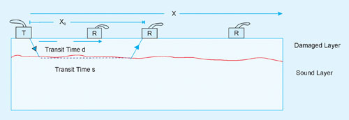
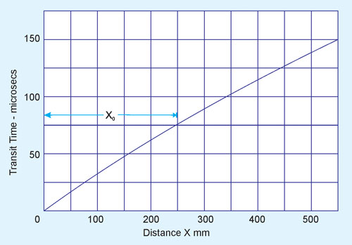
A change of slope (as shown above) in the plot could indicate that the pulse velocity near the surface is much lower than it is deeper down in the concrete. This layer of inferior quality could arise as a result of damage by fire, frost, sulphate attack, etc. For transducer separation distances up to Xo to the pulse travels through the affected surface layer and the slope of the line gives the pulse velocity in this layer. Beyond Xo the pulse has travelled along the surface of the underlying sound concrete and the slope of the line beyond Xo gives the higher velocity in the sound concrete.
The thickness of the affected surface layer may be estimated as follows:
t = ( Xo/2 ) ( (Vs - Vd) / (Vs + Vd) )
Vd is the pulse velocity in the damaged concrete (in km/s)
Vs is the pulse velocity in the underlying sound concrete (in km/s)
t is the thickness of the layer of damaged concrete (in mm)
Xo is the distance at which the change of slope occurs (in mm).
Influence of Test Conditions
The pulse velocity in concrete may be influenced by any or all of the following:- Path length
- Lateral dimensions of the specimen tested
- Presence of reinforcing steel
- Moisture content of the concrete
Pulse velocity will not be influenced by the shape of the specimen provided its least lateral dimension (i.e. its dimension measured at right angles to the pulse path) is not less than the wavelength of the pulse vibrations. For pulses of 50 kHz frequency, this corresponds to a least lateral dimension of about 80mm. Otherwise, the pulse velocity may be reduced and the results of pulse velocity measurements should be used with caution. The temperature of the concrete has been found to have no significant effect on pulse velocity over the range from 5° to 30°C. So that except far abnormally extreme temperatures.
Pulse Velocity in Steel Bar
The velocity of pulses in a steel bar is generally higher than they are in concrete. For this reason, pulse velocity measurements made in the vicinity of reinforcing steel may be high and not representative of the concrete since the ultra sonic equipment indicates the time for the first pulse to reach the receiving transducer. The influence of the reinforcement is generally very small if the bars run in a direction at right angles to the pulse path and the quantity of steel is small in relation to the path length. It is however preferable to avoid such a path arrangement and to choose a path which is not in a direct line with the bar diameters. When the steel bars lie in a direction parallel to the pulse path, the influence of the steel may be more difficult to avoid as can be seen. It is, however, not easy to make reliable corre- ctions for the influence of the steel.Pulse Velocity in Moist Concrete
The moisture content of concrete can have a small but significant influence on the pulse velocity. In general, the velocity is increased with increased moisture content, the influence being more marked for lower quality concrete. The pulse velocity of saturated concrete may be up to 2% higher than that in dry concrete of the same composition and quality, although this figure is likely to be lower for high strength concrete.Conclusions
- The ultrasonic principle is the best principle to study the homogeneity of the concrete.
- The best method to interpret the concrete quality by ultrasonic technique is the direct method to have better clarity of homogeneity in the heart of concrete.
- Some of the ultrasonic applications stated above need to ascertain by the actual use in the field by the expert ultrasonic technician under the guidance of an expert civil engineer.
- The effect on the pulse velocity due to present of steel is not very significant if the bars are running perpendicular to the pulse path. The further effect of steel running parallel to the pulse path need to be studied in detail & accordingly the correction factors are need to be developed.
- When pulse velocity measurements are made on concrete as a quality check, a contractor may be encouraged to keep the concrete wet for as long as possible in order to achieve an enhanced value of pulse velocity. This is generally an advantage since it provides an incentive for good curing practice.
Bibliography
- Properties of concrete By Neville.
- I.S.13311(Part-1)-1992 : ultra sonic pulse velocity method of testing the concrete
- Durocrete Engineering Services Pvt. Ltd. Various reports & research on NDT.
- Research into the correlation between concrete strength and UPV values By P. Turgut Harran University, Engineering Faculty, Civil Engineering Department Osmanbey Campus, 63000, Sanliurfa, Turkey.
- Overview of Nondestructive Evaluation Projects and Initiative at NSF By Chong, K. P., Scalzi, J. B., and Dillon, O. W., "Journal of Intelligent Materials, System and Structures, Vol. 1, pp. 422-431, October 1990.
Published on:
08 June 2011
Published in: NBM&CW June 2011
Share:
We Value Your Comment