Structural Behaviour of High Performance Fiber Reinforced Concrete Beam Column Joints Under Cyclic Loading
Rajesh Kumar Sharma, Research Scholar and H K Sharma, Professor, Department of Civil Engineering, National Institute of Technology, Kurukshetra
Introduction
The main reasons in a joint shear failure, are in-adequate transverse reinforcement in the beam-column joint region and strong beam / weak column design. At the same time, detailing of reinforcement in beam-column joints affects the strength and ductility of structures. It has been identified that insufficient seismic performance in the reinforced concrete (RC) structures built with low strength concrete or insufficient reinforcement and improper reinforcement detailing, resulting
in non-ductile performance of moment resisting frames, lead to brittle failure of the members in a devastating manner. These types of local failures can cause global failure of mechanism required in seismic upgrading of deficient structures.
It has been observed that conventional concrete loses its tensile resistance when multiple cracks develop in a structure. However, to sustain a portion of its resistance following cracking to resist more cycles of loading, fibrous concrete can be used to make it more sustainable. In the structural integrity of the building, beam-column and beam-column-slab structural systems play an important role and therefore they have to be provided with adequate strength and stiffness to sustain the load transmitted from beam or column. Transverse reinforcement in the form of closely spaced hoops was recommended in the ACI-ASCE Committee 352 report [ACI-2002] (1). However, casting of beam-column joints become difficult due to congestion of reinforcement which may lead to honeycombing in concrete [Kumar et-al, 1991] (2).
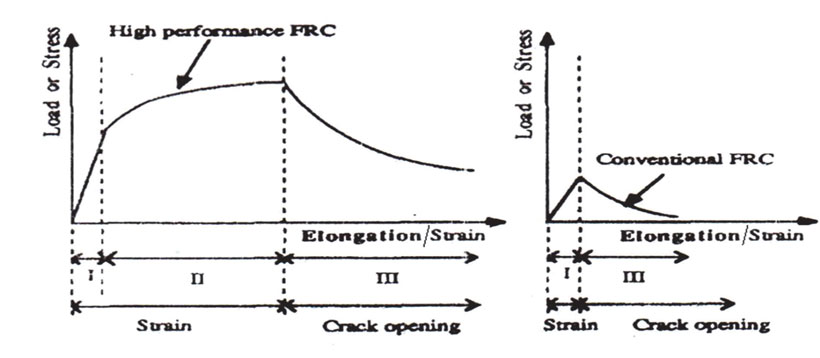
Figure 1: Stress-strain behaviour of cementitious matrices [Naaman et-al., 1991] (3)
High Performance implies an optimized combination of structural properties such as strength, toughness, energy absorption, stiffness, durability, multiple cracking and corrosion resistance taking into account the final cost of the material and above all, the produce manufactured. High performance fiber reinforced concrete (HPFRC) is defined by an ultimate strength higher than their first cracking strength and the formation of multiple cracking during inelastic deformation process. High performance is meant to distinguish structural material from the conventional one, as well as to optimize a combination of properties in terms of final application in real civil engineering structures, Figure 1. High performance concrete (HPC) can be designed to give optimized performance characteristics for a given set of usage and chemical admixtures like silica fume and super-plasticizer to enhance the strength, durability and workability qualities to a very high extent and can be designed to give optimized performance characteristics for a given set of load, usage and exposure conditions consistent with the requirements of cost, service life and durability.
The objectives of present study are to develop HPFRC of higher strength and performance, and to utilize such HPFRC in beam-column joint region, in an attempt to replace transverse reinforcement at an optimum fiber content, type and aspect ratio.
The critical review of existing literature reveals that various studies were conducted to investigate behaviour of beam-column joints with normal strength concrete. Jiuru et al. (4) studied effect of fibers on the beam-column joints and developed equations for predicting shear strength of joints for normal strength concrete. Singh and Kaushik (5) investigated behaviour of fiber reinforced concrete corners under opening bending moments. These investigations indicated that because of low fiber volume percentage, there is only a noticeable gain in efficiency with increase in fiber volume fraction up to a certain limit beyond which there is a drop in mix workability and joint efficiency. Thirugnanam et al. (6) investigated experimentally effect of using SIFCON in the hinging zones of multistoried frames subjected to cyclic loading. It was concluded that the use of SIFCON in the hinging zones increases first crack load and ductility by 40 &100 percent, respectively. The energy absorption capacity was also increased by 50 percent by adopting SIFCON in the selected fuse locations of R C structures. Bayasi and Gevman (7) also experimentally proved the confinement effects of fibers in the joint region, and a reduction in the lateral reinforcement by using fiber concrete. Bakir (8) conducted extensive research on parameters that influence behavior of cyclically loaded joints and derived equations for calculating shear strength of the joints. Ganeshan et al. (9) described the experimental results of ten steel fiber reinforced high performance concrete (SFRHPC) exterior beam-column joints under cyclic loading. Test results indicated that the provision of steel fiber reinforced high performance concrete (SFRHPC) in beam column joints enhances strength, ductility and stiffness, and is one of the possible alternative solutions for reducing the congestion of transverse reinforcement in beam-column joints.
Several researchers (10-13) also studied beam-column connections subjected to opening bending moments. It was found that in all the RC specimens, the joints failed before reaching the capacity of the connecting members. There was significant difference in different joint’s efficiency due to variety of reinforcement details. Based on the comparison of observed responses, it was found that the addition of 1.5 percent steel fibers were effective in reducing amount of steel bars in the beam–column joints of railway bridges.
The review of published literature illustrated that most of the studies are limited to normal strength concrete and research in the area of high performance concrete beam-column joint is limited. Previously, most of the studies were limited to normal strength concrete and research in the area of high performance concrete beam-column joints is almost non-existent/limited. Further, it is observed that earlier researchers used SFRC in the beam-column joints and fiber volume content
(Vf) was redistricted to 2 percent by volume. The mechanism for improved tensile strain capacity of discontinuous fiber composites was absent in their concept. Since vulnerable locations like beam-column joints are subjected to high horizontal and vertical forces, HPFRC was developed and utilized to investigate the structural performance of beam-column joints.
Experimental Investigation
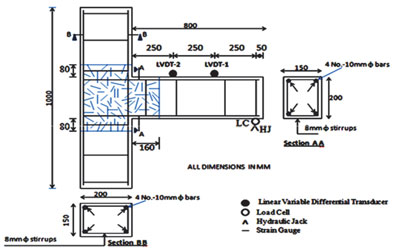
Figure 2: Experimental setup and position of steel fiber in a typical beam-column specimen
| Table 1: Composition of HPC Mix | |||||||
| Cement (kg/m3) | Silica Fume (kg/m3) | Fine Aggregate (kg/m3) | Coarse Aggregate (kg/m3) | Super- Plasticizer (kg/m3) | Steel Fiber (%) | Water (Kg/m3) | Water Cement Ratio |
| 492 | 123 | 615 | 984 | 4.90 | 0 | 154 | 0.25 |
The steel fibers corresponding to 6, 8, 9 and 10 percent were added to HPC to achieve HPFRC, keeping all other constituents same as those for HPC. The proportioning of various constituents of HPC was based on ACI method, conforming to Table 2.
| Table 2: Typical Range of HPC Mix Composition (14) | |
| Constituent | Typical Range (kg/m3) |
| Powder | 400-750 |
| Water | 150-210 |
| Coarse Aggregate | 750-1000 |
| Fine Aggregate | 360-550 |
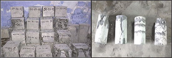
Figure 3 illustrates typical view of tested specimens of crimped and straight steel fibers based control HPFRC cubes and cylinders of size 150 mm, 300 x 150 mm respectively. These controlled specimens were tested to obtain compressive, split tensile and flexural strengths, at ages of 28 days respectively.
Exterior Beam-Column Joint Specimens
For casting exterior beam column joint specimens, water proof shuttering grade ply-wood moulds were used. Reinforcement cages were fabricated with nominal reinforcement using 10 mm dia Fe 500 grade bars as main reinforcement in beam and column where as 8 mm dia bars were used for shear stirrups. Required quantity of cement, silica fume, fine and coarse aggregate were mixed thoroughly in a drum type concrete mixture in which 50% of water was added to the dry mix. The remaining 50% water was mixed with super-plasticizer and these constituents are mixed till a uniform mixture is obtained. After 24 hours these specimens were demolded and cured for 28 days. The specimens were allowed to become dry after 28 days for some time and painted before testing, Figure 4. A special steel loading frame of 600 kN load capacity was used to test these specimens. A constant cyclic load was applied through hydraulic jack of 100 kN capacity with 5 kN incremental loading.
 |
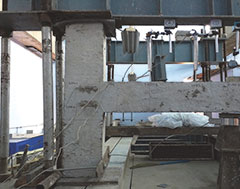 |
| Figure 3: Tested specimens | Figure 4: Beam-column joint specimen during testing |
Analysis of Results and Discussion
Seventeen nos. beam-column joint specimens, cast as per the procedure discussed earlier were tested under 600kN capacity loading frame under cyclic loading. These specimens were designated as per nomenclature mentioned in Table 3 for different type of fibers (straight and crimped), aspect ratio and fiber contents (0, 6, 8, 9 and 10 percent) by volume respectively. These specimens were tested to investigate the compressive, tensile and flexural strength of HPC & HPFRC at 28 days. Table 3 illustrates compressive, tensile and flexural strength of HPFRCcontrol specimens. It can be seen that the compressive strength increases significantly by increasing the fiber content from 6 to 9 percent. Further in most cases there is decrease in strength from 9 to 10 percent fiber volume contents. In comparison to Non Fibrous Concrete (NFC), it is increasing for SF 40/6, SF 40/8, SF 40/9, ZZ 50/6, ZZ 50/8 & ZZ50/9 and further decreasing for SF 40/10, SF 50/10, ZZ 40/10 & ZZ 50/10. The compressive, split tensile and flexural strengths for the specimen containing crimped fibers volume of 9 percent with k= 80 was found to be maximum values 72.0, 20.96 and 16.85 N/mm2 respectively. Therefore, fiber content corresponding to 9 percent by volume of crimped fiber and k= 80 is considered as optimum for practical consideration. It has also been noted that the value of σc / σt decreases from 8.36 to 3.44, σc / σf decreases from 9.04 to 4.27 and σt / σf decreases from 1.31 to 0.86. It is seen that HPFRC composites differ from conventional HPC in the sense that matrix consists of very fine particles from behavioral view point. The matrix plays role not only of transforming the forces between fibers by shear but also keep the fibers interlocked. In case of HPFRC since concrete is dense even at micro structure level, tensile strain is much higher than that of the conventional HPC. This in turn, improves cracking behaviour, ductility and energy absorption capacity of the composites.
The beam-column joint specimens were tested under 600 kN loading frame under cyclic loading applied as concentrated load at the free end, to investigate load deflection behaviour, crack pattern and failure characteristics in addition to ductility associated parameters.
| Table 3: Strength Characteristics of HPFRC Control Specimens | ||||||
| Specimen Designation | Compressive Strength, σc (N/mm2) | Split Tensile Strength, σt (N/mm2) | Flexural Strength, σf (N/mm2) | (σc / σt) | (σc / σf ) | (σt/σf) |
| NFC | 53.0 | 6.34 | 5.86 | 8.36 | 9.04 | 1.08 |
| SF 40 / 6 | 54.5 | 7.25 | 6.38 | 7.52 | 8.54 | 1.14 |
| SF 40 / 8 | 56.2 | 7.78 | 7.20 | 7.22 | 7.81 | 1.08 |
| SF 40 / 9 | 59.8 | 12.46 | 10.65 | 4.80 | 5.62 | 1.17 |
| SF 40 / 10 | 58.3 | 9.48 | 9.91 | 6.15 | 5.88 | 0.96 |
| SF 50 / 6 | 56.2 | 8.14 | 8.25 | 6.90 | 6.81 | 0.99 |
| SF 50 / 8 | 58.8 | 9.28 | 10.76 | 6.34 | 5.46 | 0.86 |
| SF 50 / 9 | 71.6 | 15.46 | 12.23 | 4.63 | 5.85 | 1.26 |
| SF 50 / 10 | 59.2 | 9.81 | 10.39 | 5.99 | 5.66 | 0.94 |
| ZZ 40 / 6 | 68.4 | 12.67 | 10.26 | 5.40 | 6.67 | 1.23 |
| ZZ 40 / 8 | 70.2 | 15.49 | 11.85 | 4.53 | 5.92 | 1.31 |
| ZZ 40 / 9 | 72.0 | 20.96 | 16.85 | 3.44 | 4.27 | 1.24 |
| ZZ 40 / 10 | 61.5 | 13.06 | 10.98 | 4.71 | 5.60 | 1.19 |
| ZZ 50 / 6 | 62.8 | 11.29 | 9.56 | 5.56 | 6.57 | 1.18 |
| ZZ 50 / 8 | 65.6 | 14.25 | 11.34 | 4.60 | 5.78 | 1.26 |
| ZZ 50 / 9 | 69.5 | 16.20 | 14.64 | 4.29 | 4.75 | 1.11 |
| ZZ 50 / 10 | 60.7 | 9.78 | 10.22 | 6.21 | 5.94 | 0.96 |
Load Deflection Behaviour
Table 4 illustrates parametric study of load deflection behavior of beam column joints. It has been observed that the maximum value of first crack and ultimate loads were found to be 23.5 and 63.6 kN in specimen ZZ 40/9. The first crack deflection (Δcr) and ultimate deflection(Δu)were also found to be maximum in the same specimen. This illustrate that the specimen ZZ 40/9 provides maximum strength and ductility when compared with other specimens. Figure 5 shows the load deflection curves of beam-column joints for various fiber types, fiber volume and aspect ratios at critical location of LVDT-1.
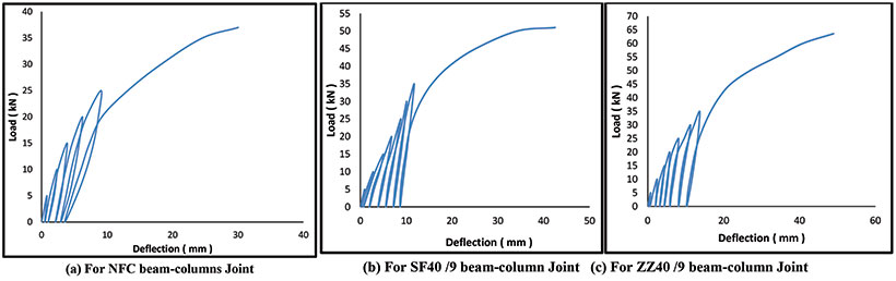
Figure 5: Load deflection curve for beam-column joints at LVDT-1
| Table 4: Parametric Study of HPC & HPFRC Beam-Column Joints | ||||
| Designation | First Crack Load, Pcr (kN) | Ultimate Load, Pu (kN) | First Crack Deflection (mm) | Ultimate Deflection (mm) |
| Δ cr | Δu | |||
| NFC | 13.8 | 37.0 | 7.356 | 30.050 |
| SF 40 / 6 | 14.2 | 40.5 | 6.026 | 40.020 |
| SF 40 / 8 | 15.0 | 43.2 | 6.705 | 41.920 |
| SF 40 / 9 | 18.6 | 51.0 | 7.366 | 42.500 |
| SF 40 / 10 | 15.8 | 48.5 | 6.225 | 39.660 |
| SF 50 / 6 | 14.5 | 46.5 | 5.788 | 39.315 |
| SF 50 / 8 | 16.7 | 48.2 | 6.738 | 40.915 |
| SF 50 / 9 | 19.6 | 55.0 | 7.241 | 41.920 |
| SF 50 /10 | 17.6 | 51.5 | 5.682 | 38.565 |
| ZZ 40 / 6 | 19.8 | 48.8 | 7.478 | 45.650 |
| ZZ 40 / 8 | 20.5 | 52.5 | 8.047 | 46.980 |
| ZZ 40 / 9 | 23.5 | 63.6 | 9.192 | 48.935 |
| ZZ 40 / 10 | 22.4 | 58.2 | 8.434 | 44.310 |
| ZZ 50 / 6 | 17.2 | 45.2 | 6.415 | 44.740 |
| ZZ 50 / 8 | 19.5 | 49.3 | 7.715 | 45.695 |
| ZZ 50 / 9 | 21.8 | 59.4 | 9.092 | 48.605 |
| ZZ 50 / 10 | 20.3 | 55.7 | 8.515 | 43.560 |
It has been observed that the first crack load (Pcr) and the ultimate load (Pu) of the HPFRC beam-column joint specimens have been significantly improved in comparison to NFC. It can therefore be inferred that the HPFRC utilizing the fiber content up to 9 percent increases load carrying capacity of the joint significantly. The enhancement, however, is not significant when fiber content is increased to 10%. The Vf = 9 is therefore considered as an optimum value.
The area under the curve upto the first crack load represents the resilience of the specimens. The result shows that the percentage increase in resilience was 488, 399, 361 and 357 for specimens ZZ 40/9, ZZ 50/9, SF 50/9 and ZZ 40/10 respectively. The area under the load deflection curve upto the failure of the specimens represents the energy absorption capacity, i.e. Toughness. The results illustrates that percentage increase in toughness was 302,262,226 and 211 for the specimens ZZ 40/9, ZZ 50/9, ZZ 40/10 and ZZ 40/8 respectively, as compared to NFC. The ductility is defined as the ability to sustain inelastic deformation by the structural member without significant loss in resistance and without substantial loss of strength. The percentage increase in ductility was 87, 82, 76, and 68 for specimens ZZ 50/6, SF 50/6, SF 40/6 and SF 40/10 respectively. The result values of resilience, toughness and ductility are shown in Table 5.
| Table 5: Ductility Associated Parameters for HPFRC Beam-Column Joint Specimens | |||||||||
| Specimen Designation | Resilience | Increase in Resilience (%) | Toughness(kN.mm) | Increase in Toughness(%) | Toughness Index | Ductility | Ductility Index | Increase in Ductility(%) | |
| I3 | I5 | ||||||||
| NFC | 22 | - | 516 | - | 9.27 | 14.98 | 3.20 | 4.20 | - |
| SF 40 / 6 | 52 | 139 | 1071 | 107 | 6.01 | 12.47 | 5.64 | 6.64 | 76 |
| SF 40 / 8 | 71 | 230 | 1247 | 141 | 5.79 | 12.61 | 5.25 | 6.25 | 64 |
| SF 40 / 9 | 91 | 322 | 1488 | 188 | 5.92 | 13,15 | 4.77 | 5.77 | 49 |
| SF 40 / 10 | 62 | 190 | 1284 | 149 | 6.72 | 13.23 | 5.37 | 6.37 | 68 |
| SF 50 / 6 | 57 | 164 | 1106 | 114 | 5.93 | 12.54 | 5.79 | 6.79 | 82 |
| SF 50 / 8 | 81 | 276 | 1290 | 150 | 5.53 | 12.66 | 5.07 | 6.07 | 59 |
| SF 50 / 9 | 99 | 361 | 1548 | 200 | 5.95 | 13.37 | 4.79 | 5.79 | 50 |
| SF 50 / 10 | 69 | 224 | 1349 | 161 | 6.24 | 13.48 | 5.78 | 6.79 | 81 |
| ZZ 40 / 6 | 75 | 249 | 1430 | 177 | 5.90 | 13.52 | 5.10 | 6.10 | 60 |
| ZZ 40 / 8 | 89 | 316 | 1608 | 211 | 6.04 | 14.15 | 4.84 | 5.83 | 51 |
| ZZ 40 / 9 | 126 | 488 | 2076 | 302 | 5.94 | 14.99 | 4.32 | 5.32 | 35 |
| ZZ 40 / 10 | 98 | 357 | 1685 | 226 | 6.88 | 15.22 | 4.25 | 5.25 | 33 |
| ZZ 50 / 6 | 62 | 190 | 1382 | 168 | 5.93 | 13.94 | 5.97 | 6.97 | 87 |
| ZZ 50 / 8 | 83 | 288 | 1564 | 203 | 6.91 | 14.68 | 4.92 | 5.92 | 54 |
| ZZ 50 / 9 | 107 | 399 | 1869 | 262 | 6.78 | 15.65 | 4.35 | 5.35 | 36 |
| ZZ 50 / 10 | 92 | 329 | 1502 | 191 | 5.88 | 13.12 | 4.12 | 5.12 | 29 |
The values of compressive strength, first crack load, ultimate load and deflection at peak load of present study are compared with those obtained by Ganeshan et al. (9) for SFRC based HPC beam column joint subjected to cyclic loading. It has been observed that the values corresponding to HPFRC based beam column joints are comparatively high in comparison to those corresponds to SFRC based beam column joints. This illustrates, HPFRC based beam column joint undergo very small deflection at ultimate load which is found to be 0.176 times the corresponding values in case of SFRC with Vf = 1%.
Ductility associated parameters like ductility index and toughness index increases significantly in HPFRC based beam column joints. HPFRC joints undergo small displacement without developing wider cracks when compared to NFC joint. The failure is characterized by multiple closely spaced finer cracks. This indicates that HPFRC based joints impart very high ductility which is one of the essential property for beam column joint. HPFRC based beam column joints would impart dimensional stability and integrity of the joints. The failure was found to be accompanied by dissipation of large amount of dissipation energy as the area under the curve corresponding to ZZ 40/9 percent fiber content was maximum illustrating high ductility. Ductility associated parameters were also studied but these form in the scope subsequent research papers.
Joint constructed with High Performance Light Weight Aggregate Fiber Reinforced Concrete (HPLWAFRC) would benefit greatly to provide safe and cost-effective alternatives due to reduced dead load which is a primary requirement of earthquake resistant structures (EARS). Structures of national importance and industrial structures of high strength demand can also be considered as potential applications. Further, if designed and constructed properly HPLWAFRC based beam column junction can be a very economical solution due to reduced weight of structures.
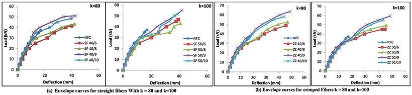
Figure 6: Comparison of the envelope curves
The envelope curves are also obtained by joining the peak points of each cycle. A comparison of envelope curves for different volume fraction of fibers is shown in Figure 6. It can be seen that HPFRC specimens show significant increase in load carrying capacity of the joint with increase in fiber contents. The increase in ultimate load with increase in fiber contents may be attributed to the facts that as and when micro cracks develop, fibers present in the matrix intercept the cracks and prevent them from propagating in the same direction [Ganesan and Indira, 2000] (9). Therefore, the cracks have to deviate and require more energy to propagate in this process, thereby resulting in higher load carrying capacity.
In cyclic loading, moreover, when unloading takes place, tip of the crack becomes blunt and during the subsequent cyclic loading, more energy is required to propagate the crack or to change the direction of crack propagation from the blunt crack tip. This in turn increases ultimate load capacity of the joint. It has been observed that toughness is maximum corresponding to specimen ZZ 40/9. It may therefore be inferred that energy absorption capacity of beam-column joint increases upto Vf = 9 percent, beyond which widening of multiple micro cracks started and additional load applied is dissipated in widening of these cracks.
Stiffness Degradation
During the testing of specimen under cyclic loading, the materials (i.e. concrete and steel) are subjected to loading, unloading and reloading operations, which starts the development of micro-cracks inside the joint, leading to failure of joint at ultimate load. Increase in the deformation due to development of cracks inside the beam-column joints subjected to cyclic loading, results in reduction in stiffness. To obtain the degradation of stiffness, the following method has been adopted.
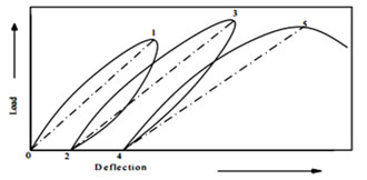
Figure 7: The method adopted for determination of secant stiffness
The above behaviour may be concluded to the fact that at the first cycle, micro-cracks would not have initiated and hence the fibers were not effective in the absence of crack formation. As the number of cycles increases, micro-cracks develop, and fibers which are distributed at random intercept these cracks and bridge across these cracks (9). During this process, stiffness of the HPFRC joints will not undergo much reduction when compared to NFC.
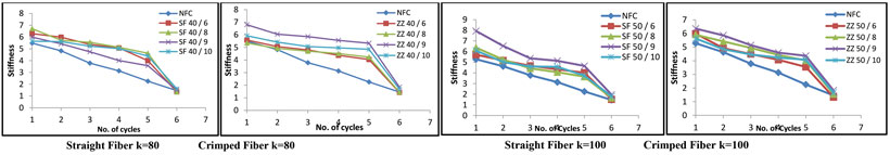
Figure 8: Relationship between stiffness and number of cycles
Failure Mechanism
The failure pattern of beam column junctions corresponding to various fiber contents is shown in Figure 9. It has been observed that multiple fine cracks were developed at the interface of HPFRC based beam-column joints specimens, and propagated away from the beam-column joints. As the load is increased further cracks propagates towards the beam fiber core rather than column fiber core region and the failure occurred in beam-column in beam core zone. It has further been observed that in case of straight fiber based specimens, failure occurred in fiber core portion of the beam, as illustrated in Figure 9 (b). However, in crimped fiber based specimens, multiple hair line cracks were developed in beam portion first which propagated towards the column core on further increasing the load, as illustrated in Figure 9(c). Multiple fine cracks were found to develop in almost all specimens indicating that inclusion of fibers impart significant ductility in beam-column joint region which is considered as one of the essential property for structures constructed in earthquake prone regions. The dimensional stability and integrity of the joint was also found to be improved. It may therefore be inferred that the spacing of lateral ties in columns and stirrups in beams, in the beam-column joints region may be increased due to inclusion of fibers to avoid congestion of conventional reinforcement.
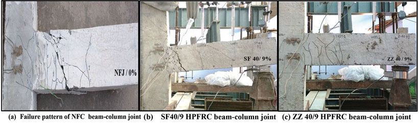
Figure 9: Failure pattern in beam-column joints
Ductility associated parameters, likewise, indicative of energy absorption capacity, ductility and ductility index were also calculated, Table 5. HPFRC based beam-column joints were found to exhibit increase in ductility by about 87 and 82 percent in HPFRC beam-column joint corresponding to ZZ 50/6 and SF 50/6 respectively when compared with their companion specimen NFC. Likewise, toughness (or energy absorption capacity) has been found to increase by 302 and 262 percent corresponding to ZZ 40/9 and ZZ 50/9 designated specimens whereas resilience has been found to increase by 488 and 399 percent in specimen designated as ZZ 40/9 and ZZ 50/9 respectively, when compared with their companion control specimen NFC.
In summary, it may therefore be inferred that crimped fibers provided in optimum amount of 9 percent by volume with aspect ratio 80 can substitute for conventional transverse reinforcement thereby allowing for relaxation in stirrups congestion which is many times experienced in seismic detailing of beam-column joints. A simplified design equation to determine fiber contents needed to replace stirrups whilst retaining same level of strength and ductility may be developed.
Conclusions
- The compressive, split tensile and flexural strength values have been increased by 36, 230 and 188 percent respectively in HPFRC based controlled specimens corresponding to ZZ 40/9 when compared with their companion specimen of NFC.
- The first crack load and the ultimate load have been found to increase by 70 and 72 percent respectively in HPFRC based beam-column joints corresponding to ZZ 40/9 when compared with their companion specimen NFC.
- The ductility associated parameters like toughness and resilience have been found to increase tremendously by 302 and 488 percent in HPFRC based beam column junctions corresponding to ZZ 40/9.
- An optimum fiber content has been found to be 9 percent with aspect ratio 80 incase of crimped fibers.
- Addition of steel fibers significantly improves dimensional stability, strength consistency and integrity of the beam-column joints.
- The addition of fibers in optimum amount led to significant enhancement in ductility which is particularly significant in earthquake resistant structures.
- Steel fibers in optimum amount can substitute for conventional transverse reinforcement and thus allow relaxation in stirrups congestion experienced in seismic detailing.
- The addition of steel fibers to beam-column joint decreases rate of degradation of stiffness as compared to NFC based specimens. Hence, addition of steel fibers in beam-column joints can be considered as an useful solution in case of joints subjected to cyclic loading.
- ACI (2002), “Recommendations for Design of Beam-Column Connections in Monolithic Reinforced Concrete Structures”, Report 352R-02, American Concrete Institute, Farmington Hills, U.S.A.
- V. Kumar, B.D. Nautiyal and S. Kumar, “A study of exterior beam-column joints”, The Concrete Journal, vol.65, pp. 2821-2836, 1991.
- Naaman, A.E., and Shah, S.P., (1979). “Fracture and Multiple Cracking of Cementitious Composites”. Fracture Mechanics Applied to Brittle Material Proceeding, 183-201.
- T.Jiuru, H. Chaobin,Y. Kaijian, and Y Cheng, “Seismic behavior and shear strength of framed joints using steel.
- B.Singh, S. K. Kaushik, “Fiber reinforced concrete corners under opening bending moments” Journal of Structural Engineering, vol.28, (2), pp. 89-97, July-Sept., 2001.
- G.S Thirugnanam, P. Govindan and A.Sethurathnam, “Ductile behavior of sifcon structural members”, Journal of Structural Engineering, vol.28 No.1 pp. 27-32, April-June, 2001
- Z. Bayasi and M.Gebman, “Reduction of lateral reinforcement in seismic beam-column connection via application of steel fibers”, ACI Structural Journal, 99(6), pp.-772-780, 2002.
- P.G Bakir, “Seismic resistance and mechanical behavior of exterior beam-column joints with crossed inclined bars”, Structural Engineering & Mechanics, 6(4), pp.-493-517, 2003.
- N. Ganeshan, P.V Indira and Abraham, “Steel fiber reinforced high performance concrete beam-column joints subjected to cyclic loading” ISET Journal of Earthquake Technology, Technical Note, vol.44, pp. 445-456 Sept.-Dec., , 2007.
- M. Elnono, M. Hamed, M. Salem. Ahmed Farahat and H. AsrafElzanaty, “Use of slurry infiltrated fiber concrete in reinforced concrete connections subjected to opening moments”, Journal of Advanced Concrete Technology, vol. 7 (1), 2009.
- Ganesan, N. and Indira, P.V. Latex “Modified SFRC Beam-Column Joints Subjected to Cyclic Loading”, The Indian Concrete Journal, vol.74, No.7 (2000), pp. 416-420.
- H.K Kim, and H. K. Lee, “workability and mechanical, acoustic, and thermal properties of lightweight aggregate concrete with a high volume of entrained air”, Construction and Building Materials, 29, pp.193-200, 2012.
- H K Sharma, R K Sharma and Shashi Kant, “Behaviour of High Performance Reinforced Concrete Beam Column Joints”, Proceedings of International Conference on Transportation and Civil Engineering (ICTCE’15), London, March 21-22, 2015, pp. 108-115.
- ACI(1998).” Standard Practice for Selecting Proportions for Structural Lightweight Concrete”,ACI 211.2-98, American Concrete Institute, Farmington Hills, U.S.A
- Shannag,M.J., Abu-Dyya, N. and Abu-Farsakh.G. “Lateral LoadResponse of High Performance Fiber Reinforced Concrete Beam-Column Joints”, Construction and Building Materials, Vol.19, No.7, pp.500-508.
Published on:
08 May 2017
Published in: NBM&CW May 2017
Share:
We Value Your Comment