Seismic Retrofitting of RC Beam-Column Connections
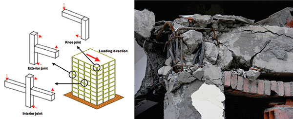
Designing beam–column joints is considered to be a complex and challenging task for structural engineers, and careful design of joints in RC frame structures is crucial to the safety of the structure. Although the size of the joint is controlled by the size of the frame members, joints are subjected to a different set of loads from those used in designing beams and columns. As a result, it is necessary to pay special attention to the detailing of reinforcement within a joint region. [36] It has been identified that the deficiencies of joints are mainly caused due to inadequate design to resist shear forces (horizontal and vertical) and consequently by inadequate transverse and vertical shear reinforcement and of course due to insufficient anchorage capacity in the joint. Therefore, inadequate transverse reinforcement and insufficient anchorage in the joint are two major problems of joints designed as per non-seismic guidelines [2]. These problems have been highlighted, in recent past, by the damages observed in devastating earthquakes in different countries. The two major failure modes for the failure at joints are (a) joint shear failure (Fig. 2) and (b) end anchorage failure
|
|
| Figure 1: Terminology of RC beam-column connections Source: Jaehong Kim et. al. 2009 [11] |
Figure 2: Joint Shear Failure Source: A. Sharma et al. (2011) [1] |
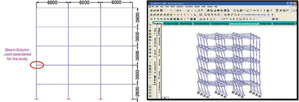
In this study, a conventional four-storey RC school building (Fig. 3) is considered for analysis, design and detailing of exterior joint. Different failure modes are expected in beam-column joints depending on the type of joint (exterior or interior) and the adopted structural details. Due to sudden discontinuity of the geometry, exterior joints are found to be more vulnerable to seismic loading than the interior one because it demands to explore additional parameters such as bond-slip of reinforcement [Pampanin et al. (2003)]. Hence, in the present study, exterior beam-column joint has been chosen for investigating the performance under seismic type loading.
|
|
| Figure 3: General Arrangement of the Building Frame Considered for the Study | Figure 4: Graphical User Interface of STAAD.Pro |
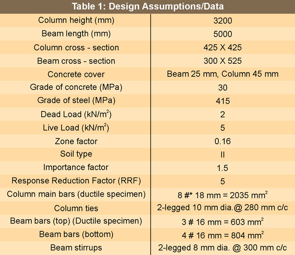
Characteristic compressive strength of concrete and tensile strength of steel used in the specimen have been taken as 30 MPa and 415 MPa, respectively. The specimen has the following general and cross-sectional dimensions: height of column is 3200 mm having cross-sections of (425 x 425) mm and length of beam is 2500 mm with beam size (300 x 525) mm. For casting the specimen, weight ratio of cement: sand: coarse aggregate was adopted as 1 (cement): 2.25 (fine aggregate): 2.35 (coarse aggregate-60% 10 mm size, 40% 20 mm size): 0.5 (w/c). Ordinary Portland Cement (OPC) with 28 days minimum compressive strength of 53 MPa is to be used.
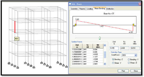
Figure 5: Design of specimen using STAAD.Pro
The geometry of the components (top and bottom portion of column and beam length from joint face) is chosen to match the bending moment distribution at the joint for which it is designed. Seismic analysis (Response Spectrum Analysis) of the framed structure (Fig. 3) has been performed using STAAD.Pro to obtain the design forces. Design assumptions are mentioned in Table 1. The following provides a broad overview of the basic modelling, analysis, and design processes using STAAD.Pro.
The results obtained from the analysis of a 3 - bay four-storey RC building under the load combinations are used to design the specimen (Fig. 4). Finally, as shown in Fig. 5, the geometry of the components (top and bottom portion of column and beam length from joint face) is chosen to match the bending moment distribution at the joint for which it was designed.
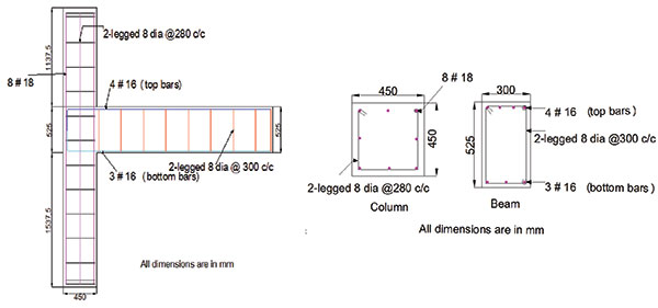
Figure 6: Reinforcement Details of Specimen
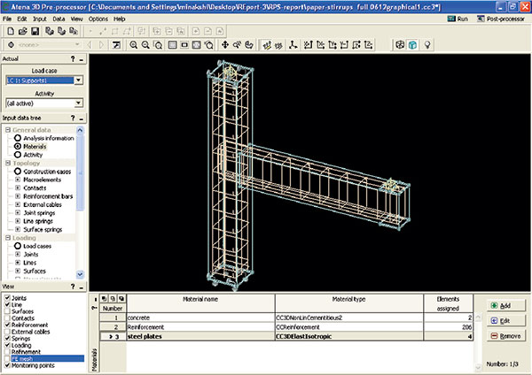
Figure 7: Graphical User Interface of ATENA 3D Pre-Processor
In a numerical investigation, it is utmost important to provide the material properties as realistic as possible. There are many nonlinear finite element analysis programs of RC structures available. e.g. ATENA, ANSYS, Drain-2DX, MSC.MARC etc. Considering its application, effectiveness, user friendliness, availability, ATENA [1] has been selected for carrying out numerical analysis of the specimen designed for the study.
Published on:
18 February 2015
Published in: NBM&CW February 2015
Share:
We Value Your Comment