Popular Non Destructive Testing of Concrete Structure-review of Std. Methods
R. B. Singh, Chief Coordinator, ANULAB, Agra
Introduction
In a short span of ten years after Bhuj earthquake, nondestructive testing has achieved an important place in the Quality Assurance of hardened concrete and the evaluation of existing concrete structure with regard to their strength & durability.This paper deals with the popular, economical and widely used NDT tests in the field in general & national highways in particular. The paper also has discussion on combined methods, when more than one nondestructive test method is used and condition assessment is based on the data obtained from Rebound Hammer, UPV & Core tests.
The aim of the paper is to address the field engineers engaged in evaluation of quality of hardened concrete. An attempt has been made to keep the theoretical part of the subject to an absolute minimum, where necessary tables of std. values, photographs & comparisons have been included. Research oriented engineers who would want through treatment of the material and a more basic approach are referred to the original std. specification, NDT handbooks & original papers and literature on the subject given as reference. Although nondestructive tests are relatively simple to perform & instrument based, the analysis and interpretation of the test data are not easy, because concrete is a complex material, hence the engineers are cautioned that interpretation of the test data must always be carried out by trained specialists in NDT rather than by technicians performing the tests.
If used properly, nondestructive tests can form a vital link in the chain of testing and evaluation of concrete and concrete structures, which starts with crushing of 150 mm cubes and may end with load testing of finished structure.
At present, standard method of determination strength of hardened concrete consist of testing of concrete cubes (03 Nos. of 150X150X150 mm) in compression testing machine following the std. test method IS: 516. In case of PQC for rigid pavement, beam specimens are broken for flexural strength. The strength tests, regardless of the type, are excellent for determining the criteria of quality & quality control during construction, but they leave a lot to be desired. The main disadvantage of such tests are delay in obtaining test results, the fact that the test specimen may not be truly representative of the concrete in a structure, the necessity of stressing the test specimen to failure, the lack of reproducibility in the test results and the relativity high cost of testing & wastage of concrete in form of cubes.
For the NDT tests to monitor the service behavior of concrete structures over a long period, it was imperative that these tests be nondestructive. This approach, though new for the testing of concrete, had long been used in the testing of metals in petroleum exploration & refining projects. The direct determination of strength implies that concrete specimen must be loaded to failure; it becomes clear that nondestructive methods of testing cannot be expected to yield absolute value of strength.
These methods, therefore, attempt to measure some other property of concrete from which an estimate on its strength, its durability and its elastic parameters is obtained. Such properties of concrete are its hardness, rebound number and its ability to allow ultrasonic pulse velocity to propagate through it. The electrical properties of the concrete, allow us to estimate its moisture content, density, thickness and its cement content. Based on above, various nondestructive methods of testing concrete have been developed.
Popular NDT Tests for Concrete Used in field are:
- Rebound Hammer Test- RH Test
- Ultrasonic Pulse Velocity- UPV Test
- Combined Method UPV & RH Test
- Core Extraction for Compressive Strength Test
- Ingredient Analysis of Concrete Core
- Concrete Cover Measurement by Laser Based Instt.
1. Rebound Hammer–RH (Schmidt) Test
In 1948, a Swiss Engineer, Ernst Schmidt from Zurich developed a test hammer for measuring the hardness of concrete by the rebound principle. Since then the Rebound Hammer (RH) test has gained recognition at construction site & precast Industry.Principle
The Schmidt Rebound Hammer is principally a surface hardness tester with little apparent theoretical relationship between the strength of concrete and the Rebound number of the hammer. However, within limits, empirical correlations have been established between strength properties & rebound number. This correlation between the concrete strength and rebound number is required to be established at site/field laboratories before it is used for strength estimation of concrete. Sometimes it is referred as fieldcalibration of rebound hammer. Lab calibration are based on Brinell Hardness & Rebound Nos. are checked on std. calibrated Anvil for the purpose. Proper site calibrations eliminate the lab calibration, which is for the checking of hammer performance.Rebound Number and Compressive Strength
There is a general correlation between compressive strength of concrete and the hammer rebound number. Coefficients of variation for compressive strength for a wide variety of specimens averaged 25%. The large deviations in strength can be narrowed down considerably by proper calibration of the hammer, which allows for various variables discussed earlier. By consensus, the accuracy of estimation of compressive strength of test specimens cast, cured, and tested under laboratory conditions by a properly calibrated hammer lies between ±15 and ±20%. However, the probable accuracy of prediction of concrete strength in a structure is ±25%.Limitations and Usefulness
The limitations of the Schmidt hammer are many; these should be recognized and allowances be made when using the hammer. It cannot be overstressed that this instrument must not be regarded as a substitute for standard compression tests but as a method for determining the uniformity of concrete in the structures and comparing one concrete by the Schmidt hammer within an accuracy of ±15 to ±20% may be possible only for specimens cast, cured, and tested under identical conditions as those from which the calibration curves are established. The prediction of strength of structural concrete by using calibration charts based on the laboratory test is not recommended.2. Ultrasonic Pulse Velocity-UPV Test
The test instrument consists of a means of producing and introducing a wave pulse into the concrete and a means of sensing the arrival of the pulse and accurately measuring the time taken by the pulse to travel through the concrete.Portable ultrasonic testing equipment are available. The equipment is portable, simple to operate, and includes rechargeable battery and charging unit. Typically, pulse times of up to 6500 os can be measured with 0.1-os resolution. The measured travel time is prominently displayed. The instrument comes with a set of two transducers, one each for transmitting and receiving the ultrasonic pulse. Transducers with frequencies of 25 to 100 KHz are usually used for testing concrete. These transducers primarily generate compressional waves at predominantly one frequency, with most of the wave energy directed along the axis normal to the transducer face.
Factors Affecting UPV Test
Although it is relatively easy to conduct a pulse velocity test, it is important that the test be conducted such that the pulse velocity readings are reproducible and that they are affected only by the properties of the concrete under test rather than by other factors. The factors affecting the pulse velocity can be divided into two categories: (1) factors resulting directly from concrete properties; and (2) other factors. These influencing factors are discussed below:Effects of Concrete Properties
- Aggregate Size, Grading, Type, and Content
- Cement Type
- Water-Cement Ratio
- Admixtures
- Age of Concrete
Other Effects
- Transducer Contact
- Temperature of Concrete
- Moisture and Curing Condition of Concrete
- Path Length
- Size and Shape of a Specimen
- Level of Stress
- Presence of Reinforcing Steel
Applications of UPV Tests
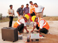 |
| UPV Test being perform on Deck Slab of Flyover on NH-2 at Firozabad (U.P.), India |
- Estimation of Strength of Concrete
- Establishing Homogeneity of Concrete
- Studies on the Hydration of Cement
- Studies on Durability of Concrete
- Measurement of Surface Crack Depth
- Determination of Dynamic Modulus of Elasticity
Combined Method–UPV & RH Test
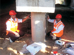 |
| UPV Test being perform on Minor Bridge Pier on NH-11 at Dausa (Raj.), India |
The interpretation of the pulse velocity measurements in concrete is complicated by the heterogeneous nature of this material. The wave velocity is not determined directly, but is calculated from the time taken by a pulse to travel a measured distance. A piezoelectric transducer emitting vibration at its fundamental frequency is placed in contact with the concrete surface so that the vibrations travel through the concrete and are received by another transducer, which is in contact with the opposite face of the test object.
Conclusion
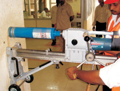 |
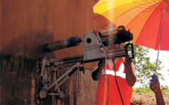
| Portable Concrete Coring Machine (BOSCH) in Horizontal Operation on RCC Column |
The validity of a combined technique can be evaluated from the degree of improvement this additional test provides to the accuracy and reproducibility of predictions, vs. the additional cost and complexity of the combined method and the extent to which it is practicable to perform the additional test in site.
Of the various combinations proposed by different researchers and from the reported data it seems that only the combined techniques based on the Ultrasonic Pulse Velocity and surface hardness measurement have been adopted for practical evaluation of the in site compressive strength of concrete.
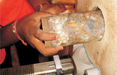 |
| Concrete Core from RCC Column being Extracted after Diamond Bit Core Drilling |
When testing suspect quality concrete of unknown composition, it is highly desirable to develop a prior correlation relationship in which factor such as aggregate type and approximate age of concrete are introduced as constants. For most in site concrete an approximate age and petrological type of aggregate can be determined, thus reducing the number of uncontrollable variables.
 |
| Core Drilling in Progress on the Inside Wall (After Epoxy Grouting) of Box Culvert on NH-26 at Sagar, (M.P.) |
When a reliable prior correlation relationship exists for a particular concrete type, the use of combined nondestructive techniques provides a realistic alternative to destructive testing. It often possible to perform a large and thus a representative number of tests at a reduced cost compared with coring, and without an adverse effects on the integrity of structural element.
Core Extraction for Compressive Strength Test
Test Specimens
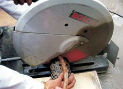 |
| Core Dressing-Cutting in Lab using Diamond Wheel Cutter in the Lab before Capping and Curing for Compressive Strength Test on CTM |
Procedure
Core Drilling- A core specimen taken perpendicular to a horizontal surface shall be located, when possible, with its axis perpendicular to the bed of the concrete as originally placed.Measurement of Drilled Core Specimens
Mean Diameter- The mean diameter shall be determined to the nearest millimeter from three pairs of measurements. The two measurements in each pair shall be taken at right angles to each other, one pair being taken at the middle of the core and the other pairs at the quarter points of the depth. The mean of the six readings shall be taken as the diameter.Position of Reinforcement- The positions of any reinforcement shall be determined by measuring to the nearest millimetre from the centre of the exposed bars to the top of the core. The diameter and, if possible, the spacing of the bars shall be recorded, and also the minimum top and bottom cover.
 |
| Extracted Three Numbers of Cores (Making One Sample) from RCC Structure-Box Culvert on NH-26 at Sagar (M.P.) |
Apparatus
Number of Specimens- At least three specimens, preferably from different batches, shall be made for testing at each selected age.Procedure- Specimens stored in water shall be tested immediately on removal from the water and while they are still in the wet condition. Surface water and grit shall be wiped off the specimens and any projecting fins removed. Specimens when received dry shall be kept in water for 24 hours before they are taken for testing. The dimensions of the specimens to the nearest 0.2 mm and their weight shall be noted before testing.
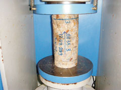 |
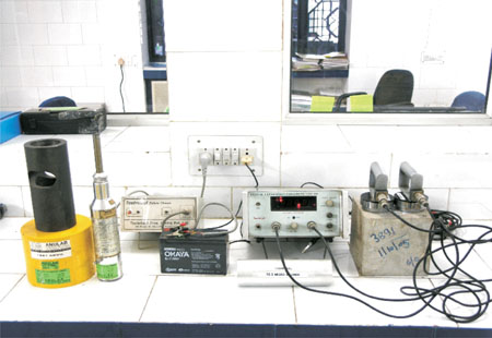
| Capped and Cured Concrete Core Specimen under Compressive Strength Test in CTM |
A correction factor according to the height/diameter ration of specimen after capping shall be obtained from the hardened curve. The product of this correction factor and the measured compressive strength shall be known as the corrected compressive strength, this being the equivalent strength of a cylinder having a height/diameter ratio of two. The equivalent cube strength of the concrete shall be determined by multiplying the corrected cylinder strength by 5/4.
Report- The following information shall be included in the report on each test specimen/core:
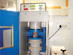 |
| Capped and Cured Concrete Core Specimen under Compressive Strength Test in CTM |
- Identification Mark,
- Date of test,
- Age of Specimen,
- Curing Conditions, Including date of Manufacture of Specimen in the Field,
- Weight of Specimen
- Dimensions of Specimen,
- Cross-Sectional Area,
- Maximum Load,
- Compressive Strength, and
- Appearance of Fractured Faces of Concrete and Type of Fracture, if these are Unusual.
Reference
- IS: 13311 (Part 1): 1992 Non-Destructive Testing of Concrete-Method of Test; Part 1-Ultrasonic Pulse Velocity.
- IS: 13311 (Part 2): 1992 Non-Destructive Testing of Concrete-Method of Test; Part 2-Rebound Hammer.
- BS: 1881: Part 203: 1986 British Standard-Testing Concrete Part 203. Recommendations for Measurement of Velocity of Ultrasonic Pulses in Concrete.
- ASTM C 597-02 Standard Test Method for Pulse Velocity through Concrete.
- Handbook on Nondestructive Testing of Concrete, Second Edition, Edited by V.M. Malhotra and N.J. Carino, ASTM & CRC Press, 2006.
- Testing Hardened Concrete: Nondestructive Methods by V.M. Malhotra, Published Jointly by the IOWA State University Press & American Concrete Institute (ACI) 1976.
- Near-Surface Testing for Strength and Durability of Concrete, Editor P.A.M. Basheer, Fifth CANMET/ACI International Conference on Durability of Concrete.
- Advanced Testing Methods and Damage Assessment of Distressed Concrete Structures by H.G. Sreenath Proceedings of the Advanced Course on Structural Health Monitoring, Repair and Rehabilatation of Concrete Structures Feb. 4-6, 2006, SERC, CSIR, Chennai.
- Advanced Course on Non-Destructive Testing and Evaluation of Concrete Sructures, Organised by SERC, CSIR.Chennai, 2006.
- Properties of Concrete, Fourth Edition 1996, by A.M. Neville, Published by ELBS-Longman.
Acknowledgement
The article has been reproduced from the proceeding of "National Seminar on Green Structures for Sustainability" with the kind permission from the event organisers.
Published on:
09 October 2010
Published in: NBM&CW October 2010
Share:
We Value Your Comment