Methods & Factors for Design of Slabs-on-Grade
Classification of slabs-on-grade based on design strategy
There exist many terminologies and typologies for floors and slabs-on-grade based on different factors. Given below is a list of floor slabs grouped according to the material used which can be easily extended to the design strategy to be adopted for each of them.
- Type A
- Type B – Slab with shrinkage control reinforcement
- Type C – Post-tensioned slab for crack control
- Type D – Structurally reinforced slab
- Type E – Fibre reinforced concrete (FRC) slab
- PCA method
- Wire Reinforcement Institute (WRI) charts
- US Army Corps of Engineers (COE) method
- ACI 360 R- method
- TR34 method
Design strategies for slabs-on-grade
Design strategies for slabs-on-grade depend upon the expected response of the slab system to the most critical loading configuration. The response in turn is dependent upon the boundary conditions, subgrade characteristics, and the mechanical property of the material to be used in the slab. The two mechanistic philosophies adopted for design are:
- Elastic design: In this strategy, the stresses and slab responses are considered to be elastic and no cracking is allowed. This approach would be suitable for cases where the slab is unreinforced or with minimum steel rebar/mesh/fibre reinforcement for shrinkage and other secondary effects. (ICI TC/09).
- Inelastic design: In the design methods based on this strategy, the stresses in the slab are considered beyond elastic regime with some level of cracking allowed. These methods of design may be employed for slabs which are sufficiently ductile, possessing necessary reinforcements in terms of fibres or mesh reinforcement to allow for redistribution of stresses even after cracking.
Though the different design methods (discussed in the first section of the article) are more beneficial for certain material and slab configurations, there are certain commonalities in the methods as listed below.
- Thickness design is predominantly related to flexural strength of concrete except in type C and type D slabs.
- Required flexural strength is one of the material parameters used in the design which is the function of the applied load, radius of relative stiffness, thickness of slab and contact radius of the load (each of these parameters will be discussed in detail in the following section).
- Reinforcement for crack control due to shrinkage and thermal stresses should be provided and is often expressed as % of slab cross-sectional area.
- Load details
- Soil details
- Material details

Applied load
The details needed about load include:
- Type of load
- Configuration of load
- Magnitude of load
- Critical locations of load
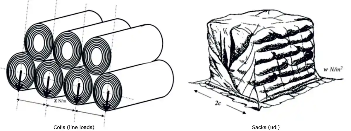 Figure 1: Type of loads on slabs-on-grade (reproduced from ICI TC /09)
Some of the commonly applied loadings on a floor slab is given in Figure 1. One major concern is the typical way of specifying the applied load on flooring slabs as a UDL of P ton/m. In actual practice, there exists slight chance of having a true udl since the loads are mostly placed on frames or racks which translates to a point load or line load. Thus, specifying a udl for design should be avoided as it does not represent the actual loading condition.
 Figure 2: Critical locations of load (reproduced from Critical Stress Combination for Rigid Pavements - Civil Engineering Soft Studies (civilengineering-softstudies.com))
With respect to the magnitude of load, the actual load should be factored appropriately to take care of the static and dynamic effects and covert it to the design load. The critical locations of load considered for design is shown in Figure 2.
Soil and subgrade details
A detailed discussion about the soil and subgrade characteristics are given in the chapter 3 of the technical guideline document on Ground Supported Slabs, by Indian Concrete Institute, ICI TC 09. With respect to design, a commonly adopted approximation for the subgrade behaviour is that the subgrade is simulated by a dense liquid (Winkler Foundation), which assumes that the stresses at any point are independent of stresses at other points and are proportional to the degree of depression (Westergaard 1945, Losberg 1961, Meyerhof 1962, Cachim 1999, Elsaigh et al. 2005). The soil is characterized by the resilient constant k = ps/w, where k is the modulus of soil reaction, representing the stiffness of the subgrade, ps is the soil reaction pressure and w is the deformation of the soil at a point. Modulus of subgrade reaction, k could be obtained from CBR value using the Table 2 of IRC 58.
Materials parameters
In addition to soil parameters, other material parameters needed for design include:
- Grade of concrete
- Type of steel used
- Material safety factors
- Contact radius of load, a – determined from the tyre dimensions and pressure in case of wheel loads and from the base plate dimensions in case of rack loading.
- Elastic modulus of concrete
- Flexural strength of concrete
- Poisson’s ratio of concrete
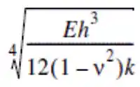
- Relative stiffness of slab in relation to the soil
Radius of relative stiffness, l =
The choice of slab dimensions and joint spacing may at times be governed by temperature variation and shrinkage stresses, in order to restrict curling and transverse cracking. Contraction joints are then needed at appropriate spacing to limit the restraint on the slab, for which the following recommendations compiled from existing standards maybe considered:
- Thickness, h - These values may be assumed based on previous experience or based on existing solutions in similar cases.
- Length/width ratio of the slab = 1 - 1.5 (TR34:2003, TR34 2013)
- Largest dimension between joints to be restricted to 4.5-6 m depending upon the thickness h, with the smaller value for higher thickness (TR34:2003, TR34:2013, IRC 15, Delatte, 2014). A maximum joint spacing of L = 24 h has been suggested by Delatte (2014).
- Joints should normally be located along the column lines with intermediate joints located at equal spacing between them (ACI 360R).
- Typically, sawn joints are recommended with groove widths not less than 3 mm and depths of about 1/3rd to 1/4th of the thickness of the slab (IRC 15:2002).
Design Methodologies
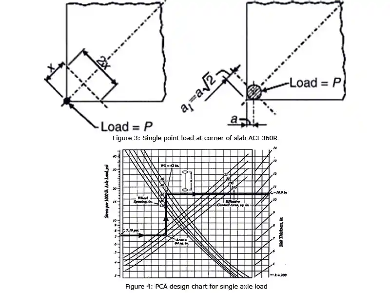
In this method, the design thickness is calculated based on the allowable moment for the combination of thickness, grade of concrete and subgrade modulus for each critical load position. An example of this approach is the design equations as per ACI 360 R for single point load at the corner of slab illustrated in figure 3.
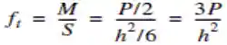
Another commonly used design document which adopts elastic design is using the PCA charts as shown in figure 4.
Inelastic design methodology: In this method, the slab-on-grade is assumed to be sufficiently ductile to allow for stress redistribution and thereby go beyond the first crack in the concrete and fully mobilize the plastic moment capacity of the slab. This is typically achieved by providing enough reinforcement in the form of fibres, or reinforcement bars or mesh (at the top and bottom) to allow for yielding of the sections. In the case of FRC, the requirement of sufficient plastic rotation is ensured by a characteristic equivalent flexural strength value fe3,k>0.3fct,k, where fct,k is the flexural tensile strength of FRC and fe3.k is the equivalent flexural strength of FRC both obtained from the flexural toughness test specified in IS 17161 or ICI TC/ 01.1. For all cases with fe3,k-values less than this specified minimum, the design should be done as per elastic design procedures discussed earlier.
The maximum allowable load is estimated by considering rigid-plastic behaviour, using yield line analysis. Failure is assumed to occur when the yield lines along the slab section form a mechanism (TR 34:2003, 2013, Meyerhof 1962). The yield line patterns would depend on the type of loading, slab dimensions and end conditions, as well as the soil pressure distribution (Losberg 1961, Meyerhof 1962, Baumann and Weisberg 1983, Meda 2003). Consequently, various possible load cases have to be considered, an example of which is shown below.
Example- Inelastic design for single point load located at the interior of the slab.
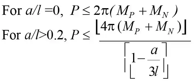
For interior loading, the failure may be characterized by a fan pattern as shown in Figures 5(a) and 5(b). Here, radial cracks initially appear at the bottom of the slab and widen, followed by circumferential cracking. The moments along the radial yield lines equal the plastic moment capacity (MP) of the concrete and the negative moment (MN) at the top of the slab reaches the flexural capacity of the concrete. The appearance of crack at the top is considered as the failure state (Figure 5(b)).
(2)
For values between a/l> 0 and a/l = 0.2, linear interpolation of values may be carried out.
Moment capacity estimates for inelastic design
Fibre Reinforced Concrete (FRC) Slab
The plastic moment capacity in the FRC slab is taken as a function of post-cracking flexural strength, represented by the equivalent flexural strength specified in ICI/TC 01.1. Consequently, the plastic moment capacity per unit length of the slab is estimated as:
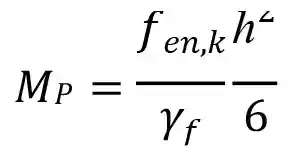
where fe3,k is the characteristic equivalent flexural strength of concrete (obtained from the flexural test of an unnotched prism as per ICI TC/01.1), and h is the thickness of the slab and gf is the material safety factor for FRC.
The negative moment capacity will be a function of the flexural strength (or modulus of rupture) of the concrete (obtained from the same flexural test) as:
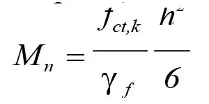
where fct,k is the characteristic value of the flexural strength of the concrete.
The corresponding moment estimates are used in the design equations corresponding to each yield pattern.
Rebar/ Mesh Reinforced Concrete (RRC) Slab
The inelastic moment capacity in the RRC will be the sectional bending capacity of the reinforcement at a particular level below the neutral axis. Consequently, the inelastic positive sagging moment capacity per unit length of the slab is:
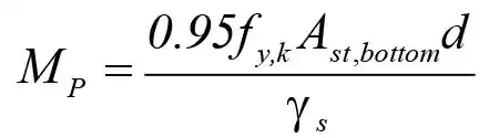
where fy,k is the characteristic yield strength of rebar steel, Ast,bottom is the area of steel at the bottom, d is the effective depth of the slab and γs is the material safety factor of steel.
The negative moment capacity will be the cracking moment of concrete on top. However, the RRC slab should have enough residual moment capacity at the top to prevent a brittle failure by the provision of adequate top reinforcement. The negative capacity for RRC is given as:
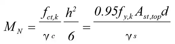
where fct,k is the characteristic value of the flexural strength of the concrete, h is the total depth of the slab, γc is the material safety factor of concrete, fy,k is the characteristic yield strength of rebar steel, Ast,top is the area of steel at the top, d is the effective depth of the slab and γs is the material safety factor of steel.
Plugging in the capacity values of MP and MN in the inelastic analysis equations discussed earlier completes the design process for the load stresses.
Design for thermal and shrinkage stresses
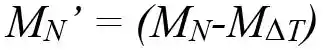
Where the temperature variations are significant, the design has to account for thermal stresses. These additional flexural stresses, fDT reduce the negative moment capacity to resist applied loads, affecting the failure occurring and thereby the negative moment capacity has to be modified as:
For the hardened concrete, the shrinkage stresses can be considerably reduced by providing friction relief layer such as a polythene sheet so as to reduce the restraints on the slab and by providing joints at adequate intervals. If the stress levels in concrete due to shrinkage is considerable, an approach similar to that used for temperature curling stresses is recommended. Thereby, the shrinkage stresses, Msh estimated from the ultimate (free) shrinkage strain values (esh) may be reduced from the total negative moment capacity, as

where Msh is estimated as

In the above expression fsh is the flexural stress due to shrinkage strain which is calculated as:
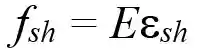
where, E is the modulus of elasticity of concrete and esh is the ultimate shrinkage strain.
| Comparison of elastic design method and in-elastic design method for slabs-on-grade A summary of the comparison of the two methods: | |
| Elastic design method | Inelastic design method |
|
|
- The design of slabs-on-grade should be done scientifically.
- Choice of the design strategy is related to the type of slab.
- Use of inelastic design methods could prove more economical both with respect to thickness as well as service life.
- ICI TC 09, Guidelines on Ground Supported Concrete Slabs for Industrial Flooring Applications, Indian Concrete Institute.
- Westergaard, H. M. (1945) Technical Memorandum on- New Formulas for Stresses and Deflections in Concrete Airfields, Navy department bureau of standards, University of California, September.
- Losberg, A. (1961) Design Methods for Structurally Reinforced Concrete Pavements, Transactions of Chalmers University of Technology, Sweden.
- Meyerhof, G. G. (1962) Load Carrying Capacity of Concrete Pavements, Journal of the Soil Mechanics and Foundations Division, Vol. 88, No. SM3, pp 89-116.
- Cachim, P. B. (1999) Experimental and Numerical Analysis of the Behaviour of Structural Concrete Under Fatigue Loading With Applications to Concrete Pavements, Doctoral thesis, Faculty of Engineering, University of Porto, Portugal.
- Elsaigh, W. A., Kearsley, E. P. & Robberts, J. M. (2005) Steel Fibre Reinforced Concrete for Road Pavement Applications, Proc. of 24th Southern African Transport Conference (Pretoria), South Africa, pp 191-200.
- Elsaigh, W. A. (2007) Modelling the Behavior of Steel Fibre Reinforced Concrete Pavements, Doctoral Thesis, Faculty of Engineering, University of Pretoria.
- IRC: 58 (1988) Code for Design of Plain Jointed Rigid Pavements, Indian Road Congress, New Delhi.
- IRC 58 (2010) Guidelines for Design of Plain Jointed Rigid Pavements for Highways, Indian Road Congress, New Delhi.
- TR 34 (2003) Concrete Industrial Ground floors: A Guide to Design and Construction, The Concrete Society, England.
- TR34 (2013) Concrete Industrial Ground floors: A Guide to Design and Construction, The Concrete Society, England.
- Delatte, N. J. (2014) Concrete Pavement Design, Construction and Performance, Second edition, CRC Press Publications, Taylor & Francis Group.
- ACI 360R (2010) Guide to Design of Slab-on-Ground, American Concrete Institute, Detroit, USA.
- Nayar, S. K., and Gettu, R., (2017) Design Methodology for Fibre Reinforced Concrete Slabs-on-grade Based on Inelastic Analysis, Indian Concrete Journal, Vol. 91, No. 3, pp 26-36.
- Nayar, S. K., Gettu, R., and Krishnan, S., (2014) Characterisation of the Toughness of Fibre Reinforced Concrete - Revisited in the Indian Context, Indian Concrete Journal, Vol. 88, No. 2, pp 8–23.
Published on:
27 December 2022
Published in: NBM ICCT, November-December 2022
Share:
We Value Your Comment