Experimental Investigation on Influence of Development Length in the Retrofitted Reinforced Concrete Beam
Column Joints
Robert Ravi.S, Senior Lecturer., Prince Arulraj.G, Director, School of Civil Engineering., Karunya University, Coimbatore
In the last few decades, moderate and severe earthquakes have struck different places in the world, causing severe damage to reinforced concrete (RC) structures. Retrofitting of existing structures is one of the major challenges that modern civil engineers have to face. Recent evaluation of civil engineering structures has demonstrated that most of them will need major repairs in the near future. Upgradation to higher seismic zones of several cities and towns in the country has also necessitated in evolving new retrofitting strategies.
One of the techniques of strengthening of the RC structural members is through confinement with a composite enclosure. This external confinement of concrete by high strength fiber reinforced polymer (FRP) composites can significantly enhance the strength and ductility and will result in large energy absorption capacity of structural members. FRP materials, which are available in the form of sheets, are being used to strengthen a variety of RC elements to enhance the flexural, shear, and axial load carrying capacity of these elements.
Beam-column joints, being the lateral and vertical load resisting members in RC structures are particularly vulnerable to failures during earthquakes and hence strengthening of the joints is often the key to successful seismic retrofit strategy. In this paper an attempt has been made to study the influence of development length in reinforced concrete beam-column joints retrofitted with Carbon fiber reinforced polymer wrap and Glass fiber reinforced polymer wrap.
Nine RC beam-column joint specimens (control) were cast and tested to failure during the present investigation. In six specimens, the development length of the beam rods were provided as per IS 456. In remaining three specimens, the development length of the beam rods were provided as per IS 13920. The failed beam-column joint specimens were retrofitted by removing the concrete in the joint portion and recasting with concrete of the same grade and subsequently wrapping of Carbon fiber reinforced polymer (CFRP) sheets. These sheets were used to wrap three specimens and Glass fiber reinforced polymer (GFRP) sheets were used to strengthen the other three specimens. The performance of the retrofitted beam-column joints was compared with the control beam-column joint specimens and the results are presented in this paper.
The initial developments of the FRP strengthening technique took place in Germany and Switzerland. Strengthening of reinforced concrete members with externally wrapped FRP laminates by Carbon and Glass FRP sheets has been studied in detail by researchers at Swiss Federal Laboratories for Materials Testing and Research, German Institute of Structural Materials and Institute for Building Construction & Fire Protection. The results obtained proved that the FRP strengthening technique is highly efficient and effective.
Ze-Jun Geng et al (1998) investigated the effect of strengthening of beam-column connection with CFRP sheets wrapped around the joint with a set of steel angles and rods. They reported that retrofitting has resulted in significant improvement in ductility. The ultimate load carrying capacity was also found to increase by 35 %.
Prota et al (2000) have focused on a new technique for the seismic upgradation of RC beam-column connections in gravity load-design frames by the application of FRP rods and laminates. The FRP rods provided flexural strengthening, whereas the lay-up laminates provided confinement and shear strengthening. Along with modeling of such upgraded connections to assess the increase of strength and ductility provided by the composite reinforcement, an experimental program was also carried out by them.
Jianchun Li et al (2002) developed a model for a concrete column–beam connection with fiber reinforced polymer (FRP) reinforcement. Results of the analysis indicated that designed FRP reinforcement greatly improved the stiffness and load carrying capacity of its concrete counterpart. It also delayed the crack initiation at the joint.
D’Ayala et al (2003) have reported the results of cyc1ic tests carried out on beam-column joint specimens strengthened by externally bonded FRP fabric. The specimens tested by them were designed to comply with gravity load design codes and seismic design was not considered.
Kabir et al (2003) investigated the upgradation of a RC joint against reversal loading, which represents seismic excitation. It was reported that the use of composite fabrics enhanced the performance of the joint. The load-deflection curves for strengthened beam-column connections were studied in detail. They also reported that the behavior of retrofitted joints such as moment bearing capacity, ductility, axial load and drift was significantly improved.
Based on the review of literature it is found that only few experimental investigations have been carried out on beam-column joints. Hence an attempt has been made to carry out an investigation on beam-column joint specimens retrofitted with glass and carbon FRP wrap.
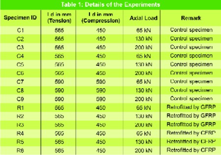
Static tests were conducted on the control and retrofitted reinforced concrete beam-column joint specimens. Generally, when the axial load on the column exceeds 50 to 60% of its capacity, the effect of axial load will be more predominant on the joint. But in the case of the seismic forces, the effect of lateral load will be more predominant. Hence in order to truly reflect the performance of the joint under seismic load conditions, it was decided to restrict the axial loads of column to a maximum of 200 kN which is less than 50 % of load carrying capacity of the column. The experimental investigation consisted of applying three axial loads of 65 kN, 130 kN and 200 kN on the columns and applying a point load at the free end of the cantilever beam portion till the failure of the specimen. The loading was continued till the joint failed by crushing of concrete in the case of control specimens and rupture of wrap in the case of retrofitted specimens. The details of the experiments are given in Table 1
Garbon fiber reinforced polymer wrap (GFRP) was used to strengthen the three failed beam-column joint specimens C1,C2 & C3 and they are redesignated as retrofitted specimens R1, R2 & R3. Carbon fiber reinforced polymer wrap (CFRP) was used to strengthen the other three failed beam-column joint specimens C4,C5 & C6 and they are redesignated as retrofitted specimens R4, R5 & R6.They were again tested to failure. The performance of the retrofitted beam-column joint specimens was compared with that of the control beam-column joint specimens.
A hand roller was then applied gently over the wrap so that good adhesion was achieved between the concrete surface and the GFRP or CFRP wrap, as suggested by the manufacturers and allowed to cure for seven days. Another coat of the two component epoxy was applied over the fiber sheet. Then the second wrap was applied by following the same procedure and allowed to cure for a further period of seven days. Both the wrapped layers were orthogonal to each other.
In the case of the specimen C2, first crack was formed in the beam portion approximately at a distance of 50 mm from face of the column at a load of 5 kN. At a load of 10 kN, another crack was formed in the beam-column joint of the test specimen. The cracks in the beam started to widen at a load of 15 kN. Spalling of concrete occurred in the tension zone of the beam at a load of 18.5 kN. The application of the load was stopped when the deflection at the free end of the beam reached 50 mm. The load corresponding to this deflection was 20 kN.
In the case of the specimen C3, the first crack was formed in the beam portion approximately at a distance of 45 mm from face of the column at a load of 4.75kN. At a load of 10.5 kN, cracks propagated to the compression zone of the beam. Spalling of concrete occurred in the beam at a load of 14.5 kN. Cracks propagated to the beam-column joint portion at a load of 18 kN. The application of the load was stopped when the deflection at the free end of the beam reached 50 mm. The load corresponding to this deflection was 18 kN.
In the case of the specimen C4, first crack was formed in the beam portion approximately at a distance of 40 mm from face of the column at a load of 4.25 kN. At a load of 10.5 kN, cracks propagated to the compression zone of the beam. Spalling of concrete occurred in the beam at a load of 13.5 kN. Cracks propagated to the beam-column joint portion at a load of 17.5 kN. The application of the load was stopped when the deflection at the free end of the beam reached 45 mm. The load corresponding to this deflection was 19.5 kN.
In the case of the specimen C5 first crack was formed in the beam portion approximately at a distance of 55 mm from face of the column at a load of 5.5 kN. At a load of 10.25 kN, another crack was formed in the beam-column joint of the test specimen. The cracks in the beam started to widen at a load of 15.25 kN. Spalling of concrete occurred in the tension zone of the beam at a load of 18 kN. The application of the load was stopped when the deflection at the free end of the beam reached 50 mm. The load corresponding to this deflection was 19.75 kN.
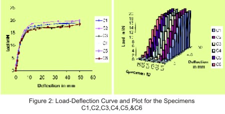
In the case of the specimen C6 the first crack was formed in the beam portion approximately at a distance of 42 mm from face of the column at a load of 4.5 kN. At a load of 10 kN, cracks propagated to the compression zone of the beam. Spalling of concrete occurred in the beam at a load of 14 kN. Cracks propagated to the beam-column joint portion at a load of 17.5 kN. The application of the load was stopped when the deflection at the free end of the beam reached 45 mm. The load corresponding to this deflection was 18.5 kN. The load deflection curves for these specimens are shown in Figure 2 .The load carrying capacity of the all six controlled specimens are given in Table 2.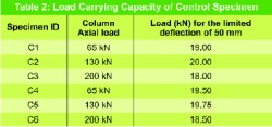 In the case of the retrofitted specimen R1 (GFRP), first crack was formed in the beam portion very close to the column at a load of 10 kN. At a load of 13 kN, a crack propagated to the compression zone of the beam. The cracks in the beam started to widen at a load of 19 kN and bond failure of the wrap was noticed on the tension side of the beam at a distance of 50 mm from the face of the column. The application of the load was stopped when the deflection at the free end of the beam reached 50 mm. The load corresponding to this deflection was 25.5 kN.
In the case of the specimen R2 (GFRP), first crack was formed in the beam portion at a distance of 30 mm from the face of the column at a load of 11 kN kN. At a load of 14.5 kN, the crack propagated to the compression zone of the beam. The cracks propagated into the column portion at a load of 19 kN. Bond failure of the wrap was noticed on the tension side of the beam at a load of 21 kN and the compression side of the beam at a load of 25 kN. The application of the load was stopped when the deflection at the free end of the beam reached 50 mm. The load corresponding to this deflection was 27 kN.
 In the case of the specimen R3 (GFRP), the first crack formed in the beam portion at a load of 11 kN. Bond failure of the wrap was noticed on the tension side of the beam at a load of 15 kN and on the tension side of the compression side of the beam at a load of 20 kN. The application of the load was stopped when the deflection at the free end of the beam reached 50 mm. The load corresponding to this deflection was 26.5 kN.
In the case of the retrofitted specimen R4 (CFRP) first crack was formed in the beam portion very close to the column at a load of 12kN. At a load of 15 kN, a crack propagated to the compression zone of the beam. The cracks in the beam started to widen at a load of 21kN and bond failure of the wrap was noticed on the tension side of the beam at a distance of 50 mm from the face of the column. The application of the load was stopped when the deflection at the free end of the beam reached 50 mm. The load corresponding to this deflection was 26.8 kN.
In the case of the specimen R5 (CFRP), first crack was formed in the beam portion at a distance of 30 mm from the face of the column at a load of 12.5 kN. At a load of 16 kN, the crack propagated to the compression zone of the beam. The cracks propagated into the column portion at a load of 20 kN. Bond failure of the wrap was noticed on the tension side of the beam at a load of 22 kN and the compression side of the beam at a load of 26 kN. The application of the load was stopped when the deflection at the free end of the beam reached 50 mm. The load corresponding to this deflection was 27.5 kN.
In the case of the specimen R6 (CFRP), the first crack formed in the beam portion at a load of 12 kN. Bond failure of the wrap was noticed on the tension side of the beam at a load of 15.5 kN and on the tension side of the compression side of the beam at a load of 21 kN. The application of the load was stopped when the deflection at the free end of the beam reached 50 mm. The load corresponding to this deflection was 27 kN.
In the last few decades, moderate and severe earthquakes have struck different places in the world, causing severe damage to reinforced concrete (RC) structures. Retrofitting of existing structures is one of the major challenges that modern civil engineers have to face. Recent evaluation of civil engineering structures has demonstrated that most of them will need major repairs in the near future. Upgradation to higher seismic zones of several cities and towns in the country has also necessitated in evolving new retrofitting strategies.
One of the techniques of strengthening of the RC structural members is through confinement with a composite enclosure. This external confinement of concrete by high strength fiber reinforced polymer (FRP) composites can significantly enhance the strength and ductility and will result in large energy absorption capacity of structural members. FRP materials, which are available in the form of sheets, are being used to strengthen a variety of RC elements to enhance the flexural, shear, and axial load carrying capacity of these elements.
Beam-column joints, being the lateral and vertical load resisting members in RC structures are particularly vulnerable to failures during earthquakes and hence strengthening of the joints is often the key to successful seismic retrofit strategy. In this paper an attempt has been made to study the influence of development length in reinforced concrete beam-column joints retrofitted with Carbon fiber reinforced polymer wrap and Glass fiber reinforced polymer wrap.
Nine RC beam-column joint specimens (control) were cast and tested to failure during the present investigation. In six specimens, the development length of the beam rods were provided as per IS 456. In remaining three specimens, the development length of the beam rods were provided as per IS 13920. The failed beam-column joint specimens were retrofitted by removing the concrete in the joint portion and recasting with concrete of the same grade and subsequently wrapping of Carbon fiber reinforced polymer (CFRP) sheets. These sheets were used to wrap three specimens and Glass fiber reinforced polymer (GFRP) sheets were used to strengthen the other three specimens. The performance of the retrofitted beam-column joints was compared with the control beam-column joint specimens and the results are presented in this paper.
Introduction
Recent earthquakes have exposed the vulnerability of existing reinforced concrete (RC) beam-column joints to seismic loading. Until early 1990s, concrete jacketing and steel jacketing were the two common methods adopted for strengthening the deficient RC beam-column joints. Concrete jacketing results in substantial increase in the cross sectional area and self-weight of the structure. Steel jackets are poor in resisting weather attacks. Both methods are however labour intensive and sometimes difficult to implement at the site. A new technique has emerged recently which uses fiber reinforced polymer sheets to strengthen the beam-column joints. FRP materials have a number of favorable characteristics such as ease to install, immunity to corrosion, high strength, availability in sheets etc., The simplest way to strengthen such joints is to attach FRP sheets in the joint region in two orthogonal directions.The initial developments of the FRP strengthening technique took place in Germany and Switzerland. Strengthening of reinforced concrete members with externally wrapped FRP laminates by Carbon and Glass FRP sheets has been studied in detail by researchers at Swiss Federal Laboratories for Materials Testing and Research, German Institute of Structural Materials and Institute for Building Construction & Fire Protection. The results obtained proved that the FRP strengthening technique is highly efficient and effective.
Literature Review
Geng et al (1998) used composite overlays to strengthen simple models of interior beam-column joints, which resulted in increase the strength of joints including stiffness and ductility of the specimens.Ze-Jun Geng et al (1998) investigated the effect of strengthening of beam-column connection with CFRP sheets wrapped around the joint with a set of steel angles and rods. They reported that retrofitting has resulted in significant improvement in ductility. The ultimate load carrying capacity was also found to increase by 35 %.
Prota et al (2000) have focused on a new technique for the seismic upgradation of RC beam-column connections in gravity load-design frames by the application of FRP rods and laminates. The FRP rods provided flexural strengthening, whereas the lay-up laminates provided confinement and shear strengthening. Along with modeling of such upgraded connections to assess the increase of strength and ductility provided by the composite reinforcement, an experimental program was also carried out by them.
Jianchun Li et al (2002) developed a model for a concrete column–beam connection with fiber reinforced polymer (FRP) reinforcement. Results of the analysis indicated that designed FRP reinforcement greatly improved the stiffness and load carrying capacity of its concrete counterpart. It also delayed the crack initiation at the joint.
D’Ayala et al (2003) have reported the results of cyc1ic tests carried out on beam-column joint specimens strengthened by externally bonded FRP fabric. The specimens tested by them were designed to comply with gravity load design codes and seismic design was not considered.
Kabir et al (2003) investigated the upgradation of a RC joint against reversal loading, which represents seismic excitation. It was reported that the use of composite fabrics enhanced the performance of the joint. The load-deflection curves for strengthened beam-column connections were studied in detail. They also reported that the behavior of retrofitted joints such as moment bearing capacity, ductility, axial load and drift was significantly improved.
Based on the review of literature it is found that only few experimental investigations have been carried out on beam-column joints. Hence an attempt has been made to carry out an investigation on beam-column joint specimens retrofitted with glass and carbon FRP wrap.
Experimental Investigations
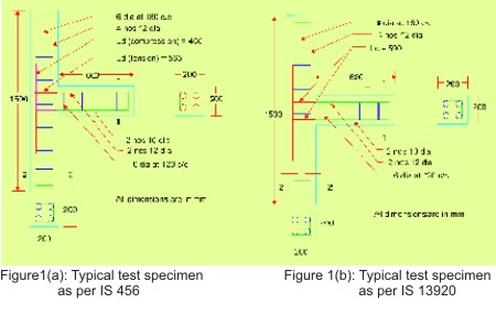
The experimental program consisted of testing nine reinforced concrete beam-column joint specimens. The details of a typical test specimens are given in Fig.1(a) & Fig.1(b). The column had a cross section of 200 mm x 200 mm with an overall length of 1500 mm and the beam had a cross section of 200 mm x 200 mm with a cantilevered portion of length 600 mm. For six specimens, the development length of the tension and compression rods in beam was provided as per clause 26.2.1 of IS 456. For the remaining three specimens, the development length of the beam rods was provided as per clause 6.2.5 of IS 13920. The concrete mix was designed for a target strength of 20 MPa at the age of 28 days. The load carrying capacity of the column was found to be 440 kN as per the code IS 456-2000.Static tests were conducted on the control and retrofitted reinforced concrete beam-column joint specimens. Generally, when the axial load on the column exceeds 50 to 60% of its capacity, the effect of axial load will be more predominant on the joint. But in the case of the seismic forces, the effect of lateral load will be more predominant. Hence in order to truly reflect the performance of the joint under seismic load conditions, it was decided to restrict the axial loads of column to a maximum of 200 kN which is less than 50 % of load carrying capacity of the column. The experimental investigation consisted of applying three axial loads of 65 kN, 130 kN and 200 kN on the columns and applying a point load at the free end of the cantilever beam portion till the failure of the specimen. The loading was continued till the joint failed by crushing of concrete in the case of control specimens and rupture of wrap in the case of retrofitted specimens. The details of the experiments are given in Table 1
Garbon fiber reinforced polymer wrap (GFRP) was used to strengthen the three failed beam-column joint specimens C1,C2 & C3 and they are redesignated as retrofitted specimens R1, R2 & R3. Carbon fiber reinforced polymer wrap (CFRP) was used to strengthen the other three failed beam-column joint specimens C4,C5 & C6 and they are redesignated as retrofitted specimens R4, R5 & R6.They were again tested to failure. The performance of the retrofitted beam-column joint specimens was compared with that of the control beam-column joint specimens.
Preparation of Test Specimens
The RC beam-column joint specimens were cast using fabricated steel moulds. Reinforcement was prepared and placed inside the mould. The grade of concrete used was M20. Concrete was mixed in a tilting type mixer machine. Care was taken to see that concrete was properly placed and compacted. The sides of the mould were removed 24 hours after casting and the test specimens were cured in water for 28 days.Preparation of the Retrofitted Specimens
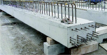
The failed specimens C1, C2, C3 & C4,C5 ,C6 were retrofitted and redesignated as specimens R1, R2, R3 & R4, R5, R6 . The concrete near the area of failure was removed completely. After applying cement paste in this area, the portion was filled and compacted with the same grade of concrete. The specimens were cured for 28 days. Before wrapping the GFRP, CFRP sheets, the faces of the specimens were ground mechanically to remove any laitance. All the voids were filled with putty. Then a two component primer system was applied on the concrete surface and allowed to cure for 24 hours. A two component epoxy coating was then applied on the primer coated surface and the GFRP or CFRP sheet was immediately wrapped over the entire surface of the reinforced concrete beam-column joint.A hand roller was then applied gently over the wrap so that good adhesion was achieved between the concrete surface and the GFRP or CFRP wrap, as suggested by the manufacturers and allowed to cure for seven days. Another coat of the two component epoxy was applied over the fiber sheet. Then the second wrap was applied by following the same procedure and allowed to cure for a further period of seven days. Both the wrapped layers were orthogonal to each other.
Description of the Test Programme
The specimen C1,C4 & C7 were tested in a loading frame in the horizontal plane. Both the ends of the column were hinged using roller plates. The axial load of 65 kN was applied at one end the column using a hydraulic jack of 250kN capacity and the load was measured using an electrical load cell. The other end of the column was supported by the steel bulkhead attached to the loading frame. A transverse load was applied at the free end of the beam through a hydraulic jack of capacity 100 kN at a distance of 600 mm from the column face to develop a bending moment at the joint. The load on the beam was also measured using an electrical load cell. The deflection at the free end of the beam was recorded at regular load intervals. The specimens C2,C5,C8 and C3,C6,C9 were tested in the same way and the axial loads applied on these specimens were 130 kN and 200 kN respectively. The retrofitted specimens R1&R4, R2&R5 and R3&R6 were also tested for the axial loads of 65kN, 130kN and 200kNAnalysis of the Results
In the case of the specimen C1, first crack was formed in the beam portion approximately at a distance of 45 mm from face of the column at a load of 4.5 kN. At a load of 11 kN, cracks propagated to the compression zone of the beam. Spalling of concrete occurred in the beam at a load of 14 kN. Cracks propagated to the beam-column joint portion at a load of 18 kN. The application of the load was stopped when the deflection at the free end of the beam reached 50 mm. The load corresponding to this deflection was 19 kN.In the case of the specimen C2, first crack was formed in the beam portion approximately at a distance of 50 mm from face of the column at a load of 5 kN. At a load of 10 kN, another crack was formed in the beam-column joint of the test specimen. The cracks in the beam started to widen at a load of 15 kN. Spalling of concrete occurred in the tension zone of the beam at a load of 18.5 kN. The application of the load was stopped when the deflection at the free end of the beam reached 50 mm. The load corresponding to this deflection was 20 kN.
In the case of the specimen C3, the first crack was formed in the beam portion approximately at a distance of 45 mm from face of the column at a load of 4.75kN. At a load of 10.5 kN, cracks propagated to the compression zone of the beam. Spalling of concrete occurred in the beam at a load of 14.5 kN. Cracks propagated to the beam-column joint portion at a load of 18 kN. The application of the load was stopped when the deflection at the free end of the beam reached 50 mm. The load corresponding to this deflection was 18 kN.
In the case of the specimen C4, first crack was formed in the beam portion approximately at a distance of 40 mm from face of the column at a load of 4.25 kN. At a load of 10.5 kN, cracks propagated to the compression zone of the beam. Spalling of concrete occurred in the beam at a load of 13.5 kN. Cracks propagated to the beam-column joint portion at a load of 17.5 kN. The application of the load was stopped when the deflection at the free end of the beam reached 45 mm. The load corresponding to this deflection was 19.5 kN.
In the case of the specimen C5 first crack was formed in the beam portion approximately at a distance of 55 mm from face of the column at a load of 5.5 kN. At a load of 10.25 kN, another crack was formed in the beam-column joint of the test specimen. The cracks in the beam started to widen at a load of 15.25 kN. Spalling of concrete occurred in the tension zone of the beam at a load of 18 kN. The application of the load was stopped when the deflection at the free end of the beam reached 50 mm. The load corresponding to this deflection was 19.75 kN.
In the case of the specimen C6 the first crack was formed in the beam portion approximately at a distance of 42 mm from face of the column at a load of 4.5 kN. At a load of 10 kN, cracks propagated to the compression zone of the beam. Spalling of concrete occurred in the beam at a load of 14 kN. Cracks propagated to the beam-column joint portion at a load of 17.5 kN. The application of the load was stopped when the deflection at the free end of the beam reached 45 mm. The load corresponding to this deflection was 18.5 kN. The load deflection curves for these specimens are shown in Figure 2 .The load carrying capacity of the all six controlled specimens are given in Table 2.
Effect of Axial Load on Column
It is seen from Table 2. that the effect of axial load on column is negligible in altering the load carrying capacity of the beam. There is not much difference in the load deformation characteristics of the beam-column joint specimens with an increase in the axial load. In the case of control specimens, cracks emanated from the beam portion and with an increase in the load, the cracks propagated into the joint portion of the specimens and spalling of concrete was noticed.Retrofitted Specimens
In the case of the specimen R2 (GFRP), first crack was formed in the beam portion at a distance of 30 mm from the face of the column at a load of 11 kN kN. At a load of 14.5 kN, the crack propagated to the compression zone of the beam. The cracks propagated into the column portion at a load of 19 kN. Bond failure of the wrap was noticed on the tension side of the beam at a load of 21 kN and the compression side of the beam at a load of 25 kN. The application of the load was stopped when the deflection at the free end of the beam reached 50 mm. The load corresponding to this deflection was 27 kN.
In the case of the retrofitted specimen R4 (CFRP) first crack was formed in the beam portion very close to the column at a load of 12kN. At a load of 15 kN, a crack propagated to the compression zone of the beam. The cracks in the beam started to widen at a load of 21kN and bond failure of the wrap was noticed on the tension side of the beam at a distance of 50 mm from the face of the column. The application of the load was stopped when the deflection at the free end of the beam reached 50 mm. The load corresponding to this deflection was 26.8 kN.
In the case of the specimen R5 (CFRP), first crack was formed in the beam portion at a distance of 30 mm from the face of the column at a load of 12.5 kN. At a load of 16 kN, the crack propagated to the compression zone of the beam. The cracks propagated into the column portion at a load of 20 kN. Bond failure of the wrap was noticed on the tension side of the beam at a load of 22 kN and the compression side of the beam at a load of 26 kN. The application of the load was stopped when the deflection at the free end of the beam reached 50 mm. The load corresponding to this deflection was 27.5 kN.
In the case of the specimen R6 (CFRP), the first crack formed in the beam portion at a load of 12 kN. Bond failure of the wrap was noticed on the tension side of the beam at a load of 15.5 kN and on the tension side of the compression side of the beam at a load of 21 kN. The application of the load was stopped when the deflection at the free end of the beam reached 50 mm. The load corresponding to this deflection was 27 kN.
Effect of Retrofitting
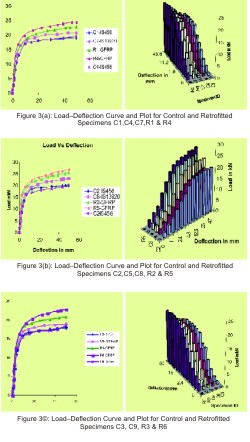
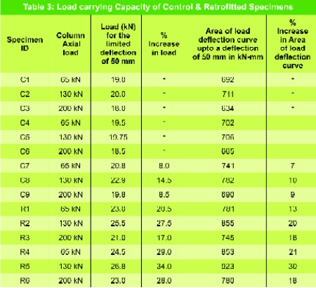
The load deflection plots of GFRP or CFRP wrapped and control RC beam-column joint specimens for various column axial loads are shown in Fig.3(a).Fig.3(b) and Fig.3(c). The load carrying capacity of the various reinforced concrete beam-column joint specimens (both control and retrofitted) are given in Table 3. It is seen from the Table 3. that the load carrying capacity of specimen retrofitted with GFRP has increased in the range of 17 % to 27 % and the area of the load deflection curve up to a deflection of 50 mm for specimens retrofitted with GFRP was 13 % to 20 % more compared to the control specimens. It is also seen that the load carrying capacity of specimen retrofitted with CFRP has increased in the range of 28 % to 34 % and the load deflection curve up to a deflection of 50 mm for specimens retrofitted with CFRP 18 % to 30 % more compared to the control specimens. The load deformation characteristics also improved to a larger extent in the case of wrapped specimens over the control specimens. This resulted in a substantial increase in the energy absorption characteristics of the specimens that were wrapped with GFRP or CFRP.Conclusions
Based on the experimental investigations carried out on the control and GFRP or CFRP wrapped beam-column joint specimens, the following conclusions are drawn:- The effect of axial load on the performance of beam-column joints is found to be negligible.
- There is 14.5 % increase in the load capacity and 10 % increase in energy absorption capacity of the RC beam-column joint specimen, as the development length is increased based on IS 13920.
- The percentage increase in the load carrying capacity of the retrofitted specimens was found to be in the range of 17 %-34 %.
- The load deformation characteristics also improved to a larger extent in the case of the retrofitted specimens over the control specimens. This resulted in a substantial increase in the energy absorption characteristics of the specimens that were retrofitted with GFRP or CFRP.
- The enhancement in the energy absorption capacity of the wrapped specimens was in the range 18%-30% over the control beam-column joint specimens.
- The failure was in the column portion of the joint for the control specimen which is to be avoided. In the case of the wrapped specimens, the failure was noticed in the beam portion only and the column was intact and this is the most preferred type of failure under seismic loads which will prevent progressive collapse of the structure.
References
- Geng et al (1998) and Mosallam (1999), “Seismic repair and upgrade of structural capacity of reinforced concrete connections: Another opportunity for polymer composites” Proc., int. composites expo ’99, Cincinati, ppl-8.
- Ze-Jun Geng, Michael J Chajes, Tsu-Wei Chouc & David Yen-Cheng Pand. (1998), “The retrofitting of reinforced concrete column to beam connections.” Composites science and technology, 58, pp 1297-1305.
- Prota,A., Nanni,A., Manfredi,G. Nd Cosenza,E.,(2000), “Models of concrete confined by fiber composites,” Proceedings of the fifth international conference of fiber reinforced concrete structures (FRPRCS 5), PP 865-874.
- Jianchun li, A., Bijan Samali, Lin Ye,Steve Bakoss.,(2002), “Behavior of concrete beam-column connections reinforced with hybrid FRP sheet,” Composite structures,57,pp 357-365.
- D’Ayala, D., Penford,A., and Valentini,S., (2003), “Use of FRP fabric for strengthening of reinforced concrete beam column joint,” Journal of composite for construction,2(4),pp 165-174.
- Kabir,M.Z., Ashrafi,H.R and Varzaneh,M.N., (2003), “Upgrading ductility of RC beam-column connection with high performance FRP laminates,” Damage and fracture mechanics VII, CA Brebbia & SI Nishdia (Editors) ISBN 1-85312-926-7.
Published on:
15 April 2009
Published in: NBM&CW April 2009
Share:
We Value Your Comment