Concrete for Tall Residential and Composite Office Buildings
Joseph P. Colaco, President, CBM Engineers, Inc. TX USA
Concrete for New Age Structures especially for tall buildings, concrete has major advantages – it is economical, fire-proof, has lower floor-to-floor heights, higher damping values and higher stiffness. All these are reasons that all the recent tall office buildings are composite (steel and concrete) structures and all the recent residential buildings are pure concrete structures.
Introduction

There are many tall residential towers planned and under construction mostly in Dubai, Mumbai, and in China. The height of these towers range from 30 to 40 stories at the lower end and at the upper end to the world’s tallest tower, the Burj Dubai, (Fig. 1), currently under construction. These tall residential towers have given rise to the need for new structural systems and the adaptation of existing structural systems from tall office towers.
Many of the tall office buildings in the world such as the Shanghai Financial Centre, Taipei 100 and Petronas Towers are all composite steel/concrete structures.
Structural Systems
So far, most of tall residential towers are being constructed in reinforced concrete. The advantages of concrete such as lower cost, faster speed of construction, ease of finishing, fire-proof characteristics and structural stiffness are well known. Moreover, concrete technology is very advanced. Because of the height of the buildings and the desirability of limiting the column sizes, concrete strengths have also increased. Currently, in Dubai, for lower columns and shear walls, C80 concrete is being used routinely and C90 and C100 concrete strengths have been considered. Normal weight concrete is used for all structural elements. In Mumbai, M70 concrete is being used. The collateral benefit of higher concrete strengths is the increase in the modulus of elasticity and earlier stripping times. Currently a 4 to 5-day cycle per typical floor is being achieved.
In Tall Residential Towers, it is desirable to have minimum reduction of outside views from the interior of the floor. One possibility is the use of interior demising walls and shear walls. Framed tubes give less than 50% (in some cases 30%) exterior glass. It was therefore necessary to evolve different systems for Tall Residential Towers
The systems that are developed are:
- Full Width Systems – Where the concrete shear walls run through the entire width of the building with minimum openings. While these walls are possible in the apartment floors, they are generally very difficult to accommodate in lobbies and parking areas.
- Core walls with outriggers – Core shear walls with one or two story deep outrigger beams connecting to exterior columns at discrete levels. These outriggers are most advantageous between one-third and two-third of the height.
- Spine walls with outriggers – Walls that are placed at interior corridor walls with door openings. Outrigger beams connect to exterior columns and are placed usually at service floors.
One of the design considerations for tall apartment towers is the restriction of the motion perception in the ISO guidelines. In general for a 10-year storm the acceleration is restricted to 1.5 to 1.8% G where G is the gravity acceleration. These values are lower than those for an office tower. One year and 5 year storms are also a consideration.
A brief description of key projects will illustrate the point.
A. Burj Dubai

Fig. 1 shows the typical floor plan of the tower designed by Skidmore, Owings and Merrill. The structural system is a triangular core shear wall “buttressed” by 3 double walls along the corridors of each leg of the plan. The floor slab is a 200mm flat plate mild steel reinforced. An elevation of the tower is shown in Fig.2. Extensive wind tunnel tests were run using two laboratories. Calculations of shrinkage and creep of vertical elements were done to develop a differential axial shortening matrix. Moreover, an extensive prototype test was run to measure the deflection (short-term and long-term) for the deflection of the 200 mm. floor slab.
B. Princess Tower

This is a 102-story tall tower in the Dubai Marina. Fig. 3 shows the typical floor plan. The lateral load resisting system is a perimeter “framed tube” system. The exterior columns are closely spaced and the spandrel beams are 1.2m deep. The core wall has very little effect on the overall behavior under lateral loads except at the bottom of the building. The floor system consists of steel floor beams, 60 mm deep metal deck and 90 mm concrete slab. The main reason for the structural steel floor framing was to reduce the weight of the building because of foundation capacity restrictions. An elevation of the building is shown in Fig. 4. A wind tunnel test was done both for cladding pressures and dynamic behavior of the structure. A tuned-sloshing damper is being considered.
C. Elite Tower

This is a 90-story tall tower in the Dubai Marina. A typical floor plan is shown in Fig. 5. Once again a perimeter framed tube with a core shear wall is used for lateral resistance. The core wall is primarily a vertical load resisting element in the upper floors. A cross-wall system (not shown) is used in one direction up to the 29th floor. The floor framing is a 200 mm thick concrete post-tensioned flat slab with a portion around the core wall thickened to 350mm. This system eliminates all interior columns. The architectural advantages of a column-free space are obvious. Structurally, it increases the gravity loads on the exterior columns and minimizes uplift. The elevation of the tower is show in Fig. 6. A wind tunnel test utilized a 2% damping ratio and no extra damping is required to meet ISO guidelines.
D. Hircon Tower

This is a 72-story tall octagonal tower in the Dubai Marina designed by Indian Architect, Hafeez Contractor. The structural system is shown in Fig. 7 and the elevation in Fig. 8. The lateral load resisting system consists of a core shear wall in one direction and a “full-width” concrete wall in the other direction. The perimeter columns are widely spaced and a flat “band beam” 450 mm deep is used as a spandrel beam. The floor slab is a 240 mm concrete flat plate. The upper floors have internal swimming pools within the apartments. No external damping is required.
E. Palais Royale, Mumbai
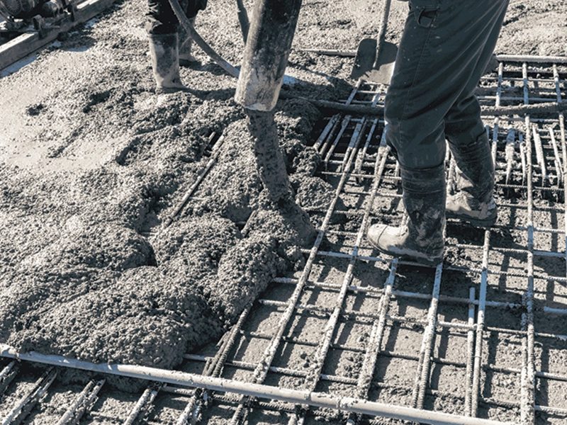
This is a 300 m. tall apartment tower currently under construction in Mumbai. One half of the floor plan is shown in Fig. 9 and the elevation is shown in Fig. 10. The building is octagonal in plan and has a central atrium. There are shear walls around the elevators. The floor system is a beam and slab system. A placement boom and MEVA formwork is also used as shown in Figs. 11 and 12.

Composite Structural Systems for Tall Office Buildings
The modern era of Composite Systems using both steel and concrete for columns began with the work of the late Dr. Fazlur Khan (1) in 1966. He thought that steel and concrete could be combined in the vertical plane just as efficiently as they had been in composite floor beams several decades earlier. His work led to construction of the first modern composite building, the 20-story Control Data Center in Houston in 1968. From a systems standpoint, the structure was constructed as a conventional steel frame except for the use of very small steel erection columns for the exterior columns. The steel frame was built approximately 8 floors ahead of the concrete placement in exterior columns and spandrel beams. The sequence of steel erection above, and concrete columns and spandrels below, was continued until the structure was topped out. Temporary bracing had to be used in the all-steel column portion of the structure until the concrete frame was completed. The resulting structure had an exterior composite frame that carried gravity loads and all the lateral loads. Several advantages were quickly recognized:

- The steel structure could be built at its normal speed.
- The concrete encasement of the exterior columns provided structural rigidity and fireproofing.
- The composite structure was economical.
For a detailed treatise on Composite Design of High Rise Buildings see Ref. 2.
J. P. Morgan Chase Plaza Houston.

Currently, the tallest composite building in North America is the 75-story, 300 m. tall, J. P. Morgan Chase Plaza Houston, which utilizes a composite column and concrete spandrel on the exterior. Both materials were used to their optimum, thereby producing cost savings and an entire new structural genre’ of building construction.
Figure 13 shows the typical floor plan. The exterior structure of the building has columns placed at 10’ (3m.) on centers on four sides but on the fifth side, there is a 85’ (26m.) clear span. The exterior columns are composite using a steel erection column and cast-in-place concrete. There is also a cast-in-place concrete 5’ (1.5m) deep spandrel beam at each level (see Figure 13). The interior columns and floor framing use structural steel. The foundation of the tower is a 9’-9" (3m.) thick concrete mat, 63’ (19.2m.) below grade. The exterior composite system, called a “ruptured-tube”, is the main element that is used to carry the wind loads on the structure. Since the closely spaced tube is ruptured at 85’ (26m.) clear span front face, the healing of the rupture was required. Several alternates were considered viz. providing diagonals across the front face to complete the “tube” or providing stiff truss elements at discrete floors to tie the ends of the front face together.

These alternates were discarded for aesthetic reasons. Hence, the only option was to use the building core. A concrete shear wall is placed next to the front row of elevators and the connection between the interior shear wall and the exterior tube is by very stiff steel link beams in the plane of the floor. There is a secondary stiffness elements consisting of a steel girder that spans 85’ (26m.) and ties the two triangular concrete front piers of the building. A photograph of the building under construction is shown in Figure 14.
For this tower a maximum 7,500 psi (52 MPa) 56-day strength normal weight concrete was utilized in exterior columns, spandrel beams, and shear wall from the mat foundation up to the 7th floor, and 6,000 psi (42Mpa) was utilized for these elements from the 8th to the 30th floors.
There are several advantages of high-strength concrete and they can be summarized as follows:
- Additional Stiffness: One of the considerations in tall buildings is the restriction of the inter-story drift under lateral loads. This is required in order to keep architectural elements from having any distress. Almost all tall building designs are controlled by stiffness requirements and hence, the use of high-strength concrete with its high modulus of elasticity results in a lower inter-story drift for the same member sizes. On this project, nominal 7,500 (52Mpa) concrete had a modulus of elasticity of approximately 5.7 x 10⁶ psi (39,330Mpa) which is substantially higher than that which is obtainable with 5,000 psi (35Mpa) concrete. The net result of this high E value is that the maximum deflection of the building under hurricane wind loads will not exceed 16" (41cm.) at the top of the building for wind in any direction.
- Damping; Extensive discussions were held with the University of Western Ontario that conducted the wind tunnel analysis for the project. Since the basic wind resisting elements are concrete members, the damping ratio was 2% whereas for an all-steel building, a 1% damping factor is generally used. This resulted in a much lower peak acceleration in the wind tunnel test. The building accelerations at the top floor of the building were in the range of 18 milli-g’s for a 10-year recurrence interval which is below the generally accepted criteria for the threshold of discomfort due to building motion.
- Axial Shortening: The differential movements of vertical elements in tall buildings are a critical item in the constructability of level floors (Ref. 3). In a composite frame, the problem is exacerbated by the fact that the interior columns of structural steel have only elastic axial shortening while the exterior composite columns are subjected not only to axial shortening due to stress but to shrinkage and creep. The use of high-strength concrete which has a higher modulus of elasticity reduces the axial shortening of the concrete columns. The use of limestone aggregate and the use of fly ash (which lowers cement content) reduce the shrinkage of the concrete columns. Axial shortening compensation tables were developed for the entire structure and interior steel column lengths were adjusted at 10-story increments to try to attain level floors. In the worst case, at the roof level the columns at the end of the 85’ clear span were placed 2.5 inches (6.3cm.) higher than the columns in the middle of the long faces.
References
- Khan, F. R., “Recent Structural Systems in Steel for High-Rise Buildings, Conference of Steel in Architecture, Bethlehem Steel No. 24 – 26, 1969.
- Viest, Colaco, Furlong, Griffis, Leon and Wyllie, “Composite Construction Design for Buildings, McGraw-Hill 1997.
- Fintel, Mark, Ghosh, S. K., and Iyengar, Hal, “Column Shortening in Tall Structures – Prediction and Compensation,” Portland Cement Association, Skokie, Illinois, 1987.
- Sheikh, T. M., Yura, J. A., and Jirsa, J. O. (1987), “Moment Connections Between Steel Beams and Concrete Columns, “PMFSEL Report NO. 87-4, The University of Texas, Austin, Texas.
- ACI-ASCE Committee 352, “Recommendations for Design of Beam-Column Joints in Monolithic Reinforced Concrete Structures”, Report ACI 352 R-85, 1985.
- ACI 318-89, “Building Code Requirements for Reinforced Concrete,” American Concrete Institute, Detroit, Michigan.