Comparison of Reinforced and Pre-Stressed Concrete Building Frames
This article discusses pre-stressing of concrete to get lighter and slender beam sections for six different four storied concrete building frames of different spans/lengths by the application of post-tensioning, and whether the use of post-tensioning reduces the volume of concrete used in the beams for small, medium and large spanned buildings. Optimized beam sections without pre-stressing forces are designed following Indian Code provisions using computational analysis. The design procedure satisfies both strength and serviceability criteria. Six building frames having different span lengths of three, six, ten, twelve, sixteen and twenty meters are designed. The loads are considered as per IS 875 part-2. The deflection obtained for the dead and live load is calculated and then neutralized by counteracting the load by introducing stress in concrete using post-tensioned force and section reduction. The optimization is done through subsequent iterations i.e. by simultaneous increments of pre-stressing force and reduction of section dimension.
Pre-stressing allows us to introduce internal stresses of a suitable magnitude and distribution so that the stresses resulting from external loads are counteracted to a desired degree. For reinforced concrete members, the pre-stresses are used either by introducing tension to the steel reinforcement itself, before pouring concrete-mix to the formwork also known as pre-tensioned concrete or by providing provisions for High tensile high yield steel wires, bar cables or strands used as tendons which are introduced to the section after the concrete has been casted and tension is given to the tendons which are released with proper anchorage to transmit the pre-stressing force to the concrete section as explained in Figure 1.
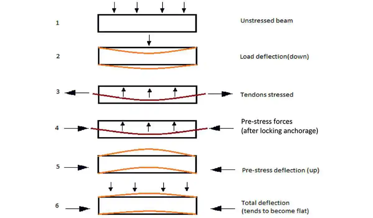 Figure 1: Concrete beam profile at different loading conditions during post-tensioning
The ducts providing tendon provisions (Figure 2) are then grouted. Generally high strength concrete (≥M40) is necessary as in anchorage zone, the bearing stress being higher; high-strength concrete is invariably preferred to minimize costs. High strength concrete is also less liable to shrinkage cracks, and has higher elastic modulus and smaller ultimate creep strain, resulting to smaller loss of pre-stress in steel.
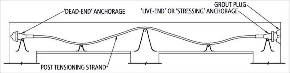 Figure 2: Duct layout for post-tensioning a beam
The uses of pre-stresses are spreading in all the construction fields namely bridges, tanks, pipes, marine, railway, etc. Thorough literature review shows substantial amount of work being done on pre-stressing in the last century. Development of a simplified flexural design method for partially pre-stressed concrete beams was done in the late twentieth century where the design procedure satisfied simultaneously both strength and serviceability criteria. This resulted in more efficient elements than those designed by the conventional approach using allowable working stress and then checking strength.
The purpose of the present study is to create six different optimized RCC building frames and check for further optimized frame structure when post-tensioning is used. The study is done to check whether there are any savings in concrete volume if the beams are pre-stressed instead of RCC. Six building frames are taken, each of which contains a four storied building frame; has three bays along its length as well as breadth. Each of the bays is of three meter, six meter, ten meter, twelve meter and sixteen meter length in their respective five cases. Other aims include the effectiveness of pre-stressing in reducing depth of beam, reduction in deflection due to loading cases and combinations and also to determine the role of pre-stressing as a cost efficient method in building construction.
Methodology
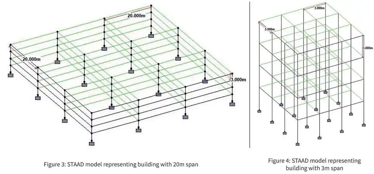
To achieve the goals, buildings of three span sizes (viz. small, medium and large) are considered. Firstly the RCC building is designed for the cases with the corresponding loads and M40 grade of concrete as defined in Table 1. The models are first checked for condition of collapse using STAAD.Pro V8i (select series 6) and the vertical maximum deflection at different members is noted. If the value of the maximum deflection at any member is greater than permissible value for concrete design (permissible: <L/250 or 20mm whichever is less; L in mm), the section is reassigned and the structure is redesigned. On obtaining an optimized frame structure for the six building frames, the section dimensions for beams and columns, volume of concrete consumed, percentage save in concrete and maximum compressive and tensile stress in the beams are noted.
Figures 3 and 4 represent the building frame model of 20m and 3m span length. Similar models were created by changing the span lengths according to the cases as defined in Table 1.
| Table 1: Data used for design and analysis of corresponding RCC and PSC building frames. | ||||||
| CASES DEPENDING ON SPAN SIZES | SL. NO. | LENGTH OF EACH SPAN | TOTAL LENGTH AND WIDTH OF BUILDING | CLEAR COVER (mm) | LOADS ACTING ON THE FRAME | FLOOR THICKNESS (m) |
| CASE I: SHORT SPAN |
1 | 3 METERS | 9 METERS | 35 | DEAD LOAD: Wall load = 10 kN/m, Floor load = 6 kN/m2 & Self weight of structure LIVE LOAD: Floor load = 4kN/m2 (1st to 3rd floor) and 2kN/m2 on roof |
0.150 |
| 2 | 6 METERS | 18 METERS | 35 | 0.175 | ||
| CASE II: MEDIUM SPAN |
3 | 10 METERS | 30 METERS | 50 | 0.200 | |
| 4 | 12 METERS | 36 METERS | 50 | 0.225 | ||
| CASE III: LARGE SPAN |
5 | 16 METERS | 48 METERS | 50 | 0.250 | |
| 6 | 20 METERS | 60 METERS | 50 | 0.300 | ||
Once all required data is extracted the design for post-tensioning is done. Depending on the span length pre-stressing forces are assigned to the beams. The post-tensioning force reduces the tension in the beams by inducing additional compression. Thus for the present work the dead load and live load is balanced by the pre-stressing force. Thus the maximum downward deflection obtained for the PSC section should be lesser than that obtained for RCC section, here taken as greater than or equal to zero. Thus by dropping the dead load by reducing the section dimension of beam and by increasing the value of pre-stress applied, the beam section is optimized to show zero maximum downward deflection or positive value for deflection that is the beams cambers up.
The stresses are monitored so they do not cross the compressive strength of concrete. Again the section dimensions for beams and columns, volume of concrete consumed, percentage save in concrete and maximum compressive and tensile stress at the beams are noted for comparison.
For the concrete design STAAD.Pro followed IS 456 code to check and design for the structures. Table 2 sums up the design parameters used for the analysis.
| Table 2: List of design parameters used for the building frame analysis | ||||
| SL. NO. | DESCRIPTION OF PARAMETER | SYMBOLS | VALUE | UNITS |
| 1 | Compressive strength of concrete | FC | 40000 | kN/m2 |
| 2 | Yield strength for main reinforcement | FYMAIN | 500000 | kN/m2 |
| 3 | Yield strength for shear reinforcement | FYSEC | 500000 | kN/m2 |
| 4 | Distance from surface of member to edge of outermost reinforcement | CLEAR | 0.035/0.05 | m |
| 5 | Max. % of longitudinal reinforcement allowed | RATIO | 3 | % |
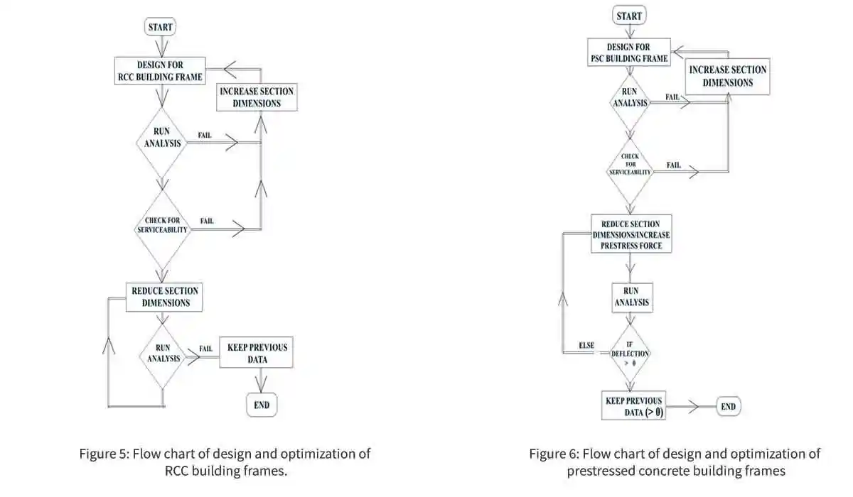
Figure 5 and Figure 6 contains flow-chart of the methodology for designing an optimized RCC and PSC frame of a certain building structure respectively.
Results
Following the above methodology, the results obtained are tabulated accordingly. Table 3 and Table 4 records the parameters like concrete take off, percentage of concrete saved and volume of concrete saved for comparison between RCC and PSC structure of Case I as mentioned in Table 1 i.e. building frames having span lengths of 3m and 6m are considered to be short span. Table 5 and Table 6 give the results for Case II i.e. for building frames of span lengths of 6m and 12m. Similarly, Table 7 and Table 8 give results for Case III for building frames of large span of 16m and 20m respectively. For PSC, the two ends of the cable profile are at the neutral axis of the beam section while the eccentricity of the midpoint is mentioned in the tables below.
a) CASE I - Small span:
| Table 3: Comparative study of RCC and PSC building frames with 3m span. | |||||||||||
| BUILDING FRAME WITH 3m SPANS | |||||||||||
| TYPE | FRAME STRUCTURE | MAX DEFLECTION (mm) | CONCRETE (m3) | MAX COMPRESSION (N/mm2) | MAX TENSION (N/mm2) | ECCENTR. (m) | BEAM DIM (mmXmm) | COLUMN DIM (mmXmm) | PSC FORCE (kN) | % CONCRETE save | CONC. SAVED (m3) |
| RCC | DL+LL | 4.707 down | 25.9 | 33.167 | -33.19 | 200X150 | 300X300 | NA | |||
| 1.383 down | |||||||||||
| PSC | DL+LL+POST | 2.801 up | 25.9 | 38.211 | -28.251 | -0.065 | 200X150 | 300X300 | 150 | 0 | 0 |
| 0.705 up | |||||||||||
| Table 4: Comparative study of RCC and PSC building frames with 6m span. | |||||||||||
| BUILDING FRAME WITH 6m SPANS | |||||||||||
| TYPE | FRAME STRUCTURE | MAX DEFLECTION (mm) | CONCRETE (m3) | MAX COMPRESSION (N/mm2) | MAX TENSION (N/mm2) | ECCENTR. (m) | BEAM DIM (mmXmm) | COLUMN DIM (mmXmm) | PSC FORCE (kN) | % CONCRETE save | CONC. SAVED (m3) |
| RCC | DL+LL | 8.75down | 90.7 | 33.38 | -33.44 | 450X450 | NA | ||||
| 2.877down | |||||||||||
| PSC | DL+LL+POST | 4.716up | 90.7 | 37.58 | -29.25 | -0.185 | 450X200 | 450X450 | 380 | 0 | 0 |
| 1.218up | |||||||||||
b) CASE II - Medium span:
| Table 5: Comparative study of RCC and PSC building frames with 10m span | |||||||||||
| BUILDING FRAME WITH 10m SPANS | |||||||||||
| TYPE | FRAME STRUCTURE | MAX DEFLECTION (mm) | CONCRETE ( m3) | MAX COMPRESSION (N/mm2) | MAX TENSION (N/m m2) | ECCENTR. (m) | BEAM DIM (mmXmm) | COLUMN DIM (mmXmm) | PSC FORCE (kN) | % CONCRETE save | CONC. SAVED ( m3) |
| RCC | DL+LL | 17.425down | 426.7 | 33.266 | -33.367 | 600X500 | 850X850 | NA | |||
| 6.862down | |||||||||||
| PSC | DL+LL+POST | 9.143up | 370.6 | 38.837 | -30.824 | -0.25 | 600X480 | 700X700 | 1175 | 13.15 | 56.1 |
| 2.714up | |||||||||||
| Table 6: Comparative study of RCC and PSC building frames with 12m span BUILDING FRAME WITH 12m SPANS | |||||||||||
| BUILDING FRAME WITH 12m SPANS | |||||||||||
| TYPE | FRAME STRUCTURE | MAX DEFLECTION (mm) | CONCRETE (m3) | MAX COMPRESSION (N/mm2) |
MAX TENSION (N/mm2) |
ECCENTR. (m) |
BEAM DIM (mmXmm) |
COLUMN DIM (mmXmm) |
PSC FORCE (kN) | % CONCRETE save |
CONC. SAVED (m3) |
| RCC | DL+LL | 15.599down | 726.2 | 27.258 | -27.38 | 800X600 | 950X950 | NA | |||
| 6.415down | |||||||||||
| PSC | DL+LL+POST | 11.036up | 638.7 | 38.109 | -30.328 | -0.3 | 700X620 | 850X850 | 1725 | 12.05 | 87.5 |
| 3.557up | |||||||||||
c) CASE III - Large span:
| Table 7: Comparative study of RCC and PSC building frames with 16m span | |||||||||||
| BUILDING FRAME WITH 16m SPANS | |||||||||||
| TYPE | FRAME STRUCTURE | MAX DEFLECTION (mm) | CONCRETE (m3) | MAX COMPRESSION (N/mm2) | MAX TENSION (N/mm2) | ECCENTR. (m) | BEAM DIM (mmXmm) | COLUMN DIM (mmXmm) | PSC FORCE (kN) | % CONCRETE save | CONC. SAVED (m3) |
| RCC | DL+LL | 19.59down | 1605.1 | 26.247 | -26.41 | 1100X800 | 1200X1100 | NA | |||
| 8.517down | |||||||||||
| PSC | DL+LL+POST | 15.002up | 1367.1 | 38.219 | -29.803 | -0.425 | 1000X725 | 1200X1100 | 3125 | 14.83 | 238 |
| 5.477up | |||||||||||
| Table 8: Comparative study of RCC and PSC building frames with 20m span | |||||||||||
| BUILDING FRAME WITH 20m SPANS | |||||||||||
| TYPE | FRAME STRUCTURE | MAX DEFLECTION (mm) | CONCRETE (m3) | MAX COMPRESSION (N/mm2) |
MAX TENSION (N/mm2) |
ECCENTR. (m) |
BEAM DIM (mmXmm) |
COLUMN DIM (mmXmm) |
PSC FORCE (kN) | % CONCRETE save |
CONC. SAVED (m3) |
| RCC | DL+LL | 19.291down | 3926.4 | 22.467 | -21.349 | 1400X1300 | 1500X1500 | NA | |||
| 9.436down | |||||||||||
| PSC | DL+LL+POST | 14.369up | 2702.2 | 37.751 | -30.919 | -0.55 | 1200X1000 | 1440X1440 | 4250 | 31.18 | 1224.2 |
| 5.139up | |||||||||||
*ECCENTR - Eccentricity of the midpoint of the parabolic cable profile from the Neutral Axis of the beam.
*up – upward deflection or positive value of deflection considering horizontal Neutral Axis as reference zero
*down – downward deflection or negative value of deflection considering horizontal Neutral Axis as reference zero
*DL+LL+POST – Dead Load + Live Load + Load due to Post Tensioning
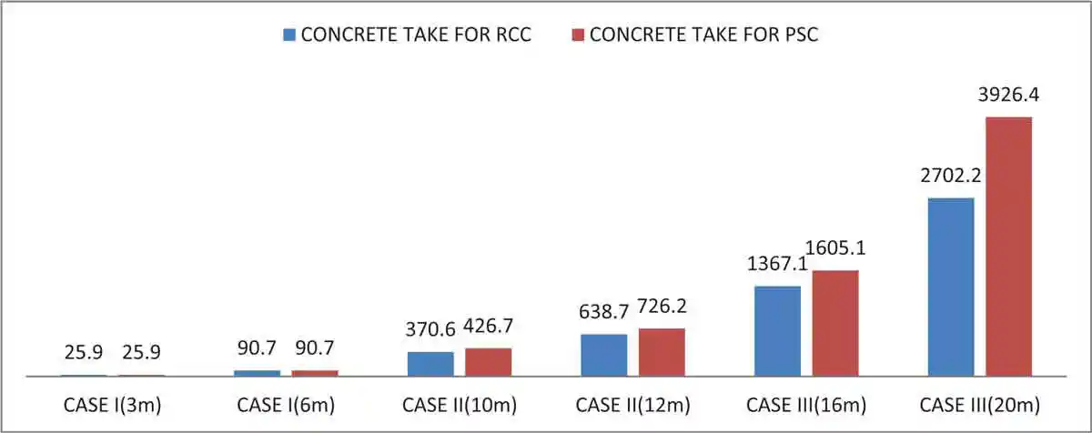 Figure 5: Concrete take off for different cases
Conclusions
From the above study, following conclusions about relevancy of use of PSC beams over RCC beams in a building frame, depending on their span lengths, can be drawn-
- For short span beams there is no possible scope for concrete savings and the use of PSC will not be a good choice.
- Medium span building frame with 10m span showed 13.15% of concrete saving as compared to RCC frame. Similarly building frame with 12m span showed 12.05% of concrete saving.
- Long span building frame with 16m span showed 14.83% of concrete saving as compared to RCC frame. Similarly building frame with 20m span showed 31.18% saving of concrete.
- IS 456-2000. Indian Standard Code of Practice for Reinforced Concrete (Fourth Revision)
- IS 1343-1980. Indian Standard Code of Practice for Pre-stressed Concrete (First Revision)
- N. Krishna Raju, Pre-stressed Concrete, IS: 1343-2012, BS EN: 1992-1-1-2004, ACI: 318M-2011. McGraw Hill Publication.1981
- Users’ Manual, STAAD.Pro, V8i (Select Series 6), Bentley
- V. Natarajan, Fundamentals of Pre-stressed Concrete. B. I. Publications.1983
Published on:
07 December 2020
Published in: NBM&CW December 2020
Share:
We Value Your Comment