Cementitious Composites with Steel Reinforcement
Response of Engineered Cementitious Composites with Steel Reinforcement and Concrete in Moment Resisting Frames
Dr. S. C. Patodi, Professor, J. D. Rathod, Applied Mechanics Department, Faculty of Technology & Engineering, M.S.University Baroda.
In the present work, the effects of cementitious composite ductility on the steel reinforced behavior are experimentally investigated and contrasted to the unreinforced composite. Interaction between ECC and concrete is observed and possibility of replacing ECC with concrete is explored. Tight crack width control in ECC is examined. L-type plane frame and portal frame specimens are used for the experimental investigation.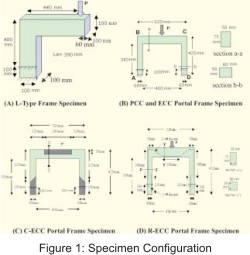 L-type plane frame specimens, 3 specimens each, were cast with plain cementitious matrix and ECC with 4% fiber. Portal frame specimens, 3 specimens each, were cast with plain cementitious matrix (PCC), ECC with 4% fiber, steel reinforced ECC (R-ECC), and combination of ECC and concrete (C-ECC). Specimen configuration of LFigure type frame and portal frame specimens is shown in Figure 1.
With the advent of new materials, there is a constant need for designers to find innovative ways to incorporate these materials into new applications. The field of civil engineering is currently at a cross roads of equal significance with development of new materials termed as High Performance Fiber Reinforced Cementitious Composites (HPFRCC). These materials with tensile performance magnitudes higher than Reinforced Concrete (R/ C), allow designers to create structures previously impossible due to limitations of minimum reinforcement, minimum clear cover or excessive cracking in R/C. The replacement of brittle concrete with an Engineered Cementitious Composite (ECC), which represents a class of HPFRCC, micro structurally tailored with strain hardening and multiple cracking properties, has shown to provide improved load-deformation characteristics in terms of reinforced composite tensile strength, deformation mode and energy absorption. This paper reports, investigation of response mechanism of composite moment resisting frame system with large energy dissipation capabilities. Plain cementitious matrix is used in frame specimens to estimate deformation behavior and formation of plastic hinges. Expected plastic hinge regions are properly detailed by steel reinforcement. Deformation mechanism of plain cementitious matrix suggested economic use of ECC by replacement with concrete in some areas. Load-displacement curves are plotted and compared for damage tolerance evaluation. Crack width is measured as a function of load for damage reduction evaluation and toughness index is found out for post peak performance evaluation. Compatibility of ECC with reinforcement and concrete in terms of deformation and strength is discussed.
Introduction
In earthquake resistant design, the structural system performance requirements can be specified in terms of minimum ductility ratio, number of load cycles, sequence of application of load cycles and permissible reduction in strength at the end of loading. At the beam column connection level, the following performances are desirable:- Ductile plastic hinge behavior under high shear stress,
- No congestion of transverse reinforcement for confinement and for shear,
- Concrete integrity under load reversals and
- Concrete damage contained within a relatively short hinging zone. These performances are difficult to achieve with ordinary concrete, although some encouraging results have been obtained with Fiber Reinforced Concrete (FRC)[1].
- High compression strain capacity to avoid loss of integrity by crushing,
- Low tensile first cracking strength to initiate damage within the plastic hinge,
- High shear and spall resistance to avoid integrity loss by diagonal fractures and
- Enhanced mechanism that increases inelastic energy dissipation. ECC is a class of ultra ductile fibre reinforced cementitious composite used to achieve above objectives without introducing ductile detailing in a structure. ECC can undergo upto 5% strain in tension, yet at the lower fibre volume of 2% with flexible processing. ECC can be used in some fused zones so that with the above performance, overall performance of the structure can be enhanced[2].
In the present work, the effects of cementitious composite ductility on the steel reinforced behavior are experimentally investigated and contrasted to the unreinforced composite. Interaction between ECC and concrete is observed and possibility of replacing ECC with concrete is explored. Tight crack width control in ECC is examined. L-type plane frame and portal frame specimens are used for the experimental investigation.
Material Composition
Recron 3S brand synthetic fibers of triangular cross section produced by Reliance Industries were used with cementitious matrix. Fiber volume fraction of 4% was used which was found as optimum fiber volume fraction by pilot tests. Kamal brand 53 grade OPC, 300 m passing silica sand, 2% dose of concrete super– plasticizer of conplast SP430 brand with w/c ratio as 0.35 and sand/cement ratio as 0.5 were used for the preparation of samples of ECC in the present experimental investigation. In addition, Kamal brand 53 grade OPC, silica sand confirming to zone III, 12.5 mm size coarse aggregates with w/c ratio of 0.35 and 0.5% dose of superplasticizer were used to produce concrete for use in combination with ECC in C-ECC specimens. Mix proportion for concrete used was 1:1.295:2.407. Mild steel reinforcement having yield strength of 250 N/mm2 was used in R-ECC specimen.Specimen Configuration
Experimental Programme
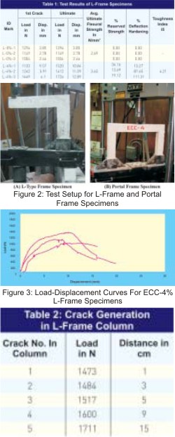
For the preparation of specimens, the ingredients in required proportion were mixed in Hobart type mixer machine. Flow table test was performed to satisfy workability criteria in fresh state. After filling the mould with the matrix, it was compacted and demoulded after 24 hours. All the specimens were kept in curing tank for 28 days at room temperature. After putting proper identification mark, specimens were fixed into prefabricated experimental set up on MTS machine. Basic Testware available on computer supervised controller was used to conduct the test. All the specimens were tested in flexure at a displacement control rate of 0.005 mm/sec. Load and displacement at the first crack and at ultimate load were recorded during the test. Loaddisplacement curves were plotted and data were automatically recorded using basic Testware data acquisition facility. Crack width was measured for the first initiated crack during the test with the help of travelling microscope having least count of 0.01 mm. Test setups for plane frame and portal frame specimens are shown in Figure 2.Discussion of Test Results
- L-type frame specimens were tested under flexure. First crack load and ultimate load results are reported in Table 1 for plain matrix (L-0%) and ECC with 4% (L-4%) fiber matrix. Reserved strength refers to increase in strength of the member upto ultimate load over the first crack strength. This criterion is used to represent residue strength of the material. Deflection hardening refers to increase in deflection of the member upto ultimate load over the first crack deflection. This value shows inelastic deformation capability of the member which represents ductility of the material. Plain matrix failed suddenly with no reserved strength and deflection hardening. ECC-4% matrix has load and displacement values higher than plain matrix. First crack displacement is almost 2 times and ultimate displacement is almost 3.5 times than plain cementitious matrix. There is marginal increase in reserved strength but considerable improved performance in deflection hardening over plain cementitious matrix is observed. Maximum deflection hardening achieved is more than 100%. Ultimate flexural strength of ECC-4% is found as 3.63 N/mm2 against 2.69 N/mm2 that of plain matrix.
- Load-displacement curves are plotted for all the three specimens of ECC-4% as shown in Figure 3. Strain hardening is observed in all the specimens with very little linear portion in the beginning.Toughness index I5 is calculated as area under the load displacement curve for 3 times first crack displacement divided by the area under load displacement curve for first crack displacement. Post peak performance of the material can be represented by this value, which is also indicative of energy absorption capacity of the material. Toughness index I5 for ECC- 4% specimen is found as 4.21 which for a plain matrix could not be represented as it failed suddenly after the formation of first crack.
- One can utilize design strength up to ultimate strength of ECC matrix in strain hardening zone. Development of cracks and crack width are therefore important in strain hardening zone. ECC matrix is well known for its tight crack width control which is utmost important for the durability of a member. One should make sure that migration of aggressive substances into matrix should be eliminated so that corrosion of reinforcement and subsequently spalling of matrix and delamination can be prevented. According to ACI committee 224, ultimate crack width should be limited to 150 μm when member is exposed to an environment of seawater and seawater spray in wetting and drying [4]. Rate of increase of crack width as a function of load gives information about consideration of design load for particular crack width criteria. Crack width was measured of the first visual crack and then crack width development with increase in load in the column of L- frame was recorded and was found within 150 μm at ultimate load.
- Crack generation history in the column of L frame is tabulated in Table 2 in which crack number along with its location from bottom of the beam is presented. Failure of L-type specimens took place due to rotation of column in the middle at crack number 4. First crack generated right below the bottom of the beam and subsequent cracks appeared below first crack with spacing of about 2 cm up to middle of the column as the load increased. Spacing of the cracks was more below the crack number 4. Number of crack formation with increase in load in the column of L–type specimen is shown in Figure 4.
- Portal frame specimens were tested under flexure to evaluate ECC performance along with combination of reinforcement and concrete. Strain hardening was not observed in plain cementitious matrix. First crack load and ultimate load of PCC, ECC, RECC and C-ECC frames are given in Table 3.
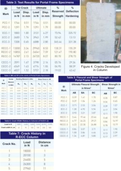
- Lower first crack strength and then large amount of plastic hinge formation is desirable for seismic response so as to have large energy dissipation. This behavior is reflected in ECC sample number 1 and 3. Sample number 3 of ECC-4% performed well in both and showed reserved strength as 365.44% and deflection hardening as 331.38% which is the maximum among ECC, R-ECC and C-ECC. In R-ECC samples nominal mild steel reinforcement of diameter 4 mm and 6 mm were used as shown in Figure 1(D). Shear reinforcement was not used looking to the enhanced shear capacity of ECC material. R-ECC specimens showed consistent enhanced performance with percentage reserved strength and percentage deflection hardening. Also, the deformation compatibility between ECC and reinforcement was observed.
- Concrete of compressive strength 58.89 N/mm2 [5] was used alongwith ECC matrix as per the plastic hinge formation and compression zone requirement in plain cementitious matrix. Replac–ement of ECC by concrete is indicated by dark portion in Figure 1(C). C-ECC specimens render economy in strength perfor– mance as is clear from the higher first crack and ultimate strength compare to ECC. Deformation compatibility between ECC and concrete and enhancement of strength perfor– mance after first crack is, however, questionable which can be observed from the poor results of percentage reserved strength and percentage deflection harde– ning. Bending moment and shear force at the base of column (AB), top ofcolumn (BA), and end of the beam (BC), along with bending moment at the center of the beam are calculated and tabulated in Table 4.
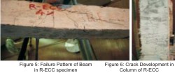
- Ultimate flexural strength and shear strength in PCC, ECC, RECC and C-ECC are calculated and tabulated in Table 5. Contribution of mild steel in flexure and associated consistent compatible deformation is highlighted in the result of R-ECC. Shear reinforcement is not provided in R-ECC specimen. Shear resistance is contributed by ECC material only. Ultimate shear strength of ECC material for ECC-4% is 7.51 N/mm2 [5] which is approximately double than M20 concrete. Calculated shear strength in sample number 1 is 12.02 N/mm2 which is higher than the ultimate shear strength of ECC. Therefore, shear failure of beam in R-ECC specimen is observed as shown in Figure 5.
- Crack width as a function of load was measured on the column of RECC sample number 2 and results are given in Table 6. Crack width remained 100 mm at a load of 19,494 N. Approximately, 20,000 N load is found to act for the threshold crack width of 150 μm. Structural element should be loaded corresponding to maximum permissible crack width of 150 μm from durability point of view. Development of the crack width upto 20,000 N load is slow but then it becomes fast.
- Development of crack width was also measured in beam of RECC sample number 3. There was a slow crack width development upto 20,833 N load but then suddenly it became fast. Approximately, 21,000 N causes crack width within limit of 150 μm.
- Crack development along with its location in the column from bottom of a beam for R-ECC was studied and is represented here in Figure 6 and Table 7. First crack initiated right at the bottom of the beam and new cracks generated below the first crack at approximately constant spacing with increase in load unlike ECC specimen.
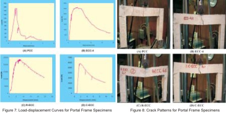
- Load displacement curves are plotted in Figure 7 for PCC, ECC-4, R-ECC and C-ECC specimens. PCC and CECC could not show strain hardening. ECC-4 specimen showed well defined strain hardening and post peak performance with less first crack load. R-ECC specimen performed the best with respect to strength, strain hardening and post peak behavior. Toughness indices are found out for ECC, R-ECC and C-ECC and tabulated in Table 8. As load displacement curve of ECC indicates the best post peak performance, the toughness index of 12.67 could be obtained for ECC.
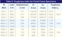
- Crack patterns for PCC, ECC-4, R-ECC and C-ECC are shown in Fig. 8. Single crack formation at the center of the beam and top of the columns were responsible for failure of the PCC specimen. This crack pattern gave information about reinforcement detailing and concrete substitution. Rotation of the beam in the center and at the top of the column was seen in ECC, R-ECC and CECC specimens. The crack pattern of ECC, R-ECC and C-ECC were distinctly different from that of PCC. The first crack started at the midspan of the beam on the tensile face, and multiple cracks developed from the first cracking point and spreaded to the outside of the midspan. The multiple cracks at the outside of the midspan were inclined similar to the shear cracks in the R-ECC beams. As the ultimate load approached, one of the cracks from the midspan started to open up after the development of large damage zone. Horizontal parallel cracks starting from the top of the column at the constant spacing of 2 to 5 cm developed upto the center of the column as shown in Figure 6. The first crack at the top of the column widened and rotation took place from this crack.
- R-ECC specimens having larger resistance to rotation due to reinforcement did not fail due to rotation. Cracks were not seen along the reinforcement even after such large inelastic deformation which indicates good compatibility between reinforcement and ECC. Shear strength of the beam at support became more than ultimate shear strength of ECC material. Shear reinforcement was not provided in the beam. Eventually, beam of RECC failed due to shear from one of the ends as shown in Figure 5. Fractured surface of combination of ECC material with concrete revealed that there is good bond between two materials, without any delamination and spalling.
Conclusion
- Plastic hinges were formed at beam column junction in L and Portal frames. ECC plays significant role in rotation of such plastic hinges in ductile manner. Therefore, energy absorption capacity of plastic hinges in such cases is greatly enhanced. Total collapse of structure can be much delayed or damage can be minimized with the help of such fused zones made with ECC and thus the overall performance of the structure can be improved.
- ECC has compatible deformation and good bond strength with steel reinforcement. Debonding of ECC with steel reinforcement due to shear, spalling, punching was not observed. R-ECC renders maximum improvement in structural performance. Shear resistance of ECC is also quite large. Shear reinforcement can thus be minimized or eliminated, but it requires careful design.
- C-ECC has no problem with flexural strength compatibility. However, it has poor deformation compatibility. It requires further investigation for proper interface behavior.
- In R-ECC, ECC and C-ECC, vertical and inclined multiple cracks with close spacing are observed in beam portion while horizontal cracks with 2 to 3 cm spacing are observed in columns of portal frame specimens. Damage zone is large in column compared to beam. This strong column-weak beam concept can be used for specimen configuration and thus hinge formation in the column can be avoided.
- Tight crack width control is the key property of ECC for durability performance. Ultimate crack width of ECC matrix remains within 150 mm upto quite large load considered to be sound for concrete durability. Thus, ECC can be effectively used in cover with less thickness.
- The additional cost of ECC over normal concrete is mostly because of the use of fibres, higher cement content and use of high performance super– plasticizer. This is the reason why optimization of the composite to minimize the fibre content is so important. Finally, economy of ECC should be based on cost/benefit analysis. The life cycle cost of structure includes not only the initial material cost but also the construction and maintenance cost.
Acknowledgment
The authors would like to thank Reliance Industries Ltd., Grasim Industries Ltd., and Fosroc Chemicals Ltd. for supporting this research work by providing Recron 3s fibers, Kamal brand 53 Grade OPC cement and Conplast Super Plasticizer respectively. Thanks are also due to the funding agency DST, New Delhi for providing a grant of Rs. 25.6 Lakhs, under FIST Project, to Prof. S. C. Patodi for upgrading the testing facilities used in this investigation.References
- Fischer, G. and Li, V. C. "Intrinsic Response Control of Moment-Resisting Frames Utilizing Advanced Composite Materials and Structural Elements," ACI Structural Journal, Title No. 100-S18, March-April 2003.
- Li, V. C. "Large Volume, High-Performance Applications of Fibers in Civil Engineering," ACE-MRL, Department of Civil and Environmental Engineering, University of Michigan, Ann Arbor, Michigan, DOI 10.1002/ app. 2263, 2000.
- Fischer, G. and Li, V. C. "Effect of Matrix Ductility on Deformation Behavior of Steel Reinforced ECC Flexural Members under Reversed Cyclic Loading Conditions," ACI Structural Journal, No. 99-s, pp. 79, 2002.
- Li, V. C. "On Engineered Cementitious Composites (ECC)- A Review of the Material and its Applications," Journal of Advanced Concrete Technology, Vol. 1, No. 3, pp. 215- 230, Nov. 2003. Rathod, J. D., Patodi, S. C., Parikh, B. K. and Patel, K. H. "Study of Recron 3S Fibers Reinforced Cementitious Composites," National Conference on Emerging Technology and Developments in Civil Engineering, Amravati, pp. I-88 to I-95, March 2007.
Published on:
08 January 2009
Published in: NBM&CW June 2008
Share:
We Value Your Comment