Carbonation A Durability Threat for Concrete
Jayobroto Burman Roy, General Manager, ATS Infrastructure Ltd. Noida

Introduction
The term “Carbonation” of concrete means the chemical reaction between carbon dioxide in the air and hydration products of the cement. The process includes:
- Diffusion of CO2 in the gaseous phase into the concrete pores,
- Its dissolution in the aqueous film of these pores,
- The dissolution of solid Ca(OH)2in the water of the pores,
- The diffusion of dissolved Ca(OH)2in pore water and its reaction with the dissolved CO2,
Final result of several steps through which the calcium carbonate is formed may simply be described by the following reaction which is assumed to be irreversible.
Ca2+(aq) + 2(OH¯)(aq) + CO2(aq) CaCO3(s) + H2O (Eq.1.1)

When Ca(OH)2is removed from the paste, hydrated CSH, C3S and C2S will also carbonate.
3CaO·SiO2·3H2O+3CO2 3CaCO3+2SiO2+3H2O (Eq. 1.2)
Factors affecting Concrete Carbonation
The rate of carbonation depends on porosity (for CO2to Diffuse) & moisture content of the concrete (for dissolution of solid Ca(OH)2). The diffusivity of CO2 depends upon the pore system of hardened concrete and the exposure condition. The pore system of concrete depends upon the type and the content of binder, water/binder ratio, and the degree of hydration. Thus, the main factors affecting concrete carbonation are:
- Pore system of Hardened Concrete which in turn depends upon w/c ratio, type of binder, and degree of hydration,
- Relative humidity (for dissolution of Ca(OH)2),
- The concentration of CO2.
Optimal conditions for carbonation occur at a RH of 50% (range 40–90%).- If RH <40%, CO2 cannot dissolve,
- If RH >90%, diffusion of carbon dioxide will be inhibited by the water that has filled the pores and hence CO2 cannot enter the concrete.
- The most dangerous range of relative humidity for carbonation is 40% to 80%, since the carbonation reaction calls for the presence of water, while under higher atmospheric humidity the diffusion of carbon dioxide will be inhibited by the water that has filled the pores.

Carbonation and Concrete Durability
Understanding Corrosion

Corrosion is an electrochemical process involving the flow of charges (electrons and ions). At active sites on the bar, called anodes, iron atoms lose electrons and move into the surrounding concrete as ferrous ions. This process is called a half-cell oxidation reaction, or the anodic reaction, and is represented as: (Figure 1.2).
2Fe’ -> 2Fe2++ 4e- (Eq. 1.3)
2H2O + O2 + 4e-’ -> 4OH- (Eq. 1.4)
2Fe2++ 4OH-’ -> 2Fe(OH)2 (Eq. 3.5)

This initial precipitated hydroxide tends to react further with oxygen to form higher oxides. The increases in volume as the reaction products react further with dissolved oxygen leads to internal stress within the concrete that may be sufficient to cause cracking and swelling of the concrete cover.
Consequence of Carbonation
- Carbonation results in a decrease of the porosity making the carbonated paste stronger. Carbonation is therefore an advantage in non-reinforced concrete.
- However, main consequence of carbonation is the drop in the pH of the pore solution in the concrete from the standard values between 12.5 and 13.5, to a value below 9 in the fully carbonated zones, so that the passive layer that usually covers and protects the reinforcing steel from corrosion becomes unstable.

Once this layer is destroyed rusting of iron bars and subsequent expansion of the concrete takes place and durability of concrete decreases. Hence Carbonation is harmful for reinforced concrete.
Methods to Measure Carbonation
Extent of Carbonation is measured in two ways:
- First way is to measure the concentration of CO2 absorbed by the concrete specimen.
- Second way is to carbonate the specimen in (a) natural or (b) laboratory environment conditions and then break it and spray a pH indicator to know the extent of Carbonation.
Both methods are described in detail on next page.
IR Spectrum Analysis

The carbonation set-up consists of a close loop in which a mixture of air and carbon-dioxide could be introduced at a certain RH. Due to the carbonation reaction, an amount of CO2 molecules will be immobilized reducing the concentration of carbon dioxide in the circulating gas mixture. The CO2 concentration in the gas is measured using an IR absorption device. A pump is used to circulate the gas while also temperature and RH are measured.
Using pH Indicators
In this method, first concrete specimen is kept in an open environment for a number of years or in Carbonation Chamber for a number of months. Generally, conditions of 70% CO2, 50% Relative Humidity, and 20-22ºC is maintained in a carbonation chamber, fig. 1.4(a). Then sample is broken and is sprayed with a pH indicator. Popularly a standard solution of 1% phenolphthalein in 70% ethyl alcohol is used. In the noncarbonated region with pH values above 9.2, the phenolphthalein indicator turns purple-red; and in the carbonated portion with pH less than 9.2, the solution remained colorless. Figure 1.4(a), (b).

Literature Review
Figure 1.6 shows a compilation of carbonation depth by various researchers. It was found that most of the researches were confined to a particular zone of compressive strength. Very less data is found concrete above 60 MPa concrete strength.
Figure 1.5 shows the collection of various carbonation depth verses strength. It is noted that most of the research is done on concrete with strength below 60 MPa. The value and variation of data after this is negligible. Figure 1.6 shows the results of rapid carbonation. It shows slightly higher depth but follows similar trend. Figure 1.7 shows a critical analysis of Figure 1.5. Table 1.1 shows a few sets of distinct data derived from Figure. 1.5

Following conclusions can be arrived:

- Carbonation Depth shows a good variation and possibly a good method to judge durability upto 60 MPa.
- After 60 Mpa Compressive Strength, the values of normal carbonation depth are insignificant and it is difficult to access the durability of concrete.
- Based on the table no 1.1, following bound distribution can be made:
- Normal concrete is distributed over whole bound,
- Concrete with one pozollonic material is lying in middle and lower bound,
- Concrete with mixed pozollonic materials is lying in lowerbound.
- The plot shows that concretes with mixed pozollonic materials (till 30%) are more reliable w.r.t. carbonation depth as compared to normal concrete or concretes with only one pozollonic material.
Numerical Prediction Method

Jiang et. al. presented a good numerical modeling as presented below for normal and high volume flyash:
The model for predicting HVFA concrete carbonation is in good agreement with the test results obtained in an accelerated carbonation apparatus. It can be used to predict the evolution of carbonation depth with time. However, more tests are required to confirm these preliminary observations. From this study, it can also be seen that at a given binder content, the carbonation depth of HVFA concrete is greater than OPC concrete. The increase of curing period can improve the carbonation behavior of HVFA concrete. The carbonation depth of HVFA concrete of appropriate mix proportion can approach that of OPC concrete, and meet the requirements of structural concrete.
Experiments
Carbonation Depth Results Analysis of Carbonation Results
Relationshp between carbonated depth vs. Strength are plotted here.
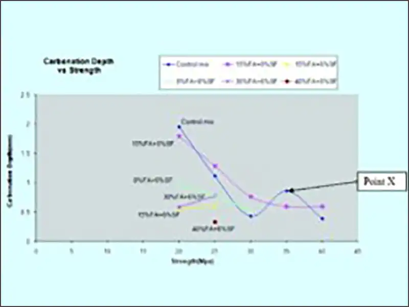
The values of carbonation depth have been plotted against design strength in Figure 1.13. It has been divided into 6 parts. Each part is the line representing for a fixed replacement level of fly ash and silica fume. It is a comprehensive graph and it can be seen very clearly that as strength increases the carbonation depth values are decreasing.

If we assume that carbonation depth are directly related to durability of concrete, i.e. higher the carbonation depth lower will be durability, following conclusion can be given.
- The effect of 15% replacement by Fly Ash is not clear. Carbonation depth has increased for M25, M30, and M40 but decreased for M20 and M35. In Figure 4.8 if we delete point ‘X’ then we may conclude that 15% Flyash replacement increases carbonation depth and will therefore decreases durability. In this experiment samples were water-cured for 28 days only. What would have happened if samples were water-cured for 56 days? Will it result in better durability of concrete with 15% replacement by Flyash?
- 6% replacement by Silica Fume showed significant decrease in Carbonation Depth, hence is more durable.
- 15% Flyash and 6% silica Fume replacement shows further fall in carbonation depth values, hence it is even more durable.
- Due to less available data not much can be said about concrete with 30%FA and 6%SF replacement or 40%FA and 6% FA replacements, but it is clear that concrete made by double replacement of cement generally shows better durability property as compared to single replacement or no replacement.
- Double replacement of 40% fly– ash and 6% silica fume shows least carbonation. However, exact replacement levels which would give maximum durability without going for a higher strength concrete is cannot be predicted.
- The argument that “pozzolana decreases conc. of Ca(OH)2 and CO2 has to react with less Ca(OH)2 and hence carbonated front should move faster inside concrete” seems void. Except for 15% Flyash replacement, all other pozzolana/flyash concretes have shown lower carbonation.
- Variation of the graph is very-very similar to as predicted after Literature Review (see Figure1.5-8)
Conclusion
In this discussion, the mechanism of carbonation along with the adapted experimental methods are presented. Phenolphthalein method of detecting depth of carbonation is found to be the most popular method. A lot of experimental and imperical model to estimate carbonation (Jiang et al.) have been reported in literature.
Carbonation data from various literature have been plotted for comparative study and excellent co-relation where noticed. Indeed Jiang et al. model must have simulated all these results. It was noticed that a lot of data exists under 60 MPa concrete. Very less data exist for concrete above 60 MPa. This is because above 60 MPa, the depth of carbonatin is insignificant.