Biofouling and Corrosion of Specialty Coated Reinforcement
Embedded in Concrete Exposed to Natural Marine Environment
P. Venkatesan, Central Electrochemical Research Institute (CSIR), Karaikudi.
Marine organisms can modify the local environment of the structures, by influencing oxygen concentration cells, changing the pH and also through the production of metabolites, which create a more aggressive electrolyte. Algae are capable of raising the pH to above two units than that of the seawater and lower it to 1.8 when they decompose. The hard fouler such as barnacles are capable of reducing the pH to 1-2 beneath the base of their shell.
Fouling can enhance corrosion by bacterial action of both aerobic and anaerobic nature. The sulphur oxidizing bacteria, Thio bacillus sp. oxidise inorganic sulphate and produce sulfuric acid, which is corrosive to steel and concrete.
The corrosion of the reinforcement embedded in the concrete is the main cause of damage and early failure of reinforced concrete structures especially those located in aggressive marine and industrial environment. The reinforcement in all the structures provides a constructional security. Steel embedded in good quality concrete is protected by the high alkalinity of pore water, which in the presence of oxygen, passivates the steel. The loss of alkalinity due to carbonation of the concrete and the penetration of chloride ions to steel can destroy the passive film. It is believed that reinforced concrete structures are durable and maintenance-free for the whole of its design life, approximately more than 60 years. However, the corrosion of reinforcing steel in concrete exposed to aggressive environment affects the life of the concrete and thus has rapidly become a serious problem throughout the world. Parking structures, bridges, buildings, and other reinforced concrete structures exposed to marine and industrial environments are being severely damaged due to corrosion of reinforcing steel within periods as short as 10 to 20 years.
In marine environment, reinforcing steel corrosion is the natural result of the penetration of chloride up to reinforcement position.
As corrosion products have volume two to four times higher than that of iron, stress is created within the concrete causing irreversible damage to the reinforced concrete structure:
(i) cracking of concrete
(ii) reduction in load carrying capacity and
(iii) failure of the structure.
Understanding of the corrosion mechanism as well as the rates of deterioration demands the long-term studies. Among the nondestructive methods: electrochemical measurements (Open circuit potential measurements, corrosion rate measurement) are reliable. Duffo et al. characterised the corrosion products at the steel/concrete interface for 65 years old specimens exposed to atmospheric environment. Chitty et al. studied archaeological analogues corrosion systems taken from different buildings aged from 80 to 1700 years old. A complete characterization based on macro and microscopic methods has been performed.
The main constituents of rust formed on atmospheric corroded steel are iron oxyhydroxide, ferric oxides and magnetite.
The corrosion process of a steel reinforcement in concrete is different from those of a steel coupon exposed to atmosphere, and more similar to steel immersed in alkaline solution.
Jain et al. in addressing rust composition of steel reinforced concrete, inform that the final corrosion products are Fe3O4 and b–Fe OOH. The presence b–Fe OOH in rust was due to the presence of chloride ions in concrete.
Poupard et al. carried out detailed investigation of chloride-induced corrosion on 40 years old reinforced concrete beam exposed in natural marine environment. Visual observations, electrochemical measurements, carbonation depth, total chloride content were located using half-cell potential measurements. The real corrosion state of steel reinforcements was observed by applying destructive methods. The corrosion products and the steel/concrete interface characterized by optical, XRD, SEM, EDS and ì- Raman techniques.
Poupard et al. based on diagnosis results of the corrosion damage of a prestressed concrete beam after 40 years of exposure in marine environment suggested that Chloride ions are only responsible for corrosion attack and he distinguished two types of corrosion zones.
Organic coatings are a cost-effective way to protect metals. However, at defects or sites of damage in the coating, a local corrosion cell develops leading to coating breakdown. Alkali generated at the cathode tends to inhibit anodic attack in these areas, but reduces the adhesion between coating and metal to zero, results in debonding around the defect or blisters near the defect. The controlling factors in coating delamination have been extensively studied. These experiments show the same reversal of polarity seen previously.
On the basis of the data, Asthana concluded that the IPN-coated reinforcing bars have acceptable bond strength with concrete, and have better corrosion resistance than other commercially available treatment used for similar applications. The economics of the treatment is quite attractive since treatment costs about 15 to 20% of the cost of steel. Hence it may be said that IPN-coated reinforcing steel bars fulfill the minimum requirements laid down in various standard specifications. Asthana K.K. concludes from the studies that the IPN coated steel reinforcement bars would have a more extended life in comparison to uncoated reinforcement.
The pH may get lowered if the concrete contains chlorides, sulphates, and other deleterious chemicals. These chemicals diffuse through the concrete and lower the pH value of the water in the pores of concrete. As a result, protective oxide film is pierced by these chemicals, which will then attack the reinforcement.
Alblasand London reviewed the literature concerning the effect of chloride contamination on the corrosion of coated steel surfaces. Appleman, Helvig, Weldon and Flores showed various correlations between level of chloride and premature coating failures. These investigators applied the contaminant (chloride) in known quantities to the steel surface and applied the coating shortly thereafter. Niel and Whitehurst used chloride contamination that remained in the micropits after sand blasting of steel surface for studying FBE coating performance. They found that in the presence of a pitted surface, chloride contamination could cause serious loss of performance in FBE coatings in hot cathodic disbonding and hot water tests. For underground coatings and other immersion coatings in critical applications, a maximum chloride level of 2 ppm was suggested.
It is generally assumed for steels without surface coatings that chloride-induced corrosion results from the breakdown of the passive film. In the presence of a passive film, it is believed that the corrosion process results from the electrostatic attraction between the positively charged metal surface and the negatively charged chloride ions. It is believed that chloride ions react at areas where the passive film is discontinuous, damaged, or at heterogeneous sites on the steel surface. After initiation, the chloride ions are used as a catalyst for the liberation of iron ions, resulting in further corrosion.
The corrosion performance of steel reinforcement embedded in cementitious materials exposed to chlorides is a function of both the concrete and steel characteristics.
In this paper the corrosion behavior of mild steel reinforced plain rods and with three different types of coatings exposed to natural marine environment over a period of four years is presented.
Corrosion rate of reinforcements embedded in concrete and immersed in seafloor for about four years was measured by the following electrochemical techniques: a) Linear Polarisation Resistance (LPR), b) a.c. Impedance and c) Electrochemical Noise (ECN).
For gravimetric study, the reinforced concrete specimens were broken open. The rust products were removed by immersing the reinforcement in pickling acid. The weight of the reinforcement steel rods was taken then loss in weight was calculated. The corrosion rate (Eq. 1) was estimated using the relationship,
Corrosion rate (mmpy) = 87.6 W . . .(1)
D A T
Where W is the weight loss in milligrams, D is the density of the material in gm/cm3, A is the surface area of the reinforcement in cm2, and T is the exposure time in hours.
A saturated calomel electrode having a wetted cotton tip was placed over the concrete surface. Open circuit potential between the reinforcement rod and the reference electrode was measured periodically using a multimeter.
The water-soluble chloride was estimated by volumetric method by preparing cement extract. The test solution was neutralized with diluted sulphuric acid (H2SO4) then titrated against standard silver nitrate (AgNO3) using potassium chromate as indicator.
wave action of the sea. Due to this, the specimens were subjected to alternate wet and dry conditions.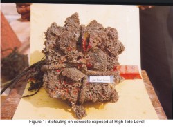 The deterioration of concrete cubes exposed to natural marine environment over a period of four years is presented. The results based on visual inspection is presented and discussed.
Biofouling present in the specimens immersed at seafloor promotes the microbial induced corrosion in the specimens. Anerobic conditions increases the corrosion rate. The biogeneric bacteria produces the sulphide which promotes the corrosion in anaerobic condition.
Biological corrosion is the deterioration of a metal by corrosion process that occurs directly or indirectly as a result of the activity of living organisms. These organisms include microforms such as bacteria and macro types such as algae and barnacles.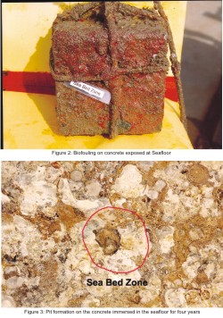 Anaerobic bacteria grow most favorably in environments containing little or no oxygen. Anaerobic bacteria that influence the corrosion behavior of buried steel structures are the Sulfate-reducing types. These reduce sulfate to sulfide according to the following schematic equation:
SO4 2- + 4H2 ---> S2- + 4H2O
The source of hydrogen in the above equation can be that evolved during the corrosion reaction or other organic products present in the soil.
Sulfate-reducing bacteria are most prevalent under anaerobic conditions. The presence of sulfide ion markedly influences both the cathodic and anaodic reactions occurring on iron surfaces. Sulfide tends to retard cathodic reactions, particularly hydrogen evolution, and accelerates anodic dissolution. The acceleration of dissolution causes increased corrosion. The corrosion product in the presence of sulfate-reducing bacteria is iron sulfide, which precipitates when ferrous and sulfide ions are in contact.
 Iron bacteria are a group of microorganisms that assimilate ferrous iron from solution and precipitate it as ferrous or ferric hydroxide. The growth of iron bacteria frequently results in tubercles on steel surfaces and tends to produce corrosion attack. Concrete is less satisfactory in the presence of sulfur-oxidizing bacteria because it is also rapidly attacked by the sulfuric acid environment.
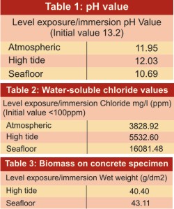
 The water-soluble chloride content of the extract prepared from the concrete specimens exposed at different levels is presented in the table 2. As seen from the Table 4, the chloride content was maximum for seafloor level exposure and minimum for atmospheric level exposure.
The Table 3 details regarding biomass on the reinforced concrete specimens after six months immersion in sea at various depths.
The following bacteria enumerated after three months exposure to natural marine environment) heterophic bacteria (HB), iron bacteria (FB), manganese depositing bacteria (MB), acid producing bacteria (APB) and sulphate reducing Bacteria (SRB).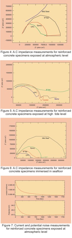 The potential time behavior of reinforcement coated with specialty coating, embedded in concrete and immersed in seafloor level in natural marine environment are presented and discussed
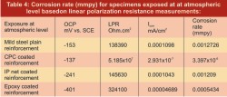
The Table 4 shows the corrosion rate at atmospheric level based on linear polarization resistance measurements for mild steel reinforcements after completion of four years of immersion in seafloor.
The Table 5 shows the corrosion rate at high tide level based on linear polarization resistance measurements for mild steel reinforcements, after completion of four years of immersion in seafloor.
The Table 6 shows the corrosion rate based on linear polarization resistance measurements for mild steel reinforcements after completion of four years of immersion in seafloor.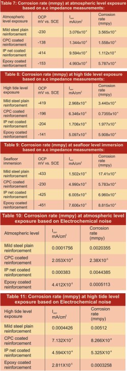 The a.c impedance measurements of reinforcement coated with specialty coating, embedded in concrete and exposed at atmospheric level, Fig. 4, in natural marine environment are presented.
The Table 7 shows the corrosion rate based on a.c impedance method for mild steel reinforcements after completion of four years atmospheric level exposure.
The Table 8 shows the corrosion rate based on a.c impedance method for mild steel reinforcements after completion of four years high tide level exposure.
The Table 9 shows the corrosion rate based on a.c impedance method for mild steel reinforcements after completion of four years immersion in seafloor.
Table 10 shows the corrosion rate based on electrochemical noise method for mild steel reinforcements after completion of four years immersion in atmospheric level
Table 11 shows the corrosion rate based on electrochemical noise method for mild steel reinforcements after completion of four years immersion in high tide level.
The Table 12 shows the corrosion rate based on electrochemical noise method for mild steel reinforcements after completion of four years immersion in seafloor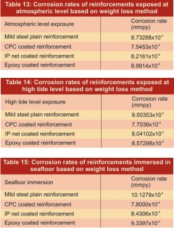 The concrete specimens with mild steel plain reinforcement were exposed at atmospheric level, high tide Level and seafloor immersion in natural marine environment at offshore platform for four years. The corrosion rate of reinforcement based on weight loss (Gravimetric) method are presented and discussed. The weight loss measurements were performed after removing the specialty coatings by mechanical means.
The Table 13 shows the corrosion rate based on weight loss method for mild steel reinforcements after completion of four years at atmospheric level.
The Table 14 shows the corrosion rate for mild steel reinforcements after completion of four years at high tide level based on weight loss method.
The Table 15 shows the corrosion rate based on weight loss method for mild steel reinforcements after completion of four years at seafloor level. The corrosion rate was highest at seafloor level.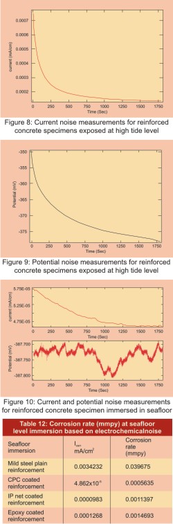 The specialty coated reinforcements broken open from concrete specimens were visually examined; the observations are presented and discussed. The reinforcements are in the following order: CPC, control, epoxy and IP net-coated reinforcements.
Visual examination of the seafloor immersed reinforcement revealed that the corrosion prominently present in the control bar. Corrosion patch measuring 19mm was observed in control reinforcement.
Pitting corrosion was observed in the epoxy coated reinforcement. Pitting corrosion patch measuring 7mm was observed.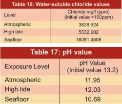 The pH values of the extract prepared from the concrete specimens exposed at different levels are presented in Table 17. The pH value got reduced from initial value of 13.2 to approximately 11 for all the three levels.
The deterioration due to biofouling reduces the effective cover of the reinforced concrete
The corrosion rate of reinforcement embedded in the concrete is higher at seafloor.
The electrochemical noise method is well suitable for measuring the corrosion rate of reinforced concrete structures. The corrosion rate obtained by using the electrochemical noise measurement is well comparable with the other electrochemical methods as well as Gravimetric method.
The influence of biofouling on concrete was studied by exposing reinforced concrete specimens in natural marine environment. The facilities at Offshore Platform and Marine Electrochemical Centre (OPMEC), Tuticorin were utilized for the study. The OPMEC unit is located at about two Kilometers away from seashore. The reinforced concrete specimens were exposed at atmospheric level, high tide level, and immersed in seafloor for four years. The Marine fouling on concrete including macro fouling and micro fouling were studied. The concrete specimens immersed in seafloor higher biomass of 40.4 g/dm2 (wet weight) while surface sample shows lower biomass of 40.4 g/dm2. Barnacles, Molluscs, ascidians and bryozoans were the major fouling community at, all the three level studies. Corrosion rate was high for reinforced concrete immersed in seafloor.
Corrosion of reinforcement is a major problem for the reinforced concrete structures constructed in marine as well as in industrial areas. In this research paper corrosion of mild steel plain bar reinforced concrete immersed in seafloor for four years is presented. The reinforcements are coated with three different types of corrosion protection by specialty coatings, namely cement polymer composite, interpenetrating polymer network and epoxy coating. The corrosion behavior is monitored using Open Circuit Potential (OCP) measurements periodically. After completion of four years the reinforced concrete specimens were subjected to the following measurements:- linear polarisation resistance (LPR), a.c. impedance, electrochemical noise (ECN) and weight loss technique. Based on the above measurements using Stern-Geary equation the corrosion rate was calculated. The pH measurement, chloride analyses were also carried out. The results are presented and discussed.
Introduction
Marine fouling is the visible sign of infestation by various sedentary organisms practically on all-engineering materials used for marine and offshore services. Materials submerged in the ocean follow a sequence of physical, chemical and biological changes at their surfaces, following a surface conditioning by organic matter. Microorganisms, apart from affecting corrosion by them selves, aid in the colonization of spores of algae and the larval form of macro fouling organisms (Secheer and Gunderson, 1873; Corp, 1976). The composition, extent and rate of development of a macro-fouling community at any site is determined by the interaction of many variables, notably geographic location, nutrient availability, light levels, water depth and its biota. The settlement of some species, particularly barnacle is not always random but may be encouraged by the presence of other individuals of the same species.Marine organisms can modify the local environment of the structures, by influencing oxygen concentration cells, changing the pH and also through the production of metabolites, which create a more aggressive electrolyte. Algae are capable of raising the pH to above two units than that of the seawater and lower it to 1.8 when they decompose. The hard fouler such as barnacles are capable of reducing the pH to 1-2 beneath the base of their shell.
Fouling can enhance corrosion by bacterial action of both aerobic and anaerobic nature. The sulphur oxidizing bacteria, Thio bacillus sp. oxidise inorganic sulphate and produce sulfuric acid, which is corrosive to steel and concrete.
The corrosion of the reinforcement embedded in the concrete is the main cause of damage and early failure of reinforced concrete structures especially those located in aggressive marine and industrial environment. The reinforcement in all the structures provides a constructional security. Steel embedded in good quality concrete is protected by the high alkalinity of pore water, which in the presence of oxygen, passivates the steel. The loss of alkalinity due to carbonation of the concrete and the penetration of chloride ions to steel can destroy the passive film. It is believed that reinforced concrete structures are durable and maintenance-free for the whole of its design life, approximately more than 60 years. However, the corrosion of reinforcing steel in concrete exposed to aggressive environment affects the life of the concrete and thus has rapidly become a serious problem throughout the world. Parking structures, bridges, buildings, and other reinforced concrete structures exposed to marine and industrial environments are being severely damaged due to corrosion of reinforcing steel within periods as short as 10 to 20 years.
In marine environment, reinforcing steel corrosion is the natural result of the penetration of chloride up to reinforcement position.
As corrosion products have volume two to four times higher than that of iron, stress is created within the concrete causing irreversible damage to the reinforced concrete structure:
(i) cracking of concrete
(ii) reduction in load carrying capacity and
(iii) failure of the structure.
Understanding of the corrosion mechanism as well as the rates of deterioration demands the long-term studies. Among the nondestructive methods: electrochemical measurements (Open circuit potential measurements, corrosion rate measurement) are reliable. Duffo et al. characterised the corrosion products at the steel/concrete interface for 65 years old specimens exposed to atmospheric environment. Chitty et al. studied archaeological analogues corrosion systems taken from different buildings aged from 80 to 1700 years old. A complete characterization based on macro and microscopic methods has been performed.
The main constituents of rust formed on atmospheric corroded steel are iron oxyhydroxide, ferric oxides and magnetite.
The corrosion process of a steel reinforcement in concrete is different from those of a steel coupon exposed to atmosphere, and more similar to steel immersed in alkaline solution.
Jain et al. in addressing rust composition of steel reinforced concrete, inform that the final corrosion products are Fe3O4 and b–Fe OOH. The presence b–Fe OOH in rust was due to the presence of chloride ions in concrete.
Poupard et al. carried out detailed investigation of chloride-induced corrosion on 40 years old reinforced concrete beam exposed in natural marine environment. Visual observations, electrochemical measurements, carbonation depth, total chloride content were located using half-cell potential measurements. The real corrosion state of steel reinforcements was observed by applying destructive methods. The corrosion products and the steel/concrete interface characterized by optical, XRD, SEM, EDS and ì- Raman techniques.
Poupard et al. based on diagnosis results of the corrosion damage of a prestressed concrete beam after 40 years of exposure in marine environment suggested that Chloride ions are only responsible for corrosion attack and he distinguished two types of corrosion zones.
Organic coatings are a cost-effective way to protect metals. However, at defects or sites of damage in the coating, a local corrosion cell develops leading to coating breakdown. Alkali generated at the cathode tends to inhibit anodic attack in these areas, but reduces the adhesion between coating and metal to zero, results in debonding around the defect or blisters near the defect. The controlling factors in coating delamination have been extensively studied. These experiments show the same reversal of polarity seen previously.
On the basis of the data, Asthana concluded that the IPN-coated reinforcing bars have acceptable bond strength with concrete, and have better corrosion resistance than other commercially available treatment used for similar applications. The economics of the treatment is quite attractive since treatment costs about 15 to 20% of the cost of steel. Hence it may be said that IPN-coated reinforcing steel bars fulfill the minimum requirements laid down in various standard specifications. Asthana K.K. concludes from the studies that the IPN coated steel reinforcement bars would have a more extended life in comparison to uncoated reinforcement.
The pH may get lowered if the concrete contains chlorides, sulphates, and other deleterious chemicals. These chemicals diffuse through the concrete and lower the pH value of the water in the pores of concrete. As a result, protective oxide film is pierced by these chemicals, which will then attack the reinforcement.
Alblasand London reviewed the literature concerning the effect of chloride contamination on the corrosion of coated steel surfaces. Appleman, Helvig, Weldon and Flores showed various correlations between level of chloride and premature coating failures. These investigators applied the contaminant (chloride) in known quantities to the steel surface and applied the coating shortly thereafter. Niel and Whitehurst used chloride contamination that remained in the micropits after sand blasting of steel surface for studying FBE coating performance. They found that in the presence of a pitted surface, chloride contamination could cause serious loss of performance in FBE coatings in hot cathodic disbonding and hot water tests. For underground coatings and other immersion coatings in critical applications, a maximum chloride level of 2 ppm was suggested.
It is generally assumed for steels without surface coatings that chloride-induced corrosion results from the breakdown of the passive film. In the presence of a passive film, it is believed that the corrosion process results from the electrostatic attraction between the positively charged metal surface and the negatively charged chloride ions. It is believed that chloride ions react at areas where the passive film is discontinuous, damaged, or at heterogeneous sites on the steel surface. After initiation, the chloride ions are used as a catalyst for the liberation of iron ions, resulting in further corrosion.
The corrosion performance of steel reinforcement embedded in cementitious materials exposed to chlorides is a function of both the concrete and steel characteristics.
In this paper the corrosion behavior of mild steel reinforced plain rods and with three different types of coatings exposed to natural marine environment over a period of four years is presented.
Materials and Methods
Mild steel plain bar of diameter 16 mm and length 200 mm was used as reinforcement for the concrete. The initial weight of the mild steel rebar specimens was recorded for gravimetric studies. Electrical wires were soldered to the mild steel rods for electrochemical studies. The reinforcement concrete specimens of dimensions 150 X 150 X 300 mm reinforced with mild steel plain bars were cast. The concrete mix proportion was 1: 1.2: 2.4. Ordinary Portland cement with river sand as fine aggregate and 20 mm stones as coarse aggregate were used. The water cement ratio used was 0.45. The concrete cover provided to the reinforcement was 50 mm. Three coatings of cement polymer composite coating (CPC), Interpenetrating polymer network coating (IPN) and epoxy coating (EC) were applied for a an average thickness of 150±25mm for various reinforcements. Identical cubes without reinforcing rods were cast and tested in the universal compression-testing machine for obtaining compressive strength. The compressive strength is 40 Mpa.Corrosion rate of reinforcements embedded in concrete and immersed in seafloor for about four years was measured by the following electrochemical techniques: a) Linear Polarisation Resistance (LPR), b) a.c. Impedance and c) Electrochemical Noise (ECN).
For gravimetric study, the reinforced concrete specimens were broken open. The rust products were removed by immersing the reinforcement in pickling acid. The weight of the reinforcement steel rods was taken then loss in weight was calculated. The corrosion rate (Eq. 1) was estimated using the relationship,
Corrosion rate (mmpy) = 87.6 W . . .(1)
D A T
Where W is the weight loss in milligrams, D is the density of the material in gm/cm3, A is the surface area of the reinforcement in cm2, and T is the exposure time in hours.
A saturated calomel electrode having a wetted cotton tip was placed over the concrete surface. Open circuit potential between the reinforcement rod and the reference electrode was measured periodically using a multimeter.
The water-soluble chloride was estimated by volumetric method by preparing cement extract. The test solution was neutralized with diluted sulphuric acid (H2SO4) then titrated against standard silver nitrate (AgNO3) using potassium chromate as indicator.
Exposure details
For the study of the reinforced concrete specimens in natural marine environment the unique facility available at the Offshore Platform and Marine Electrochemistry Centre (OPMEC), an unit of Central Electrochemical Research Institute (CSIR) situated at a distance of two km from seashore located at Tuticorin, India was made use of. The reinforced concrete specimens were tied using polypropylene wire and suspended from the platform of OPMEC unit. The specimens were positioned at three different levels identified as atmospheric, high tide and seafloor.Atmospheric Level (AL)
The reinforcement concrete specimens were positioned at the platform and exposed to typical natural marine atmosphere.High tide Level (HL)
High tide level refers to the depth at which the reinforcement concrete specimen was subjected to severewave action of the sea. Due to this, the specimens were subjected to alternate wet and dry conditions.
Seafloor Level (SFL)
Seafloor level corresponds to the level where the submerged reinforcement concrete specimens were placed on the seafloor under the sea. This refers to a depth of approximately nine meter from the offshore platform.Results and Discussions
Visual Inspection
The concrete specimens were taken away from exposure site after completion of four years. Then the biofouling scraped without affecting the concrete surface. The deterioration on the concrete surface was visually examined; the observations are presented and discussed.Atmospheric level exposure
The significant deterioration of concrete is nil, no pit formation on the concrete for specimens exposed at atmospheric level for four years.High tide level exposure
Concrete specimens exposure at High tide level shown Figure 1, pit measuring 7.04 mm in depth and 17.06 mm in diameter on concrete specimens exposed at high tide level for four years. The effective concrete cover is reduced from 50 mm to 43 mm, thus 14% reduction in the concrete cover provided to the reinforcement. The hardened cement paste was missing giving way to pit formation. At high tide level immersed reinforced concrete specimens deterioration is caused by aqueous organisms of animal and plant life, including barnacles, mussels, algae, and others. The accumulation of barnacles, mussels, algae, and other organisms causes corrosion. The reinforced concrete specimens exposed at high tide level is subjected to alternate wet and dry condition. When sea is calm or at low tide level the specimens are in dry exposure condition. In dry exposure condition sunlight falls on the specimens resulting in the death of the aqueous organisms. These phenomena reduce the corrosion caused by aqueous organisms.Seafloor immersion
Concrete specimens immersed in seafloor level as shown in figure 2 & 3, pit measuring 9.72 mm depth and 19.36 mm diameter for concrete specimens immersed in seafloor for four years. The effective concrete cover is reduced from 50 mm to 40 mm, thus 20% reduction in the concrete cover provided to the reinforcement. The hardened cement paste was missing giving way to pit formation.Biofouling present in the specimens immersed at seafloor promotes the microbial induced corrosion in the specimens. Anerobic conditions increases the corrosion rate. The biogeneric bacteria produces the sulphide which promotes the corrosion in anaerobic condition.
Biological corrosion is the deterioration of a metal by corrosion process that occurs directly or indirectly as a result of the activity of living organisms. These organisms include microforms such as bacteria and macro types such as algae and barnacles.
Microorganisms
SO4 2- + 4H2 ---> S2- + 4H2O
The source of hydrogen in the above equation can be that evolved during the corrosion reaction or other organic products present in the soil.
Sulfate-reducing bacteria are most prevalent under anaerobic conditions. The presence of sulfide ion markedly influences both the cathodic and anaodic reactions occurring on iron surfaces. Sulfide tends to retard cathodic reactions, particularly hydrogen evolution, and accelerates anodic dissolution. The acceleration of dissolution causes increased corrosion. The corrosion product in the presence of sulfate-reducing bacteria is iron sulfide, which precipitates when ferrous and sulfide ions are in contact.
pH Value
The pH values of the extract prepared from the concrete specimens exposed at different levels are presented in Table 1. The pH value got reduced from initial value of 13.2 to approximately 11 for all the three levels.Chloride Content
Biofouling
In this section biofouling on the 100 mm concrete cubes immersed for six months at high tide, low tide levels and immersed at seafloor is presented.The Table 3 details regarding biomass on the reinforced concrete specimens after six months immersion in sea at various depths.
The following bacteria enumerated after three months exposure to natural marine environment) heterophic bacteria (HB), iron bacteria (FB), manganese depositing bacteria (MB), acid producing bacteria (APB) and sulphate reducing Bacteria (SRB).
Potential-Time Behavior Of Reinforced Concrete Specimens Exposed At Atmospheric level In Natural Marine Environment
The potential time behavior of reinforcement with specialty coating, embedded in concrete and exposed to atmospheric level in natural marine environment are presented and discussed.Mild steel plain reinforcement:
On the day of exposure at atmospheric level in natural marine environment the mils steel plain reinforcement showed the OCP values of –129 mV vs. SCE. The mild steel reinforcement was in active condition after completion of 157 days of exposure at atmospheric level as per ASTM C876 since the OCP measurement –275 mV vs. SCE was above –275 mV vs.SCE.Cement Polymer Composite Coated Reinforcement:
On the day of immersion at seafloor in natural marine environment the mild steel plain reinforcement showed the OCP values of–128 mV vs. SCE. The OCP values never crossed–275 mV vs. SCE indicating that the reinforcement was in passive condition.Interpenetrating Polymer Network Coated Reinforcement:
On the day of immersion at seafloor in natural marine environment the Interpenetrating Polymer Network Coated reinforcement showed the OCP measurement as–112 mV vs. SCE. The mild steel reinforcement was in active condition after completion of nearly four years of exposure at atmospheric level as per ASTM C876 since the OCP measurement–414 mV vs. SCE was above–275 mV vs. SCE.Epoxy Coated Reinforcement:
On the day of immersion at seafloor in natural marine environment the Epoxy Coated reinforcement showed the OCP measurement as –214 mV vs. SCE. The mild steel reinforcement was in active condition after completion of 722 days exposure at atmospheric level as per ASTM C876 since the OCP measurement –277 mV vs. SCE was above –275 mV vs. SCE.Potential-Time Behavior Of Reinforced Concrete Specimens Exposed At High Tide Level In Natural Marine Environment
The potential time behavior of reinforcement coated with specialty coating, embedded in concrete and exposed to high tide level in natural marine environment are presented and discussed.Mild steel plain reinforcement:
On the day of exposure at high tide level in natural marine environment the mild steel plain reinforcement showed the OCP values of –110 mV vs. SCE. The OCP measurement after completion of 44 days of exposure at high tide level was –373 mV vs. SCE and was above –275 mV vs. SCE as per ASTM C876, the mild steel reinforcement was in active condition.Cement Polymer Composite Coated Reinforcement:
On the day of immersion at seafloor in natural marine environment the Cement Polymer Composite Coated reinforcement showed the OCP measurement as –98mV vs. SCE. The mild steel reinforcement was in active condition after completion of 44 days of high tide level exposure as per ASTM C876 since the OCP measurement –634 mV vs. SCE was above –275 mV vs. SCE.Interpenetrating Polymer Network Coated Reinforcement:
On the day of immersion at high tide level in natural marine environment the Interpenetrating Polymer Network Coated reinforcement showed the OCP measurement as–132 mV vs. SCE. The mild steel reinforcement was in active condition after completion of 44 days of high tide level exposure as per ASTM C876 since the OCP measurement –357 mV vs. SCE was above –275 mV vs. SCE.Epoxy Coated Reinforcement:
On the day of immersion at high tide level in natural marine environment the epoxy coated reinforcement showed the OCP measurement as –210 mV vs. SCE. The mild steel reinforcement was in active condition after completion of 44 days of seafloor immersion as per ASTM C876 since the OCP measurement –459 mV vs. SCE was above –275 mV vs. SCE.Potential-Time Behavior Of Reinforced Concrete Specimens Immersed At Seafloor Level In Natural Marine Environment
Mild steel plain reinforcement:
On the day of immersion at seafloor in natural marine environment the mils steel plain reinforcement showed the OCP values of –118 mV vs. SCE. The mild steel reinforcement was in active condition after completion of 121 days of seafloor immersion as per ASTM C876 since the OCP measurement –373 mV vs. SCE was above –275 mV vs. SCE.Cement Polymer Composite Coated Reinforcement:
On the day of immersion at seafloor in natural marine environment the Cement Polymer Composite Coated reinforcement showed the OCP measurement as –117 mV vs. SCE. The mild steel reinforcement was in active condition after completion of 157 days of seafloor immersion as per ASTM C876 since the OCP measurement –634 mV vs. SCE was above –275 mV vs. SCE.Interpenetrating Polymer Network Coated Reinforcement:
On the day of immersion at seafloor in natural marine environment the Interpenetrating Polymer Network Coated reinforcement showed the OCP measurement as –140 mV vs. SCE. The mild steel reinforcement was in active condition after completion of 157 days of seafloor immersion as per ASTM C876 since the OCP measurement –528 mV vs. SCE was above –275 mV vs. SCE.Epoxy Coated Reinforcement:
On the day of immersion at seafloor in natural marine environment the Epoxy Coated reinforcement showed the OCP measurement as –148 mV vs. SCE. The mild steel reinforcement was in active condition after completion of 121 days of seafloor immersion as per ASTM C876 since the OCP measurement –293 mV vs. SCE was above –275 mV vs. SCE.Linear polarization measurements:
The concrete specimens with mild steel plain reinforcement were exposed at atmospheric level, high tide Level and seafloor immersion in natural marine environment at offshore platform for four years. The Linear polarization measurements of reinforcement with respect to corrosion are presented and discussed.Linear polarization measurement for specimens exposed at atmospheric level
The linear polarization measurements of reinforcement coated with specialty coating, embedded in concrete and exposed at atmospheric level in natural marine environment are presented and discussed.The Table 4 shows the corrosion rate at atmospheric level based on linear polarization resistance measurements for mild steel reinforcements after completion of four years of immersion in seafloor.
Linear polarization measurements for specimens exposed at high tide level
The linear polarization measurements of reinforcement coated with specialty coating, embedded in concrete and exposed at high tide level in natural marine environment are presented and discussed.The Table 5 shows the corrosion rate at high tide level based on linear polarization resistance measurements for mild steel reinforcements, after completion of four years of immersion in seafloor.
Linear polarization measurements for specimens immersed in seafloor
The linear polarization measurements of reinforcement coated with specialty coating, embedded in concrete and immersed in seafloor in natural marine environment are presented.The Table 6 shows the corrosion rate based on linear polarization resistance measurements for mild steel reinforcements after completion of four years of immersion in seafloor.
Corrosion rate based on a.c impedance measurements:
The concrete specimens with mild steel plain reinforcement were exposed at atmospheric level, high tide Level and immersion in seafloor in natural marine environment at offshore platform for four years. The a.c impedance measurements of reinforcement with respect to corrosion are presented.A.C impedance measur- ements for specimens exposed at atmospheric level
The Table 7 shows the corrosion rate based on a.c impedance method for mild steel reinforcements after completion of four years atmospheric level exposure.
A.C impedance measur- ements for specimens exposed at high tide level
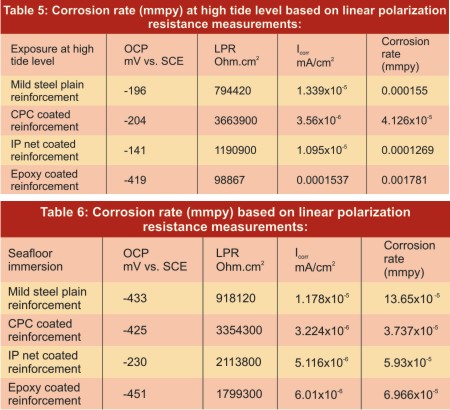
The a.c impedance measurements of reinforcement coated with specialty coating, embedded in concrete and exposed at high tide level, Figure 5, in natural marine environment are presented and discussed.The Table 8 shows the corrosion rate based on a.c impedance method for mild steel reinforcements after completion of four years high tide level exposure.
A.C impedance measurements for specimens immersed in seafloor
The a.c impedance measurements of reinforcement coated with specialty coating, embedded in concrete and immersed in seafloor, Figure 6, in natural marine environment are presented.The Table 9 shows the corrosion rate based on a.c impedance method for mild steel reinforcements after completion of four years immersion in seafloor.
Corrosion rate based on electrochemical noise measurements:
environment at offshore platform for four years. The electrochemical noise measurements of The concrete specimens with mild steel plain reinforcement were exposed at atmospheric level, high tide Level and seafloor immersion in natural marine reinforcement with respect to corrosion are presented.Electrochemical noise measurements for specimens exposed at atmospheric level
The electrochemical noise measurements of reinforcement coated with specialty coating, embedded in concrete and exposed at atmospheric level, Figure 7, in natural marine environment are presented and discussed.Table 10 shows the corrosion rate based on electrochemical noise method for mild steel reinforcements after completion of four years immersion in atmospheric level
Electrochemical noise measurements for specimens exposed at high tide level
The electrochemical noise measurements of reinforcement coated with specialty coating, embedded in concrete and exposed at high tide level, Figure 8 &9, in natural marine environment are presented and discussed.Table 11 shows the corrosion rate based on electrochemical noise method for mild steel reinforcements after completion of four years immersion in high tide level.
Electrochemical noise measurements for specimens immersed in seafloor
The electrochemical noise measurements of reinforcement coated with specialty coating, embedded in concrete and immersed in seafloor, Figure 10, in natural marine environment are presented and discussed.The Table 12 shows the corrosion rate based on electrochemical noise method for mild steel reinforcements after completion of four years immersion in seafloor
Weight loss (Gravimetric) Method:
Weight loss (Gravimetric) measur- ements for specimens exposed at atmospheric level
The weight loss measurements of reinforcement coated with specialty coating, embedded in concrete and exposed at atmospheric level in natural marine environment are presented and discussed.The Table 13 shows the corrosion rate based on weight loss method for mild steel reinforcements after completion of four years at atmospheric level.
Weight loss (Gravimetric) measurements for specimens exposed at high tide level
The weight loss measurements of reinforcement coated with specialty coating, embedded in concrete and exposed at high tide level in natural marine environment are presented.The Table 14 shows the corrosion rate for mild steel reinforcements after completion of four years at high tide level based on weight loss method.
Weight loss (Gravimetric) measurements for specimens immersed in seafloor
The weight loss measurements of reinforcement coated with specialty coating, embedded in concrete and immersed in seafloor in natural marine environment are presented.The Table 15 shows the corrosion rate based on weight loss method for mild steel reinforcements after completion of four years at seafloor level. The corrosion rate was highest at seafloor level.
Visual Inspection
Atmospheric level exposure
The reinforcements are in the order: CPC, control, epoxy and IP net based on open circuit potential measurements.High tide level exposure
The reinforcements are in the order: CPC, control, epoxy and IP net based on open circuit potential measurements.Seafloor immersion
The reinforcements are in the order: CPC, control, epoxy and IP net based on open circuit potential measurements.Visual examination of the seafloor immersed reinforcement revealed that the corrosion prominently present in the control bar. Corrosion patch measuring 19mm was observed in control reinforcement.
Adhesion/bonding between coating and the concrete was good in Cement Polymer Coated reinforcement.
Adhesion/bonding between coating and the concrete was very poor in I.P net-coated reinforcements. Peeling off of coating was observed in the reinforcement coated with I.P net.Pitting corrosion was observed in the epoxy coated reinforcement. Pitting corrosion patch measuring 7mm was observed.
Chloride Content
The water-soluble chloride content of the extract prepared from the concrete specimens exposed at different levels is presented in the table 4. As seen from the Table 16, the chloride content was maximum for seafloor level exposure and minimum for atmospheric level exposure.pH Value
Conclusions
The biofouling deteriorates the concrete.The deterioration due to biofouling reduces the effective cover of the reinforced concrete
The corrosion rate of reinforcement embedded in the concrete is higher at seafloor.
The electrochemical noise method is well suitable for measuring the corrosion rate of reinforced concrete structures. The corrosion rate obtained by using the electrochemical noise measurement is well comparable with the other electrochemical methods as well as Gravimetric method.
Acknowledgments
The author acknowledges the Director CECRI, Karaikudi who had given me the opportunity to work in the field of corrosion behavior of reinforced concrete in natural marine environment.Reference
- Corp, W.A., Proc. 4th International congress on marine corrosion and fouling, Francel 105(1976).
- Eashear M., V.Aanath, S.Palraj and G.Subramanian (1985). Bio-fouling studies relating to cathodic protection of some metals in seawater, Bulletin of electrochemistry 1(i) 19-21.
- K.Krumbein, W. and Altmann, H.J., Helgol. Wiss.Meeresunter, 1973,25,347-356.
- Secheer, G.E., and Gunderson, K., Proceedings of 3rd international congress on Marine Corrosion and Fouling, Illinois, North Western University press, 610 (1973).
- Kenneth A Chandler, Marine and Offshore Corrosion.
- Crane (Alan P), (Ed) Corrosion of reinforcement in concrete construction.
- ACI – Committee 222, Corrosion of Metals in Concrete, ACIR-85, American Concrete Institute, Detroit MI 1985.
- Z.P. Bazanth, Physical model for steel corrosion in concrete sea structures – theory, J. Str. Div., ASCE, 105 (ST6) (1979) 1137 - 1153.
- Corrosion of Steel in Concrete, RILEM Technical Committee 60 – CSC, State of the Art Report (1986).
- F.E. Turnearsure, E.R. Maurer, Principles of Reinforced Concrete Constructions, John Wiley and Sons, New York, 1955.
- Corrosion of Reinforcement in Concrete – Eds. C.L. Page, K.W.J. Treadaway and P.B. Bamforth, Society of Chemical Industry, London, 1990.
- Building Research Establishment, Durability of steel in concrete, Part I, Mechanism of protection and corrosion, BRE Digest 263 (1982) 1–8.
- F.M. Lea, Chemistry of Cement & Concrete, Edward Arnold Publishers Ltd., London, 1956.
- Proceedings of International Congress of Navigation, London 1923, Venice, 1931, and Lisban, 1949.
- Seminar on pile foundations, corrosion detailing and ground anchors, Report IABSE, Madras, Sept. 1979.
- O. Poupard, V.L’ Hostis, S. Satinaud, I. Petre-Lazan, Cem. Concr. Compos. 36 (2006) 504.
- S.Ahamad, Cem. Concr. Compos. 25, (2003) 459.
- A. Castel, R. Francois, G. Arliguie, Mater, Struct. 33 (2000) 539.
- G.S. Duffo, W. Morris, I. Raspini, C.Saragovi, Corrosion Sci. 46 (2004) 2143.
- H. Leidheisr Jr., S.Music, Corros. Sci. 22 (1982) 1089 – 1096.
- H. Leidheisr Jr., I.Czakó- Nagy, Crros. Sci. 24 (1984) 569 – 577.
- J.Keiser, C. Brown, R. Heidersbach, Corros. Sci. 23 (1983) 251 – 259.
- J.B. John son, P. Elliot, M.A. Winter bottom, G.C. Wood, Crros. Sci. 17 (1977) 691-700
- M. Stramann, K. Hoffman, Corros. Sci. 29(1989) 1329 – 1352.
- J. Avila – Mendoza, J.M. Flores,U.C. Castillo, Corrosion 50 (1994) 8790 – 885.
- H.E. Townsend, T.C. Simpson, G.L. Johnson, Corrosion 50 (1994) 546 – 554.
- A.V. Ramesh Kumar, R. Balasubramanian, Corros. Sci. 40 (1998) 1169 – 1178.
- D.C. Cook, S.J. Oh, R. Balasubramanian, M. Yaamashita, Hyperfine Interact. 122 (1999) 5970.
- T. Kamimura, T. Dosi, T. Tazaki, K. Kuzshita, S. Mirumoto, S. Nasu, Investigation of rust formed in steels exposed in an industrial environment, in: Second International Conference on Environment Sensitive Cracking and Corrosion Damage, Hiroshima, Japan, 2001. pp. 190-196.
- T. Misawa, T. Kyuna, W. Suetawa, S.Shimodaira, Corros. Sci. 11 (1971) 35-48.
- T. Misawa, K.Hashimoto, S. Shimodaira, Corros. Sci. 14 (1974) 131-149.
- T. Misawa, K. Asami, K.Hashimoto, S. Shimodaira, Corros. Sci. 14 (1974) 279-289.
- M. Yamashita, H. Miguki, Y. Matsuda, H. Nagano, T. Misawa, Corros. Sci. 36 (1994) 283-299.
- J.G.N Thomas, T.N. Nurse, R. Walker, Br. Corros. J. 5 (1970) 87-92.
- D.H. Davies, G.T. Burstein, Corrosion 36 (1980) 416-422.
- K. Videm, A.M. Koren, Corrosion 49 (1993) 746-754.
- B.K. Jain, A. Singh, K. Chandra, I.P. Saraswat, Jpn. J. Appl. Phys. 16 (1977) 2121 – 2123.
- B. Kounde, A. Ranharivo, A.A. Olowe, D. Rezel, Ph. Bauer, J.M.R. Genin, Hyperfine Interact. 46 (1989) 421 – 428.
- Standard test method for Half-Cell potentials of uncoated reinforcing steel in concrete, ASTM 876 – 91 (1991)
- S. Reguer, P. Dillmann, F. Mirambet, L.Bello-Gurlet, Nuclear Instruments And Methods In Physics Research Section B: 240, (1-2), 2005, 500.
- R.M. Cornell, U. Schwertmann, The Iron oxides: Structures, Properties, Reactions, Occurrences and uses, Ed. Wiley, second, completely revised and extended edition, 2003.
- M.A Blesa, P. Morando, A. Regazzoni, Chemical Dissolution of Metals Oxides, CRC Press, Boca Raton, FL, 1994.
- H. Leidheiser, L. Igetoft, W. Wang, Prog. Org. Coat. 11 (1983) 19.
- W. Funke, Prog. Org. Coat. 9 (1981) 29.
- H. Leidheiser, M.W. Kendig, Corrosion 32 (1976) 69.
- E.L. Koehler, M.W. Kendig, Corrosion 40 (1784) 5.
- D. Greenfield, J.D. Scantlebury, J. Corros. Sci. Eng. 3 (2000) 5.
- J.D. Crossen, J.M. Sykes, G.A.D. Briggs, J.P. Lomas, in: J.D. Scantlebury, M.W. Kendig (Eds.), Advances in Corrosion Protection by,Organic Coatings, Electrochemical Society, 1995, p. 274.
- M. Doherty, J.M. Sykes, Corros. Sci. 46 (2004) 1365.
- B. Reddy, M. Doherty, J.M. Sykes, Electrochim. Acta 49 (2004) 2965–2972.
- J.M. Sykes, B. Reddy, M. Doherty, Corrosion in 21st century, Manchester, J. Corros. Sci. Eng., submitted for publication.
- K.K. Asthana, L.K. Aggarwal, Rajni Lakhani, A novel interpenetrating polymer network coating for the protection of steel reinforcement in concrete, Cement and Concrete Research 29 (1999) 1541–1548
- Building Research Establishment, Durability of steel in concrete, Part I, Mechanism of protection and corrosion, BRE Digest 263 (1982) 1–8.
- M.S. Khan, Corrosion state of reinforcing steel in concrete at early age, ACI Mater J 88 (1991) 37–40.
- B.P. Alblas and A.M Van London, Protective coating Europe, 1997.
- B.R. Appleman, J. Protective Coating Linings, October, (1997) 68.
- V.E. Heivig Metal Finishing, July, (1980) 41.
- D.G. Weldon, A. Bochan and M. Schbiden, J. Protective Coating Linings, June, (1987) 46.
- S. Flores and T.L. Starr, J. Protective Coating Linings, March, (1994) 76.
- D.NeaJ and T. Whitehurst, Chloride contamination of line pipe, Mat. Performance, 34(2) (1995) 47.
- J. Paul, Inspecting and repairing concrete before lining, Protective Coating Europe, February, (1996) 16.
- D.A. Jones, Principles and Prevention of Corrosion, 2nd Edition, Macmillan, New York, 1995.
Published on:
22 October 2009
Published in: NBM&CW October 2009
Share:
We Value Your Comment