Filling of Pigments or Powders into Bags- Challenges and Solutions
Reduction of the air in the material before filling into bags is one important measurement to reduce the amount of air in the filled bags. Due to technical and cost aspects a total reduction of the air is often not feasible.
Thus a further reduction of the air during the bag filling process is desired. Bags with a certain de-aeration capacity allow de-aeration during and after filling.
Product properties: Good to know about them
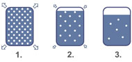
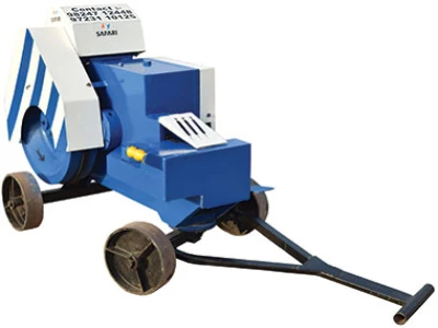
Figure 1: Decreasing of the filling level in bag due to de-aeration.
If the bag filling is done directly after blending, most of the air which was added to the pigments during this process, will be filled into the bags together with the pigments.
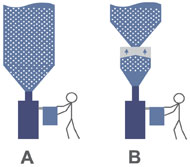
Figure 2: Installation of a pre-hopper for de-aeration of pigments or powders before filling in bags.
Consequently the de-aeration of the pigments or powders before feeding into the bag filling systems is of huge interest of the pigment and powder production industry and its customers. The installation of pre-hoppers is a promising approach to answer to this interest.
Figure 2 shows a common arrangement of bag filling machines in the pigment industry (A). The bag filling machine is installed directly downstream of a blender or huge silo. With this arrangement all air which was added to the product for blending or other process will be filled together with the product into the bags.
Figure 3: Basic working principle of pre-hoppers for de-aeration.
The basic working principle of pre-hoppers for de-aeration (Figure 3) is as following:
- Filling of pre-hopper.
- Filling stop, de-aeration of material during a certain resting time and discharging into bag filling machine.
- Filling start and continuing of discharging into bag filling machine.
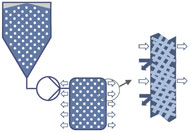
Figure 4: The inverted filter principle of valve bags.
Whereas a de-dusting filter is working due to under-pressure (with reference to atmospheric pressure) inside the system, an effective valve bag filling system for filling of pigments or powders is working due to overpressure inside the bags.
Porous or perforated bag materials allow air to escape from bag inside to outside due to the pressure difference between bag inside and outside, whereas the solid particles can't pass the thin drains (Figure 4).
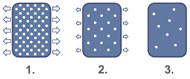
Figure 5: De-aeration during filling of bags.
Figure 5 illustrates the main advantage of a porous or perforated valve bag compared with an open mouth bag.
- A high percentage of the air - captured in the bulk material - can escape during the filling process due to the overpressure in the bag.
- A further percentage of air will escape during a short filling brake after filling of 90% of the target weight.
- Only a small certain percentage of air will remain in the bag after finishing of the filling process. The amount of air depends on the properties of the bulk material and the properties of the bag.
The HAVER M Series Filling Machines with Horizontal Impeller Filling System are designed to fill pigments or other powdery bulk materials into valve bags, where at the filling system is creating an overpressure inside the bags during filling.
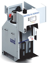
Figure 6: Basic design.
The design of the HAVER M Series Filling Machines considers modularity and scalability, in order to provide the most productive and economical solutions for different requirements. In case requirements change after a certain operation time filling capacities can be increased by installing additional machines. Manual operated systems could be automated by installing automatic bag placers. Ultrasonic Sealing systems could be installed later for automatic sealing of the bags.
According to Figure 6 the entire valve bag filling systems consist of:
- Pre-hopper, to ensure first de-aeration of the bulk material before feeding into the filling machine.
- Impeller system, to feed bulk material into the valve bags.
- Impeller drive, variable speed as an option for filling of different kinds of bulk materials.
- Scissor valve, for dosing of the bulk material into the valve bags. Valve bags are weighed during filling.
- Filling spout, to connect the valves of the valve bags with the filling system.
- De-dusting system to minimize dust emission.
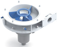
Figure 7: The impeller system.
- the impeller system material
- the impeller diameter
- the impeller bleeds number and design
- the impeller speed and
- the filling channel diameter, according to bulk materials and valve bags properties.
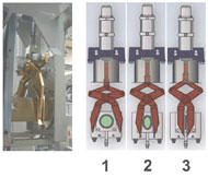
Figure 8: The scissor valve.
The scissor gate guarantees an exact dosing of the filling flow rate during fine flow, which results in best weighing accuracy.
Three positions of the scissor gate are controlled by the HAVER MEC control system via a three-position pneumatic cylinder:
- Course flow, 100% open.
- Fine flow, the opening can be adjusted manually according to the bulk material properties.
- Closed.
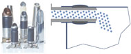
Figure 9: The filling spout.
Various designs are available to be chosen according to the bulk materials properties and the valve bags properties and dimensions.
Filling spouts with inflatable sleeves guarantee a material tight and overpressure tight connection of the valve bags with the filling system, which results in a dust emission free filling and compact bags.
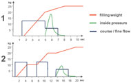
Figure 10: The Dosing, Weighing, and Filling Process.
- High material flow and no filling interruption, for materials with less contained air and bags with high de-aeration capacity.
- Low material flow and two filling interruptions, for materials with much contained air and bags with low de-aeration capacity.
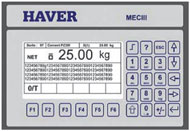
Figure 11: The HAVER MEC Control System.
- filling weight
- material flow (kg/s) by impeller speed and sequence
- course and fine flow amount
- sequence and duration of fluidization.
 Guido Neu, Technical Expert, HAVER IBAU INDIA Pvt. Ltd.
About Author: Guido Neu is a mechanical engineer with over 25 years of experience in different industries such as automotive, recycling, and packaging. He joined HAVER & BOECKER in 1995. After serving as project manager in the chemical division, Guido was coordinator at HAVER & BOECKER African cement division. Currently, he is stationed in Vadodara where he is responsible for the business development of HAVER IBAU INDIA, the 100% Indian subsidiary of HAVER & BOECKER.
Published on:
25 July 2016
Published in: NBM&CW July 2016
Share:
We Value Your Comment