Brijesh Wala, Engineer, NHIDCL

Tunnel Ventilation System Basic Concepts and Designing Principles
The term ventilation combines several functions such as smoke extraction, pollution ventilation, and ventilation for environmental purpose. The design of a ventilation system is usually based on three scenarios:
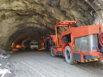
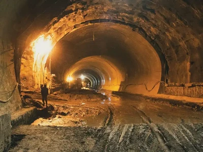
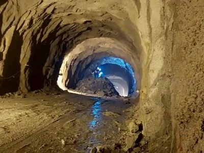
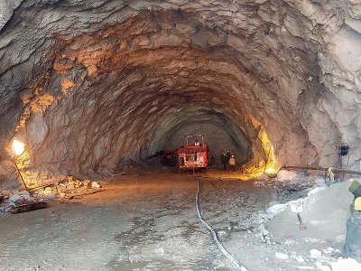
  • During construction: to provide external fresh air required to dilute the pollutants produced by the machines and by blasting used during different construction stages to allow a safe environment for workers working inside the tunnel.
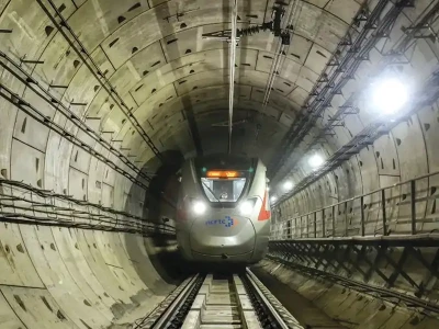
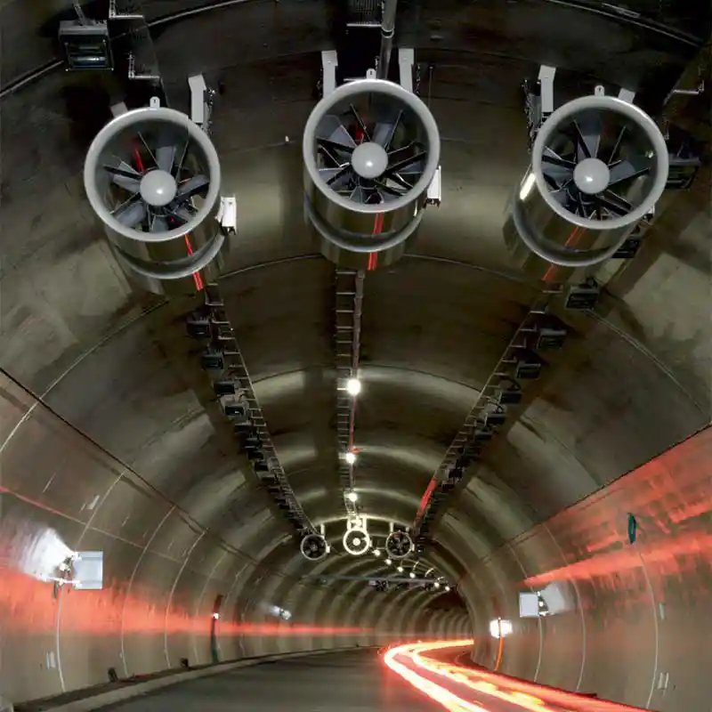
  • During normal operation of the tunnel: this factor is dominant for tunnels subject to high traffic load and frequent congested traffic. The normal functioning of the ventilation system should also ensure prevention of dust from outside entering the tunnel.
  • During emergencies like fire etc: This factor is usually dominant for non-urban tunnels and highway tunnels.
India does not have a specific national regulation for the ventilation of road tunnels. IRC: SP:91-2019 – Guidelines for Road Tunnels provide a brief insight on different types of tunnel ventilation systems and certain design parameters. Permanent International Association of Road Congresses (PIARC) is a standard regulation usually referred while taking values of emission data during normal operations. However, PIARC does not define a special ventilation system for a certain tunnel configuration, whereas an Austrian guideline RVS 09.02.31 determines a special ventilation system for certain tunnel and traffic conditions. Tunnel ventilation system during emergency cases is generally based on RVS 09.02.31, RVS 09.02.32 and NFPA 502.

Types of ventilation systems and factors affecting choice of a ventilation system for a tunnel
As per IRC: 91-2019 – Guidelines for Road Tunnels, RVS 09.02.31, NFPA 502 and PIARC recommendations, there are different types of ventilation systems based on different mechanisms as explained below:

Natural or non-mechanized ventilation system
It can be induced by air temperature and meteorological conditions or by traffic flow. This system involves no installation of fans for mechanical airflow in the traffic zone. In tunnels, there is always some kind of natural ventilation driven by various factors such as atmospheric conditions viz. wind, pressure difference between portals, some chimney or convective effect and traffic. The schematic diagram showing factors affecting natural ventilation inside the tunnel is shown in Figure 1.

Natural Ventilation SystemFigure 1: Natural Ventilation System

Longitudinal ventilation system
This system is generally selected for unidirectional tunnels with length varying from 500 to 4000 m and light traffic density. Among the mechanized ventilation systems, this system is the easiest and cheapest ventilation systems. Longitudinal ventilation is accomplished by using jet fans by accelerating a small pocket of the air present in the tunnel, through an exchange of momentum, are able to induce, on the overall air inside the tunnel, a movement in the desired direction. A schematic diagram of longitudinal ventilation system is shown in Figure 2.

Longitudinal ventilation systemFigure 2: Longitudinal ventilation system.

Semi-transverse ventilation system showing normal and emergency operation protocol

Semi-transverse ventilation system showing normal and emergency operation protocolFigure 3: Semi-transverse ventilation system showing normal and emergency operation protocol

As per RVS 09.02.31, the longitudinal velocity of air inside the tunnel arising due to meteorological conditions and traffic flow should not exceed 10 m/s. Also, to raise the operational safety under the fire effects and minimize turbulence, the fans and ventilators shall be deployed over the length of the tunnel.

Semi-Transverse ventilation system
In this system, the air supply is introduced via the tunnel portals while the exhaust air is extracted over the length through equally spaced smoke extraction dampers throughout the tunnel. The extracted air flows via overhead duct outside the tunnel. In the reversible semi-transverse ventilation system, fresh air is introduced via ducts and the exhaust air flows longitudinally to the two portals.

This system uses a combination of jet fans and axial flow fans. The maximum longitudinal velocity of air flow should be 10m/s as per RVS 09.02.31. The smoke-extraction dampers shall be opened fully in the area of the scene of fire and other dampers shall be closed. The schematic diagram showing semi-transverse ventilation system is shown in Figure 3.


Fully transverse ventilation system
With fully-transverse ventilation system, supply air is introduced, distributed all over the length of the tunnel, and exhaust air is extracted. The air streams (injected fresh air and extracted exhaust air) create a flow in the main tube, in transverse direction to the longitudinal axis of the tunnel. Longitudinal air flow in the tunnel is difficult to control, hence, the independent ventilation sections are created in which fresh air injection and exhaust air extraction can be operated separately. A butterfly flap is installed between two ventilation sections to separate them.

In the emergency mode, the smoke extraction dampers in the fire area are opened and the remaining dampers are closed and smoke is evacuated through the ceiling which is the reason that this ventilation system is suitable in very long tunnels. The schematic diagram of fully transverse ventilation system during normal and emergency operation is shown in Figure 4.

Fully-transverse ventilation system during normal and emergency operation

Fully-transverse ventilation system during normal and emergency operationFigure 4: Fully-transverse ventilation system during normal and emergency operation

Certain factors need to be considered while selecting and designing a particular type of tunnel ventilation system:
  • Cost Effectiveness – As regard to the economic considerations, 20 years is anticipated as the service life of electric machine parts and fittings as per RVS 09.02.31.
  • Safety Analysis during operation.
  • Heat Release Rate (HRR) of fire: It is expressed in megawatts as it is the rate at which energy is released by fire. It depends on types of goods passing through tunnel and flammability. Tunnels in India are generally designed for 50 MW. HRR ratings for tunnels as per different specifications is mentioned in Table 1.
  • Traffic data: Unidirectional traffic, bidirectional traffic, maximum traffic flow, Passenger Car Unit (PCU), no. of petrol/diesel vehicles, vehicular emissions and admissible contamination (levels for CO, NOx, etc.).
  • Geometric Data: Length of tunnel; gradient of tunnel; cross-sectional area of tunnel; altitude of tunnel; meteorological and geographical data such as latitude, air density, relative humidity, wind velocity, etc.
Table 1: HRR rating as per different guidelines
Fire HRR for Different Guidelines
Guidelines NFPA 502 PIARC BD 78/79 IRC SP 91-2019
Types of Fire Load Heat Release Rate (MW) Heat Release Rate (MW) Heat Release Rate (MW) Heat Release Rate (MW)
Passenger Car 5-10 5-10 5 Types of goods Passing through the tunnel & Potential flammability, this is generally 50MW Minimum. 
Light duty Vehicle 10-20 15 15
Coach & Bus 20-30 20 20
Lorry & Heavy Good Vehicle 70-200 30-50 30-100
Design Limit Values
Fresh air requirement: As per IRC: SP:91-2019, minimum fresh air requirement for normal traffic condition might be small. However, ventilation system shall be designed to accommodate sudden demands for high emitting Heavy Goods Vehicles and in that case, an air-exchange rate of at least 4 times per hour shall be considered.

Carbon Monoxide (CO) concentration: As per RVS 09.02.31, a maximum design limit of 100 ppm for CO concentration shall be considered. However, tunnel shall be immediately barricaded if:
  • CO levels ≥ 100 ppm for a period of more than 10 minutes.
  • CO levels ≥ 150 ppm.
Nitrogen dioxide (NO2): According to IRC: SP:91-2019, it is recommended to permit a maximum average in-tunnel concentration of 1 ppm along the length of the tunnel at any one time. For a short-time working exposure a limit of 5 ppm is recommended.

Particulate Matter (PM) emissions: The presence of PM in the tunnel reduces the visibility inside the tunnel. Visibility is reduced by the scattering and absorption of radiation in the visible wavelength range. The tunnel ventilation system must provide visibility levels that exceed the minimum vehicle stopping distance at the design speed. PIARC recommendations provides design and operation values of extinction coefficient for visibility.

General Technical specifications of different equipment of ventilation system and functional testing procedure during operation
RVS 09.02.31 describes a detailed section on technical specifications that are to be observed in all the components of ventilation system including exhaust fans, jet fans, ventilation ducts and auxiliary equipment. All the equipment (fans, auxiliary equipment and cabling) to operate in flue gas conditions (fire), and they must continue to operate at a temperature of 400˚C over a two-hour period. Jet fans in longitudinal tunnel, shall be spaced at a distance of ≥ 200m, a temperature stability of 250˚C over a 60-minute period.

Jet fans: All jet fans including mountings, and sound absorbers, shall be manufactured from corrosion-resistant material. The jet fans shall be mounted in a way which limits vibrations.

Jet fans mounted on proper supports on the side walls of the tunnelFigure 5: Jet fans mounted on proper supports on the side walls of the tunnel

Axial fans: Axial fans comprise of fan with a wheel, guide wheel and electric motor, as well as nozzle, diffuser, shut-off valve. Provisions shall be made to monitor vibrations in the fan motor unit and temperature of coil and bearings. The quantity of air discharged and the change in pressure in the fans must be recorded regularly and proper documentation of reports shall be done. The fans shall be usually located in portal stations or caverns and it should be ensured that proper access is available and its maintenance should not hamper the traffic flow.

Smoke Dampers: These assist in the targeted regulation of the exchange of air between the carriageway and the exhaust air ducts. The dampers shall perform satisfactorily in the transverse ventilated tunnels both during normal operation and in the case of fire. The desired width of the dampers shall be 3 m and the minimum quantity of exhaust air of 120 m³/s flows through the dampers in the event of fire.

Functional testing of ventilation system
Tunnel Ventilation System Basic Concepts and Designing Principles
Regular testing during Operation and Maintenance period as mentioned below shall be conducted on site in accordance with RVS 09.02.31.

Monthly testing: All the equipment including fans, ventilators, dampers shall be inspected monthly as regards to their functionality and under all volume flows and damper positions.

Annual functional testing: This shall be carried out together with the annual visual inspection with the aim of inspecting and reporting this back to the central control system.

Every six years: suction tests involving volume flow measurements shall be performed in order to examine the minimum exhaust air volume flow required at every smoke damper.

Overview of Ventilation System to be adopted in Z-Morh Tunnel Project Brief
Z-Morh Tunnel is located in the UT of J&K. It is a 6.426 km long tunnel with 6.412 km parallel escape tunnel. The West Portal (Srinagar side) is at an elevation of EL 2489 m and East Portal (Sonamarg Side) is at an elevation of EL 2634 m. The slope of the tunnel is rising from Srinagar to Sonamarg side at 2.27%. The maximum overburden for the tunnel is 1075 m. The main tunnel is connected with escape tunnel with motorable cross-passages at every 750 m and pedestrian cross passages at every 250 m. There is a ventilation adit of length 575 m in the middle of the alignment of the tunnel. The general tunnel layout showing main and escape tunnel is as per Figure 8.

General tunnel layoutFigure 8: General tunnel layout

Traffic forecast and Fire-design data

The key traffic data is as follows:
  • Bidirectional traffic in main tunnel.
  • 2 lanes, 1 lane per direction.
  • Design speed – 80 kmph.
  • Peak hour traffic: 1070 vehicles/hour.
  • The percentage of diesel cars in India is highly variable and hence it is assumed that the diesel share in the running fleet is 35%.
  • Fire rating: 50 MW.
Selection of ventilation system
Based on the selection criteria presented in section 2, a semi-transverse ventilation system will be used in the Z-Morh Tunnel. The advantage of semi-transverse ventilation over fully-transverse ventilation system for long tunnels is the relative simplicity of the system, lower cost and ease of maintenance. The general layout of ventilation system is shown in Figure 9.

Layout of ventilation system - Longitudinal sectionFigure 9: Layout of ventilation system - Longitudinal section

The main characteristics of the ventilation system are:
  • Normal operation with exhaust extraction though ventilation station at the center of the tunnel. The jet fans installed at the portals equilibrate the flow conditions in case of asymmetric traffic.
  • Concentrated smoke extraction at the fire location through the exhaust duct in case of fire.
  • Motorized smoke-extraction dampers installed in the false ceiling allow for a precise localization of the smoke-extraction zone. Jet fans control the airflow in the tunnel for achieving an optimum smoke extraction. Smoke is ejected through the ventilation station.
  • Smoke discharge through the closed portal in case of fire in the vicinity of a portal, in the section without false ceiling.
  • The extraction duct is interrupted in the portal areas. This allows for optimum installation of large jet fans.
  • The remaining jet fans are installed in the lay-bys.
Layout of ventilation system - Top viewFigure 10: Layout of ventilation system - Top view

The main components of the main tunnel ventilation system are:
  • Ventilation station in the middle of the tunnel with 3 large-diameter exhaust fans.
  • Exhaust duct in the upper part of the tunnel cross section, interrupted at the portals for allowing the installation of jet fans.
  • Remotely controlled motorized dampers for exhaust and smoke extraction in the exhaust duct, installed at regular distances of about 100 m (shorter distances apply at the ends and centre of the exhaust tunnels, where dampers are located with a distance of about 25 m).
  • Remotely controlled vertically mounted motorized dampers in the exhaust duct, separating the West and the East side from the smoke-extraction station.
  • Jet fans distributed along the tunnel length.
  • Ventilation sensors (pollution sensors and anemometers).
Conclusion
Tunnel Ventilation System plays an integral role in the stability and functionality of tunnels after construction. The ventilation system should be designed with due diligence and taking proper care of all the parameters and standard international codes mentioned above. Any compromise in the ventilation system may result in hazardous situation inside the tunnel. There have been instances where due to failure of ventilation system and fire-fighting system, a huge catastrophic damage has occurred. Salang tunnel accident in Afghanistan is one such example.

As mentioned earlier, India does not have any specific regulation for tunnel ventilation system, hence, experiences from different road tunnels shall be compiled and shared at appropriate platform for future reference and an eternal guidebook. This will increase the expertise of Indian professionals in this field and reduce the reliance on foreign expertise while designing ventilation system for Indian tunnels.

The tunnel ventilation system should be maintained adhering to all the standard technical specifications. To avoid any negligence by the Operation & Maintenance (O&M) Contractor during operation of the tunnel pertaining to the safety of the ventilation system and E&M installations, contractual provisions shall be included for penalizing the Contractor for such practices.

References
  • IRC: SP: 91-2019 – Guidelines for Road Tunnels.
  • Austrian standard RVS 09.02.31, “Tunnel equipment – ventilation – basic principles”, 1st of august, 2008.
  • Standard NFPA 502, USA, “Standard for road tunnels, bridges and other limited access highways”, 2011 Edition.
  • PIARC Committee on Road Tunnels Operation (C3.3): Systems and equipment for fire and smoke control in road tunnels (2007).
  • PIARC Technical Committee on Road Tunnel Operation (C5): Road Tunnels: Vehicle Emissions and air demand for ventilation (2004).
Sela Tunnel Project - Overcoming The Impossible
The responsibility for construction and maintenance of Balipara-Charduar-Tawang (BCT) Road has been entrusted to Border Roads Organisation (BRO). The 317.520 km long road connects West Kameng and Tawang districts of Arunachal Pradesh to the rest

Read more ...

Slurry TBM ‘Channel Express’ launched by CRCHI for working in Water Supply Tunnels in Singapore
On February 1, 2023, CRCHI attended the launching ceremony of its Slurry TBM ‘Channel Express’. It will be used in the construction of key water supply tunnel project TWRP Pipeline Contract 1 in Singapore where it will bore 1.6km with the inner diameter

Read more ...

China’s Largest TBM - With Panda Face Emerges From Tunnel
On 12 December 2022 ‘Jinxiu’ - China’s largest EPB TBM developed by CRCHI - marked the first smooth breakthrough of the Jinxiu Tunnel, a key control project of the Chengdu-Zigong high-speed railway. Jinxiu is China’s largest diameter EPB TBM with

Read more ...

STRUCINSPECT Technology Transforms Inspection of Los Angeles Metro Tunnel Network
With drones, multispectral optics, and AI, Austrian joint venture transforms tunnel inspection in the US. The world’s first infrastructure lifecycle hub taps the rapidly growing global market for infrastructure inspections. The remarkable thing about

Read more ...

CRCHI showcases total solutions of Underground Engineering Equipment
China Railway Construction Heavy Industry Corporation Limited (CRCHI) brought the whole industry chain products and solutions to bauma CONEXPO INDIA 2023. CRCHI exhibited TBMs, drilling and blasting method equipment, cotton pickers, and other

Read more ...

Sandvik sets up new factory; hands over first ‘made in India’ tunnelling jumbo to KSR Group, Hyderabad
In a historic event held on 30th January, 2023 Sandvik proudly presented the key of the first ‘made in India’ DT820 Tunnelling Jumbo to Mrs. and Mr. Koneru of KSR Group, Hyderabad. The machine was rolled out from Sandvik’s newly set-up state-of-the-art

Read more ...

CRCHI Slurry TBM ‘Avni’ Helps Make a Breakthrough in Bangalore Metro Project
The 6.6m Slurry TBM developed by CRCHI exited the tunnel at Vellara Station, Phase II of Bangalore Metro in India, becoming the first TBM to complete the breakthrough for the whole line of the project. Avni is one of the four slurry TBMs provided by CRCHI

Read more ...

The Bolter Miner - A Technology Revolution for Roadway Development in Underground Coal Mining
In India, coal is still the primary source of energy; over the past few years, there has been quantum jump in coal production level, but it was mostly due to the high percentage share from the opencast sector. The country is witnessing a fast

Read more ...

CRCHI emerges as provider of total underground engineering equipment and solutions
China Railway Construction Heavy Industry Corporation Limited (CRCHI) showcased its comprehensive range of equipment and products at bauma that included solutions for the whole industry chain in the field of

Read more ...

Herrenknecht AG wins bauma Innovation Award 2022 for development of continuous tunnelling
Herrenknecht AG won the highly coveted award bauma Innovation Award 2022 in the category “Machine Technology” for the new development of continuous tunnelling. The award was given for the next innovation boost in the mechanized

Read more ...

The Genesis of Underground Engineering
Regardless of the tunnelling technology used, tunnel designers decide the future success or failure at an early project stage. In fact, designers are the real managers of tunnel construction. The choice of design together with selected contract model is

Read more ...

Managing Geological Complexity in BVC and PAC of Tehri PSP, India - A case study
Tehri hydroelectric project is located on the left bank of River Bhagirathi in the state of Uttarakhand. Tehri Pumped Storage Project (PSP) comprising 4 Nos of reversible pump-turbine units of 250 MW each, involves construction of an underground Machine Hall

Read more ...

TBM driving under low overburden by adopting innovative methodology
TBM mining in urban areas particularly under low overburden (less than 0.5D, D = tunnel Dia) is a big challenge to design team as well as execution team. While working in a Lucknow metro project, the metro authorities encountered a stretch where TBM had to cross

Read more ...

CRCHI Mega Slurry TBM ‘Jinghua’ Assists the First Tunnel Section Breakthrough of Beijing East Sixth Ring Road Reconstruction Project
In September 2022, the Beijing East Sixth Ring Road Reconstruction Project reported another good news: the CRCHI mega slurry TBM ‘Jinghua’ smoothly reached the intermediate air shaft, marking the project’s achievement. The maximum excavation diameter

Read more ...

TERRATEC EPBMs ready to tackle Kanpur Metro’s 1st Underground Section in India
TERRATEC celebrated the successful site acceptance testing of two 6.52m diameter Earth Pressure Balance Tunnel Boring Machines (EPBMs) for Uttar Pradesh Metro Rail Corporation (UPMRC) for Corridor-1 of Kanpur MRTS Project (KNPCC-05) in India. The two 6.52m

Read more ...

Tunnelling Asia 2022 - International Conference on Underground Space
Tunnelling Asia 2022, organized by TAI, which took place in Mumbai during 27th and 28th June, saw a huge gathering of delegates/engineers from all around the world. The theme of the conference: ‘Underground Space: Need of the Day’ focused on

Read more ...

Hydraulic Heave Failure Mitigation Approach for the construction of the Deepest Metro Ventilation and Egress Shaft in India
Dr. Lakshmana Rao Mantri, Assistant General Manager (Designs), and Satya Narayan Kunwar, Project Manager, AFCONS Infrastructure Ltd. , discuss the design and construction challenges of constructing India’s deepest underground metro ventilation

Read more ...

Creating Zero-Carbon Tunnels
Despite a daunting timeline set by the Paris Accord, zero-carbon tunnels are within reach, provided the right solutions are implemented. Er. Vasileios (Bill) Paoulos, CMT, CMRL, L&T Construction Heavy Civil Infrastructure

Read more ...

Readily Biodegradable Soil Conditioning Foaming Agents - A New Technology
Mike A. Sposetti, Global Technical Manager TBM, Underground Construction, Master Builders Solution, Malta, and Manish Gautam, Product Segment Manager - UGC TBM Tunneling Projects, Master Builders Solution, Mumbai, discuss how readily biodegradable

Read more ...