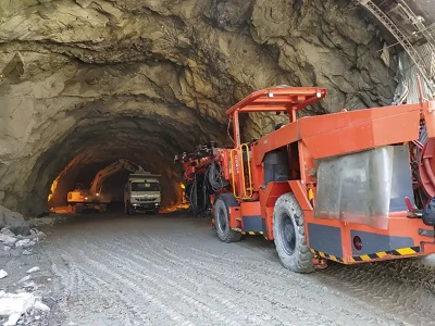
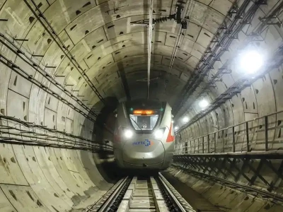
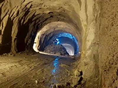
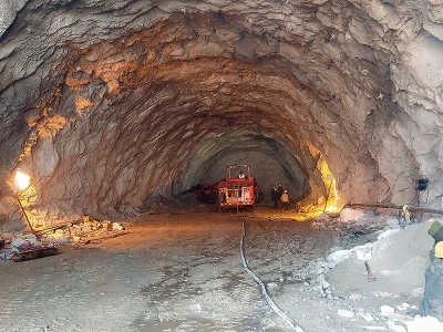
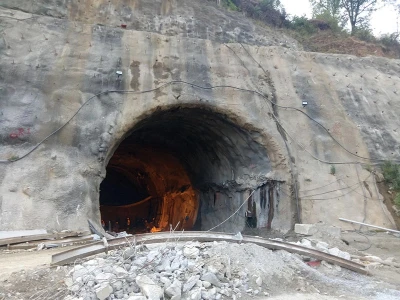
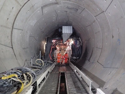
TBM driving under low overburden by adopting innovative methodology
TBM mining in urban areas particularly under low overburden (less than 0.5D, D = tunnel Dia) is a big challenge to design team as well as execution team. While working in a Lucknow metro project, the metro authorities encountered a stretch where TBM had to cross a nallah crossing of 15m length under overburden of <1m. Not only the stability of TBM due to uplift was of concern but stability of both banks of nallah during TBM driving due to possible high-volume loss (%) as the banks consisted of mostly made ground material. Also, most structures on the nallah banks were non-engineering structures whose stability due to vibration of TBM was another concern. Overall looking at all these aspects it was proposed to drive TBM by controlling TBM mining parameters and also adopting an innovative technology to control all possible modes of risks. The proposed method was guaranteed in terms of providing stability to both ground and superstructures and was cost effective and feasible in terms of construction. The whole solution from design to execution was a collaborative approach between client, contractor, and designer. The total process took 15-18 months to take shape. I was working as a design representative to the project’s contractor.
Published on:
07 November 2022
Published in: NBM&CW November 2022
Share:
We Value Your Comment