Micro-Tunnelling Machines for Pipe Roof Support Construction

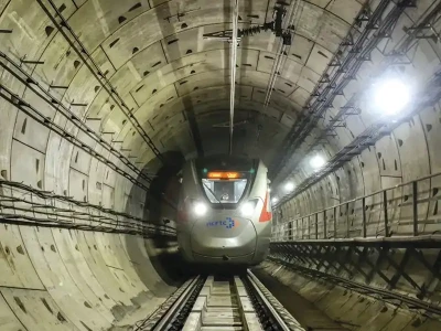
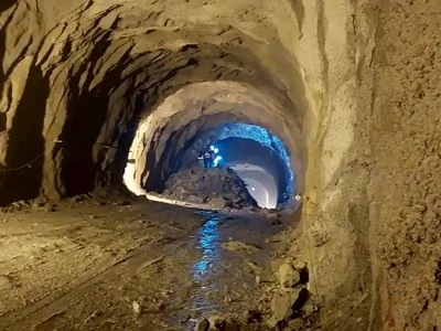
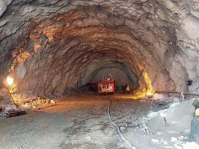
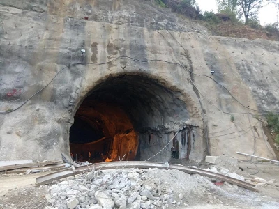
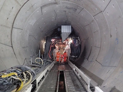
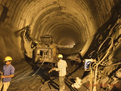
Diwakar Velu and Kim Yeow Yap, Land Transport Authority, Singapore, present a case study on the use of medium diameter (1.2m) pipe roofing for the construction of underground subway entrances (6.4m H x 8.4m W) with span lengths ranging from 40m to 60m, undercrossing two live roadways - Keppel Road & Spottiswoode Park Road. This paper shares the process involved in construction of pipe roof mined support using micro tunnel boring machines comparing the use of both normal & retractable machines.

Diwakar Velu and Kim Yeow Yap, Land Transport AuthorityPicture courtesy: CRCHI

As a form of closed trenching mechanism in underground subway excavation for public transport infrastructure projects, the pipe roofing method is increasingly becoming popular globally, including in Singapore. In pipe roofing, the layout and orientation of pipes are designed to match the shape of the final subway tunnel, and the key purpose is to provide a temporary support during the various stages of construction of the final subway tunnel.

This paper presents a case study on the use of medium diameter (1.2m) pipe roofing for the construction of underground subway entrances (6.4m H x 8.4m W) with span lengths ranging from 40m to 60m, undercrossing two live roadways - Keppel Road & Spottiswoode Park Road. Besides conventional micro tunnel boring machines (mTBM), retractable micro tunnel-boring machines (R-mTBM) were also deployed to execute the works which are mostly located in Jurong Formation with varying soil and rock lithology.

It shares the overall process involved in the jacking of pipe roof support and highlights key comparisons with the conventional mTBMs, gives insights on the process involved in the use of the R-mTBM and detail key considerations to note when planning for the use of R-mTBMs in future projects based on the case study and assessment of the important parameters associated with the operation of pipe roofing works and provide details on the ideal limits for different Jurong Formation conditions where these machines were deployed. The last section of the paper gives details on the lessons learnt and insights on the importance of the ideal launch shaft size, pipe length required, with some references from field instrumentation results on the performance of the jacking operations.

Introduction

Singapore’s Mass Rapid Transit (MRT) system has been rapidly developing in recent years to enhance the connectivity of the existing network and shorten commute time for residents. To achieve this, new underground metro stations are very often situated in heavily populated areas with existing high-rise residential buildings, roads, and viaducts in the vicinity. Furthermore, to establish the connection between the station and the various commuter catchments in the area, underground linkways would have to be constructed.

In the 1960s, the pipe-roof method was first adopted to construct the first Atami tunnel project of the Tokaitou Shinkansen line in Japan (Coller & Abbott, 1994). In 1979, the ‘Antwerp’ technology was proposed in Belgium, and the central station was built successfully using this method (Ire, 1985). With the increased popularity of the pipe-roof method, many countries including Singapore, Malaysia, the United States, South Korea have successively adopted this method. The pipe-roof method evolved from the pipe umbrella method, which was adopted in shallow ground cover and harsh ground conditions in underground construction (Wang et al., 2017). The shallow structures pose great concerns in terms of tunnel deformation and ground settlement. Hence, it becomes very critical to choose the correct construction method and the machinery to be adopted to manage the tight and challenging urban conditions.

As a pre-support-system, the pipe-roof method has been popularly adopted because of its many advantages, including minimal impact on the surrounding environment, simple construction technology, and high construction safety (Schumacher & Kim, 2013). Construction of underground tunnels for pedestrian linkways using micro tunnelling to form pipe roof box using micro tunnelling machines has become common in the recent past. The pipe roof which is installed by pipe jacking (prior to excavation) creates an advanced roof support system. It forms a structural part of the ERSS and reduces the stress relaxation in soil.

Micro Tunnel Boring Machines (mTBM)

mTBMs are used to carry out the jacking operation. Traditionally, open-cut excavation methods were used for most of the subway projects. However, these methods are disruptive and can cause a lot of surface disturbances as they may involve traffic diversion/realignment and advance utility diversion over the length of the subway. The use of mTBM is well suited to urban environments where disruption at ground level is confined to the launch and reception shafts. In addition, the recent advances in guidance systems and tunnelling equipment have also enhanced the construction approach - one of which is the adoption of the retractable micro tunnel boring machine (R-mTBM) which eliminates the need for reception shafts. The performance and advantages along with the limitations are shared in this paper.

Project Description

The Circle Line (CCL) comprises 33 stations, of which 30 have been completed and are in operation. The Circle Line 6 (CCL6) project will add the remaining 3 stations and a depot to the Circle Line, forming a complete loop. The 3 stations of CCL6, viz. Keppel Station, Cantonment Station and Prince Edward Road Station will connect the existing Harbourfront Station to Marina Bay Station. This paper is based on the construction of CC31 - Cantonment Station. The proposed Cantonment Station has four entrances planned at strategic locations to serve the stakeholders in the vicinity of Keppel Road, Spottiswoode Park Road and Everton Road.

As the Cantonment station is located at a site that has mixed ground conditions, this presents greater challenges during construction of pedestrian linkways from the entrances to the station. Three of the entrances are connected to the station by underground linkways from the concourse level of the entrances. These underground linkways are constructed using trenchless construction method adopting Pipe roofing and mined tunnel methods to minimize disruption on the surface to stakeholders.

The works comprise of a 108m linkway next to the existing Tanjong Pagar Railway Station (TPRS), one linkway which runs beneath the Keppel Viaduct and two linkways which run across to Spottiswoode Park Estate along with a centralized cooling tower. The overall jacking length summarizing all pipes are indicated in Fig 1. The figure also shares the typical section comprising of Horizontal (H) and Vertical (V) section of the pipe-roof support structure to be adopted for mining once all pipes are jacked. A total of over 5000m of pipe jacking is done to facilitate the construction of the linkways.

Diwakar Velu and Kim Yeow Yap, Land Transport AuthorityFigure 1: C883 Cantonment Station Linkway Overview and Summary of Jacking Works

Geology and Ground Profile

The overall geological condition for this station is in varied Jurong Formation layers of SIII, SIV, SV. The linkways are shallow and most of the ground encountered was anticipated except for Entrance 1 along the Keppel Road, where a mixture of soft ground conditions mostly in estuarine clay and fill for the 50% of the linkway was encountered. Due to this, the entire mined linkway had to be pre-grouted. The geological summary for the 4 entrances is summarized in Fig 2.

Diwakar Velu and Kim Yeow Yap, Land Transport AuthorityFigure 2: Geological Summary of Linkway and Centralized Cooling Tower

Micro Tunnel Boring Machine (mTBM) Operations

This section shares the process involved in the operations of normal and retractable machine citing examples from the jacking operations obtained from the use of two different machines. The typical pipe jacking works for linkways involve the setting up of the pipe roof pre-support using slurry mTBMs. Considering the geological condition, a mixed face cutter head with disc cutter was deployed for the jacking operations.

Normal mTBM

Two normal mTBM were used to perform the construction linkways entrances 1 and 2. This machine requires the operations to be done from two independent shafts to facilitate the launching and retrieval of the machine. During the advancement of the pipes, bentonite is pumped to the external surface. This helps to lubricate and reduce frictional force of the pipe against the ground and to provide support to the ground to prevent settlement. The excavated material is removed from the front of the cutterhead via a slurry circuit, which is sent to a separation plant for processing.

Diwakar Velu and Kim Yeow Yap, Land Transport AuthorityFigure 3: Comparison of Normal Vs Retractable Process

Located near the launch shaft, the separation plant removes the excavated material from the slurry through a multi-stage process. The plant is used in conjunction with the mTBM to clean and recycle the slurry, thereby increasing its service life. Once the pipes are jacked, they are retrieved from the jacking shaft, serviced, and relaunched again. Simultaneously, for the completed drive, the annulus gap grouting is done to prevent settlement between the ground and the pipes. The pipes are backfilled using cement grout once all the pipes are completed. Typically, both ends of the pipes are capped and grouting is carried out through a pre-installed pipe. At the reception site, a bleed valve was attached to bleed air while pumping grout from the launch site.

Diwakar Velu and Kim Yeow Yap, Land Transport AuthorityFigure 4: Entrance 3 –Retractable Machine Steps and Details

Retractable mTBM

On the other hand, 2 retractable (R-mTBM) machines were deployed to complete the linkway Entrance 1 and centralized cooling tower. The entire process of the jacking operation is like the normal mTBM except for the unique feature of being able to be retrieved/ pulled back and redeployed. Here, the machine is launched from the launch shaft and retrieved once they reach the station.

When the mTBM is pulled back, the cutting wheel needs to be smaller to be pulled back to the launch shaft. To accomplish this, all the cutter bits of the cutter periphery are folded inwards, thereby reducing the diameter of the cutting wheel. The above depicts the process of pulling the machine within the pipe and once it is retrieved the machine is redeployed again for the subsequent. This results in a direct reduction in cost, manpower and time arising from the elimination of the reception shaft.

Case study: Retractable mTBM Performance

Despite the merits, one of the common factors and key considerations on the choice of machines depends on the geological conditions and the site constraints. The following sections give the comparative study and findings from the pipe roofing process, based on the data collected from jacking operations and instrumentation records.

Performance assessment comparison normal vs retractable

To assess the details on the performance of the two types of machines, the key parameters pertaining to the machines in different entrances were considered. The considered parameters include the Thrust, Speed, and Torque obtained from the driving records and plotted in the graph to get an overall review, as shown in Figure 5.

Diwakar Velu and Kim Yeow Yap, Land Transport AuthorityFigure 5: Comparison normal and retractable performance

Due to the foldable cutter wheel, the torque limits for the retractable mTBM are lower compared to the normal mTBM. Average for a normal mTBM ranges between 35~50 KNm (average of around 45KNm) compared to that of the R-mTBM which ranges between 20~35 KNm (average of around 25KNm).

Figure 5 represent the performance of the machines under the difference geological conditions. This shows the achievable Thrust and advance rates managed during the drives under stiff and soft clay conditions based on their performance in Entrance 1 and Cooling Tower. The performance of retractable mTBM is noticed by well managed. The productivity can be further increased by designing more roboust cutting wheel in future that can be best solution for such conditions with the elimination of retrieval shaft.

Diwakar Velu and Kim Yeow Yap, Land Transport AuthorityFigure 6: Entrance 3 Drive Record and Soil log

Retractable mTBM challenges

The following sections give more details on the challenges while the machine was deployed at linkway Entrance 3 which had varied geological conditions over the 98m. The thrust force is taken as a key parameter to compare and explain the performance of the machine. The figure 6 represents the drive record of jacking for the first drive.

Diwakar Velu and Kim Yeow Yap, Land Transport AuthorityFigure 7: Entrance 3 overall Jacking Summary

Performance of R-mTBM at Entrance 3

We can note that this pipe roof had to go through a varied and mixed geological condition. The performance analysis indicates that the initial stages of jacking works at certain stretches, especially between 55-80m machine had difficulty to drive through SIII formation. The penetration rate along these stretches were slow, ranging from 1-6mm per minute, which resulted in longer jacking time.

The advanced speed indicated that at soft sections the maximum speed achieved was equivalent to about 20 mm and lowest about 2-5mm as it was difficult to grind through the SIII sections. The final section of the drive also had low speed due to the limiting torque and sticky conditions of clay. In addition to the above, the long sections of the pipe also resulted in the machine needing more thrust. Increased thrust resulted in frequent jams. With the cutter hinge and lower torque limits, the thrust had to be managed to drive without stoppage.

Diwakar Velu and Kim Yeow Yap, Land Transport AuthorityFigure 8: Problems of Cutter Head Jammed (Stiff Clay) and Cutter Head Damage (SIII)

Cutter Tools Impact and Enhance- ments – Horizontal pipe sections

However, over time this resulted in the breaking of the disc cutters, requiring interventions from within the pipe. Figure 8 indicate the extent of the problem and interventions done to free the cutter head due to the sticky and hard rock conditions.

Diwakar Velu and Kim Yeow Yap, Land Transport AuthorityFigure 9: Entrance 3 – Horizontal Drives- Thrust Force Trend and Cutter Head Damages

The graphical comparison for the thrust force in Figure 9 shows that the initial drives had very high thrust force, which also resulted in high contact forces which caused the rings to split. Interventions within the pipe had to be done to repair causing delays.

Diwakar Velu and Kim Yeow Yap, Land Transport AuthorityFigure 10: Entrance 3 - Horizontal Drives thrust force trend post modifications

To enhance the performance, tungsten type cutter discs were procured and used together with the normal disc cutters as shown in figure 10 in the cutter head comparison. This modification with mixed tools was helpful in mining within the hard strata. The tungsten discs were replaced to the gauge area to enhance its performance and maximize its usage, the speed however didn’t improve much although it helped the R-mTBM perform better for the remaining drives with no stoppage due to the sudden break of the discs. With this change and modification, the remaining horizontal drive sections were completed without any major stoppages.

Diwakar Velu and Kim Yeow Yap, Land Transport AuthorityFigure 11: Process of involved in the removal of support plate.

Cutter Tools Impact and Enhance- ments – Vertical pipe sections

This was not the same for the vertical sections of the pipe as the thrust forces required to advance the jacking went as high as about 450KN. Also, the pipe friction was higher, and the geological conditions was getting more varying for the vertical section of the pipes. To overcome the issue: a) all disc cutters were replaced with tungsten type, b) retractable hinge connection was being welded with support plate, and c) planned intervention was done prior to docking to remove the support before the R-mTBM was pulled back.

For the item (b), the retractable hinge of the cutter wheel had to be supported with plates to make it rigid so that the contact force coming on the cutter disc could be controlled well. Due to this weak location while mining in hard stratum there is an uneven force resulting in earlier cutter wear and cutter wheel to get jammed. The approach is such that, prior to commencement of the drive the cutter wheel is modified with the support plate and the machine is launched like a normal machine. It is to note that the support plate welded limits the retraction process as the cutter wheel can’t be folded. Hence, another adjacent pipe intervention is done at the end within the improved ground area to remove this and facilitate the retraction process.

Overall, this process reduced the breakdown and unplanned interventions needed to complete the remaining pipes. Figure 12 shows the performance of the drives after the implementation of the measures. The thrust force was well balanced and returned to the nominal ranges of around 300KN and the other parameters were well controlled within the limits.

Diwakar Velu and Kim Yeow Yap, Land Transport AuthorityFigure 12: Entrance 3 - Modification Vertical Drive

The average time also dropped for the entire length. The average driving time was observed to be about 25 days for B10, B11, B12 and B13, and was reduced to about 23 days for the subsequent drives. It is evident from the performance and experience that the choice of machine is dependent on the ground conditions. Figure 13 depicts the changes undergone by the cutter head over the course of completion of the drives.

Diwakar Velu and Kim Yeow Yap, Land Transport Authority

Case study: Jacking Pipe Size Impacts

Majority of the pipe roof box linkways are constructed under shallow conditions and are adopted due to the presence of roads or utilities within the corridor under tight working constraints. However, this also results in many challenges which may affect the works in terms of productivity and controlling the ground movements. The following section will share some insights on such challenge.

Jacking Shaft and Pipe Length Influencing Jacking Works

One of the other key considerations is the identification of the ideal size of the launch shaft to achieve the maximum productivity. This, in addition to the Retractable-mTBM, could give much more benefits in terms of the overall process. In this contract, due to the space constraint the launching shaft for the jacking operation could accommodate only 3m pipes to be jacked. However, the centralized colling tower and Entrance 3 could accommodate 6-9m pipes due to the larger shaft orientation. It is to be noted that there is significant time savings in terms of time and man hours.

Due to the shorter pipes, there is a significant amount of time lost due to the joint connections which involves the process of preparation and setting up followed by welding the joints and inspections prior to commencing the jacking. For the three activities, the jacking time depends on the geological conditions and might vary for different ground sections. Figure 15 represents the actual time for the three main activities which is taken from the drive records of Entrance 1.

Diwakar Velu and Kim Yeow Yap, Land Transport AuthorityFigure 15: Entrance 1 Jacking Drive Records

For ease of understanding, the estimated time savings for different shaft sized is interpolated based on the various pipe lengths is being tabulated based on the drive records from Entrance 1 shared earlier.

Based on table 1, we can note the increase in pipe length from 3m to 6m for the same jacking length provides about 50 days savings. Alternatively, there is increase in launching shaft size which needs to be assessed based on the site and urban constraints. From the experience 6~9m pipe length is an ideal size for such activity.

Diwakar Velu and Kim Yeow Yap, Land Transport Authority

Jacking Pipe Length influencing Ground Movements

It was also noted from the experience that the ground movements especially when jacking in soft ground conditions had major trends. Due to the repetitive process involved within the influence zone, there is a lot of disturbance especially in the case of horizontal pipe jacking. This is aggravated with the very close stoppage and introduction of dual machines. This section shares the ground movements due to the shorter pipe sections used for Entrance 1 under a mixed soft ground condition. This jacking operations was done with 2 mTBM moving away from the centre. As noted earlier from the geological profile this section consists of sticky clay in the initial part and later stage entering estuarine clay.

To assess the ground movement, ground markers data was taken from the typical array at the initial, middle and the end sections of the drive. Similarly, a graph indicating the advance speed and time taken for all the pipe sections of the drives is plotted.

Based on the field data, we can observe that the influence of the jacking has affected the initial sections up to 30m of the drive where the machine had to pass through sticky clay resulting in a longer time to jack at an average of about 12 hrs for 3m pipe section. On comparing this with the movements, the markers show a dropping trend (A) for LG 9750 close to the launching shaft where the jacking is done within the sticky clay. This is likely due to the longer jacking time and idle time to weld pipe joint as indicated in the previous sections. Due to the shorter pipe sections, there is a lot of disturbance within the same zone causing higher ground movements.

Diwakar Velu and Kim Yeow Yap, Land Transport AuthorityFigure 14 Entrance 1 soil log

The other factor also is the simultaneous jacking using 2 machines which indeed accelerated the settlements as seen in the graph indicating (B), where the trend increases steeply after P4 when both the machines are jacking at the same time within the closed spacing causing more disturbance. However, this is much well controlled as the jacking enters the estuarine clay or soft ground where the settlements are well controlled (C) as seen for the trends LG 9737 and LG 9739. The advance rates are high almost 5 times more than the initial stages and the impact of simultaneous jacking also has less affect.

Overall to reduce the ground movements for jacking operations especially under soft sticky ground conditions more preference should be given to the pipe length, to reduce the overall duration as well to reduce the stoppages. However, for more stiffer conditions when compared to the other entrance situated in Jurong SIII and SIV where the geological conditions are more uniform the settlements are more stable.

Discussion and Conclusion

This paper, on the whole, shared the process involved in the construction of pipe roof mined support using micro tunnel boring machines comparing both the use of normal and retractable machines. Despite the observed limitations, deploying R-mTBM results in substantial cost reduction by eliminating the reception shaft unlike normal machines which need to be jacked and retrieved. The savings could be increased further if the machines are reutilized in projects where there are multiple linkways to be constructed. This provides a Lean solution for such kind of works.

The key aspect based on the field experience is that the retractable machines should be deployed with careful assessment of the geological conditions by having additional soil investigation to better understand the profile and design the machine accordingly. In addition, it is also important to take into consideration the overall jacking length prior to adopting the R-mTBM. Looking at the performance, these machines are handy for smaller linkways and highly efficient in working under soft ground conditions.

Diwakar Velu and Kim Yeow Yap, Land Transport AuthorityFigure 13: Instrumentation Assessment Entrance 1 Vs Drive Summary

This paper also presents the performance rates of the machine in varied Jurong Formation (or similar grounds) which could be used as reference for future works under similar ground conditions. The ideal advance rates are between 10~20 mm for SIV and higher up to 50~80mm for soft clay SVI and Estuarine Clay. The advance rates are about 3~10mm for SIII conditions and stiff/sticky clay conditions. This can be further improved by considering the provision for having some clogging preventions solutions especially for sticky clay conditions.

From the discussion and case assessment on the pipe length, we can conclude that having shorter pipe lengths may result in overall productivity loss and may pose concerns to ground movements. The impact is greater if the penetration rates are lower, and the ground is soft. The ideal situation is to jack the pipes faster and quickly seal them to reduce as much idle time if possible. Hence, the ideal size estimated is to have at least pipe lengths of about 6~10m.

The other important factor to consider when deploying mTBMs is whether twin machines are used for the pipe roof support construction, especially in soft ground conditions. It is evident from the experience that there is impact mainly during the horizontal drives as they are very close to each other. In such situations, it is ideal to space out the mTBM’s operations sufficiently or stagger the drives to control the ground movements. However. this is not as critical for the vertical drives as there is sufficient spacing between the two machines.

Acknowledgements

The authors wish to acknowledge the contributions from the Designers, Consultants, Contractors, and other fellow colleagues of C883 Land Transport Authority Project Team who made this project a success.

References

  1. 1. AECOM Singapore Pte Ltd. Tender Geotechnical Interpretative Baseline Report – Contract C883 – Station CC31, March 2017
  2. Coller, P. J., & Abbott, D. G. (1994). Microtunneling techniques to form an in-situ barrier around existing structures. In High Level Radioactive Waste Management: Proceedings of the Fifth Annual International Conference (Vol. 2).
  3. Schumacher, F. P., & Kim, E. (2013). Modeling the pipe umbrella roof support system in a Western US underground coal mine. International Journal of Rock Mechanics and Mining Sciences, 60, 114–124. Tan, Z. S., Sun, X. J., Ma, D., & Ma, Y. C. (2015). Experimental
  4. Ire, H. (1985). Tubular trust jacking for underground roof construction on the Antwerp Metro. Tunnelling, 5, 13–15.
  5. Wang, D. Y., Yuan, J. X., Li, J., Peng, X., Wu, Z. L., Liu, W. C., &Wang, H. (2017). Deformation prediction of pipe roof in shallow soft portal section of tunnels considering construction feature.
NBM&CW - April 2024
What’s Driving Growth of India's Tunnelling Industry

What’s Driving Growth of India's Tunnelling Industry

The growth of the tunnel construction in the country has been driven by a robust pipeline of projects and investments in setting up hydropower projects, developing urban mass rapid transit systems, improving road and rail connectivity

Read more ...

Silkyara Tunnel Structural Collapse: Unraveling Causes & Ensuring Safety

Silkyara Tunnel Structural Collapse: Unraveling Causes & Ensuring Safety

The Silkyara Tunnel incident has sparked questions about its safety and construction methods. It has raised concerns about the geological challenges in the region, the frequency of collapses during the tunnel's construction, and the absence

Read more ...

Enhancing Sustainability of Underground Works

Enhancing Sustainability of Underground Works

The design of a structure, its execution quality, and the choice of systems and materials affecting maintainability of the structure, play a key role in ingraining sustainability into the project design, along with a focus on reducing

Read more ...

Structural & Sustainability Requirement for Precast Segment

Structural & Sustainability Requirement for Precast Segment

The use of steel fibre reinforced concrete has the potential to meet low carbon lining by lowering concrete consumption and steel reinforcement saving while producing precast segments. If ductility and durability have been the key

Read more ...

Construction of Budhwarpeth Underground Metro Station, Pune

Construction of Budhwarpeth Underground Metro Station, Pune

This paper covers the design and innovations in the construction of the Budhwarpeth underground metro station, and the challenges encountered, including adaptions to mitigate space constraints in the dense neighborhood and construction

Read more ...

CRCHI Underground Pipeline Network Equipment on Bangkok Power Plant Site

CRCHI Underground Pipeline Network Equipment on Bangkok Power Plant Site

On February 2024, a significant breakthrough was achieved at the construction site of the Bang Pakong-south Bangkok power plant gas transmission pipeline project in Thailand. The first section of the initial phase of pipeline

Read more ...

Construction of Head Race Tunnel of Vishnugad-Pipalkoti HE Project

Construction of Head Race Tunnel of Vishnugad-Pipalkoti HE Project

Dr. Rakesh Kumar Khali. Vice President- Operations (Tunnel & UG Works), G R Infraprojects Limited, and Prof Dr Sandeep Potnis, Professor and Head - Tunnel Engineering Program, MITWPU, highlight the issues and challenges faced during

Read more ...

Maintenance of Tunnels: An Indispensable Part of Sustainability

Maintenance of Tunnels: An Indispensable Part of Sustainability

Tunnels are an indispensable part of sustainable modern transport infrastructure. Compared to other civil structures, which often show a lifetime of 50 years only, tunnels are multi-generation structures. The aim, therefore

Read more ...

Sustainable Solution for Sprayed Concrete in Underground Tunnel Projects

Sustainable Solution for Sprayed Concrete in Underground Tunnel Projects

The modern sprayed concrete systems combine high levels of Portland Cement replacement, polymer fibres, and innovative waterproofing technologies, offering possibilities to achieve over 50% reduction in carbon in tunnel linings.

Read more ...

Enabling Works (Temporary Structures) in Metro Rail Projects

Enabling Works (Temporary Structures) in Metro Rail Projects

Metro construction works are spread all over India. Apart from the design of permanent works there are several enabling/temporary structures required during construction of permanent works. Often these temporary works are not taught in school

Read more ...

Two heavyweight lectures at the opening ceremony, catch the highlights!

Two heavyweight lectures at the opening ceremony, catch the highlights!

After the opening ceremony of this conference, we will have the honor to listen to the wonderful lectures delivered by Dr. Priscilla Nelson, a distinguished scholar from the United States, and Academician Zhu Hehua, a member of

Read more ...

Sandvik displays tunnelling jumbos, and surface drill rigs

Sandvik displays tunnelling jumbos, and surface drill rigs

Sandvik Mining and Rock Technology India, known for its high-tech products for mining, construction, and infrastructure industries, showcased its comprehensive solutions. Noteworthy among them were the locally manufactured

Read more ...

CRCHI Channel Express TBM's Subsea Tunnel Breakthrough in Singapore

CRCHI Channel Express TBM's Subsea Tunnel Breakthrough in Singapore

November 22, 2023, saw the TWRP Pipeline-C1 Tunnel breakthrough in Singapore. The CRCHI (China Railway Construction Heavy Industry Corporation Limited) self-innovated "Channel Express" slurry TBM assisted the breakthrough

Read more ...

Innovations & Contracting in Tunnelling Adaptive Measures & Climate Change

Innovations & Contracting in Tunnelling Adaptive Measures & Climate Change

In a world where infrastructure is the linchpin of sustainable development, the fusion of innovation and contracting takes centerstage in the realm of tunneling. This article delves into the critical role of adaptive measures in addressing climate change and

Read more ...

Safe Working Practices - Safety in Construction of Underground Structures in the Complex Geology of Tehri Pump Storage Project – A Case Study

Safe Working Practices - Safety in Construction of Underground Structures in the Complex Geology of Tehri Pump Storage Project – A Case Study

Dr. Rakesh Kumar Khali, Vice President - Operations, (Tunnel, UG Structures & Hydro Power), G.R. Infraprojects Ltd. highlights the technology incorporated for safety in construction during the course of the Tehri Pump Storage Project and cites examples

Read more ...

Tunnelling in Challenging Topography & Geological Conditions for a Railway Doubling Project in Eastern Ghats

Tunnelling in Challenging Topography & Geological Conditions for a Railway Doubling Project in Eastern Ghats

The East Coast Railway is constructing a new railway line parallel to an existing one in the Koraput-Singapur Road section. This 164-km long railway line has 36 existing tunnels and 24 tunnels for proposed second line. The existing line was constructed

Read more ...

China’s first EPB TBM exported to South America was off the Production Line at CRCHI

China’s first EPB TBM exported to South America was off the Production Line at CRCHI

On September 27th, China’s first EPBM to be exported to South America, manufactured by CRCHI, left the production line. With a total length of 105m and an excavation diameter of 9.8m, the TBM will be soon deployed at the first metro project in South

Read more ...

Role of Drum Cutters in Tunnel Construction

Role of Drum Cutters in Tunnel Construction

Drum cutters are multifaceted tools that find extensive use in engineering and construction industries; they are indispensable for excavation and tunnelling, crushing road pavement, and in mining operations. Tunnel construction has always been

Read more ...

To get latest updates on whatsapp, Save +91 93545 87773 and send us a 'Saved' message
Click Here to Subscribe to Our eNewsletter.