Managing Geological Complexity in BVC and PAC of Tehri PSP

A. Rakesh Kumar Khali, Vice President-Operations, G R Infraprojects Limited

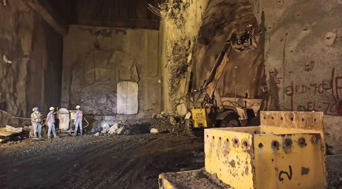
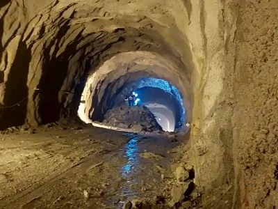
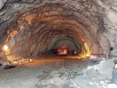
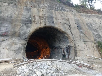
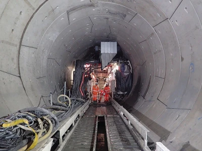
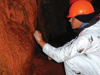
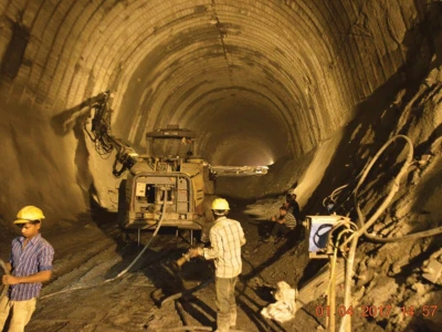
Tehri hydroelectric project is located on the left bank of River Bhagirathi in the state of Uttarakhand. Tehri Pumped Storage Project (PSP) comprising 4 Nos of reversible pump-turbine units of 250 MW each, involves construction of an underground Machine Hall, Upstream Surge Shaft with Chambers - 3 & 4, a Butterfly Valve Chamber (BVC), a Penstock Assembly Chamber (PAC), the Downstream Surge Shaft with Chamber - 3 & 4, a pair of Tail Race Tunnels (TRTs) and the Outlet structures. Execution of large infrastructure projects cannot be imagined without high- level engineering explorations, the prerequisites to increasing the economic efficiency of capital investments. Prior Estimate of uncertainties and risks involved in the construction process is central to decision making in the underground projects. In such Projects, a significant part of uncertainties results from unknown geological conditions. Timely calculation of risks and action required therein is vital in mitigating geological risks in the underground construction and tunnelling projects. Continuous updating of geological models, readjustment of excavation and support to actual ground conditions are the measures that control all geological risks at the site. In short, adopting appropriate excavation technology, proper sequences, dependable support, monitoring behaviour and auxiliary measures mitigate the geological risks to a great extent.

The present paper discusses advance identification of geological risks based on continuous updating of geological model of the site, design updating, and measures applied to reduce the risks in the Twin Chambers viz. Butterfly Wall Chamber (BVC) and Penstock Assembly Chamber (PAC) of Tehri Pumped Storage Hydro Project in the Indian Himalaya. The Paper also underlines the meticulous construction planning, on the spot resolution of the problem and visualisation of geological risks involved at every stage of design and execution.

Introduction
Layout of BVC & PAC CavernsFigure 1: Layout of BVC & PAC Caverns
The Twin-Caverns-BVC & PAC of size 78mx23.55mx10.2m and 83mx19.3mx13.3m of Tehri PSP project have been designed after the upstream surge caverns and before vertical penstock. The PAC cavern has been designed for erection facility, storage and maintenance of penstock liner of the upper horizontal and vertical portion of pressure shaft. However, the BVC cavern has been designed to control and regulate the flow and pressure of head race tunnel water before the penstocks. Both the caverns are to be excavated using “heading and benching system” and the “drill and blast methods”.

The Geological and Geotechnical conditions in these caverns are significantly worse than those of the other project components, because the axis of the chambers are sub- parallel to foliation plane and are found unfavourable in terms of underground excavation and support performance. Furthermore, multiple opening connected to both the caverns and to the extension of already constructed caverns of stage-1 project also makes it difficult and challenging for safe excavation.

Three-dimensional Geo model based on detailed sub-surface investigation has been developed to depict the actual sub-surface eo-conditions to the finalised excavation sequences and support measures. The behaviour of both the caverns has also been monitored during the excavation to ensure performance of the support system and additional support measure requirements.

Geological Model of the BVC & PAC
The alignment of the Twin-Tail-Race-Tunnel runs through the folded sequence of the low-grade metamorphic rocks of Upper Chandpur formation of Jaunsar group. The entire sequence appears to be monotonous in composition with variable proportions of argillaceous and arenaceous constituents, based on the predominance of particular constituent layers of the rocks of the BVC and PAC, differentiated into four main rock units: called Phyllitic Quartzites Massive (PQM), Phyllites Quartzites Thinly Bedded (PQT), Quartizitic Phyllites (QP) and Sheared Phyllites.

The Phyllitic Quartzite Massive and Quarzitic Phyllite (thinly foliated) is considered to good to fair rock class. However, the excavation through the Quarzitic phyllites and Sheared Phyllites termed as Poor to Very Poor rock class.

Sectional arrangement of BVC & PACFigure 2: Sectional arrangement of BVC & PAC
To explore the extension of these various rock units along the tunnel alignment and to minimize Geological risks in the process, detailed surface geological mapping and selected Geotech exploration was carried out and percentage and zones of each rock unit was established well ahead of the underground excavation.

a) Penstock Assembly Chamber (PAC)
The crown portion of PAC heading has been excavated throughout its length and supported with ISMB steel sets and 500mm C/C spacing, along with 25 mm thick SFRS. The lithological units QP, PQT and SP have been encountered in the excavated reach belonging to Chandpur Phyllites of Jaunsar Group. The rock mass is foliated, bedded, jointed, slightly weathered and sheared at places.

Two numbers of Sheared Phyllites (SP) zones have been recorded. These bands are about 2-3m wide, and are aligned along the orientations of N250°/65° and N180°/55°. In this section over- break has been recorded in the left side of the crown where SP stands exposed. Despite the extent of SP exposure, few shear zones have also been recorded.

Geological Model of BVC & PACFigure 3: Geological Model of BVC & PAC

The other SP occupied stretch has been encountered at the end of cavern crown portion where it is around 4-6m wide and oriented more or less along the bedding. This SP bands appear at the crown and terminate at the end wall. The remaining area is in QP and PQT. Additionally, a few quartz veins/intrusions have been found along foliation / bedding planes.

In general, the rock mass has been traversed by four sets of joints including bedding/foliation planes. Ten numbers of major shear zones were found intersecting the cavern during excavation. All the Shear zones were seen filled with clay gauge. The excavated crown portion was found to be dry to damp with no recorded flowing condition .

The rock mass classification is based on Rock mass Rating (RMR). It shows that the cavern of rock class IV and V (A) encountered

Construction sequence of PACPhotos 1: Construction sequence of PAC

b) Butterfly Valve Chamber (BVC)
The BVC underground chamber is currently under construction, located downstream of U/S Surge Shaft. The crown portion has been completely excavated in length and the remaining benching section of the BVC is still in progress. The alignment of the long section is bearing N3030. The crown portion of the BVC has been completely excavated. The lithological units of QP, PQT and SP have been encountered in the excavated reach belonging to Chandpur Phyllites of Jaunsar Group. The rock mass is foliated, bedded, jointed, slightly weathered and sheared at places.

A thick and continuous SP band has been located from the left centre crown portion (RD. 0m) and traced to the left the SPL at RD. 8m. Moreover, this band extends from RD. 8m to 22m in left SPL and crosses the centre line at RD. 21m and continues to the end of excavated stretch of the crown. The SP band is observed to be distributed randomly and does not follow any particular discontinuity set. A few quartz veins/intrusions have been faced along the alignments of the foliation and bedding planes.

Construction sequence of BVCPhoto 2: Construction sequence of BVC

Geotechnical Investigation

a) Drilling of Core Holes
Sub-surface exploration for any underground structure is done by drilling of core holes at different locations along the proposed alignment of the structure. Total 10 nos. of drill holes have been done to investigate the subsurface condition and behaviour of the rock mass.

b) Pilot Tunnel / Central Gullet
A pilot tunnel / Central Gullet was proposed in the centre part of both the chambers, i.e., BVC & PAC to verify the actual subsurface condition along the proposed chambers. From the 3-D geological mapping of the pilot tunnel, necessary geological information were obtained with reference to shear zones, strength of rock mass, seepage condition etc. This pilot tunnel extremely assists the designers for reviewing their support system.

Tunnelling Challenges and Excavation Methodology

a) Excavation of Pilot Tunnel and Adverse Geological Reaches
In the Ist stage, the excavation of approach adit to PAC & BVC was completed which is known as AA-3 & AA-2 respectively. After this excavation the crown was started through slashing of pilot tunnel in the IInd stage and completed as the designed support system of BVC. In IIIrd stage, the excavation of PAC crown was carried out through slashing of the pilot tunnel. Then excavation of Ist & IInd bench of BVC was done in the IVth & Vth stage and installed as the support system. After excavation of the PAC Ist bench stated in VIth stage. After this the excavation was done with alternate benching of the BVC & PAC along with the installation of the designed support system as mentioned in figure 4.

The Pilot tunnel was excavated, throughout its alignment, through a Poor –to-Very Poor Phyllite rock tunnelling- media. The proposed alignment of both the chambers is parallel to the strike of the rock bedding joints, considered to be very unfavourable tunnelling condition. Eight major shears, along with four minor shear zones, and one mega shear zone were faced during excavation of BVC. Four minor, four major and two mega shear zones were encountered during excavation of the PAC.

Very adverse geological conditions were faced in the BVC between RD 11m to 24m, RD 55m to 60m and in the PAC at RD 9m to 27m resulting from high concentration of Sheared Phyllite bands and shear zones. The rock class between the above mentioned RDs is “class Vth” having the RMR value 17-19. The rock-type is a thinly bedded PQT with Sheared Phyllite (SP), having <60 mm thickness. The UCS & RQD of the rock are 15-20 MPa & 10-20%. The joints are in- filled with clay gauge. Dampness has also been observed at many places. The joints are open: having 1-5 mm of opening, are smooth and slightly weathered.

After the excavation of the pilot tunnel of BVC & PAC, one row of design- rock bolts were installed at the centre of the crown together with a layering of ceiling shotcrete (SFRS).

After the excavation of the pilot tunnel, problems were anticipated with the joints / rock condition while side- slashing and bench-down time. Potential wedge formation in combination with other joints was also detected with the use of some software.

b) Downstream Wall Slashing
During the excavation of the pilot tunnel, controlled blasting with maximum pull of 1.0m was applied in view of the poor- to- very poor rock condition in the BVC & PAC. After excavation of each face, the rock mass was supported with the help of a layer of SFRS. After the successful excavation of the pilot tunnel, side-slashing was challenging; because critical joints, major to mega shear zones, and poor rock condition were projected in the walls while executing the side-slashing of the cavern.

D/S wall- slashing was done with the help of controlled blasting throughout the length of the chambers. Minor to major critical shear zones were mapped during the pilot tunnel- excavation along the bedding joints. Side slashing from D/S wall was done from RD 0m to 78.5m in BVC & 0m to 83m in the PAC. The top crown level of the BVC & PAC is 729.87m & 725.17m. The D/S wall -slashing of both chambers was done up to El 725.5m & 719.2m in the BVC & PAC respectively. During the scaling of the rock mass falling after the blasting, huge chunks of the rock fell due to the shear zone and weak rock condition at many places in both the chambers.

c) Upstream Wall Slashing
After completing the D/S side-slashing, a layer of shotcrete to seal the joints opening along with some temporary rock bolts was applied wherever required. Then U/S side-slashing work was executed with controlled blasting and temporary rock- bolt support wherever required. Design rock-supports were installed after the excavation of the heading portion of the BVC & PAC. Controlled blasting technique was also adopted during the right side- slashing of both the chambers.

The rock mass between RD 11m to 24m & 55m to 60m falls in a very poor rock condition, having a RMR value of 17-19 in BVC. The major rock type between these RDs were Sheared Phyllites having UCS & RQD <25MPa & 25% respectively along with the d ground water condition. The joints are open having an opening of 1- 5mm in- filled with soft filling with slightly rough and weathered condition. The remaining part of the BVC falls in class IV, having RMR value 23-26 showing better to slightly improved condition. After the D/S and U/S side- slashing of the heading portion, all design rock- supports were installed.

The rock mass between RD 9m to 27m falls in a very poor rock condition, having the RMR value 19 in PAC. The major rock types between these RDs are Sheared Phyllite having UCS & RQD

<25MPa & 25% respectively, along with a damp ground water condition. The joints are open having an opening of 1-5mm, in- filled with soft filling , slightly rough & weathered in composition. The remaining part of the PAC falls in class IV, having RMR value of 23-36 ,and shows better slightly improved condition. After the D/S & U/S side- slashing of the heading portion, all design rock supports were installed in the PAC.

d) Systematic Benching of BVC & PAC
The following sketch shows the systematic excavation plan of the BVC & PAC. After completion of the heading excavation of BVC & PAC along with installation of design support, the benching of BVC & PAC was started from El. 725m & 719m respectively. First, the benching of BVC D/S wall was started. The height of each bench was 2m. All the approved design support system was installed just after the excavation. After excavation and completion of all design -supports in Ist bench of D/S wall of BVC, the excavation of the U/S wall, bench of same level in BVC was started. After the D/S and U/S side -slashing up to El. 723m all design -rock support were installed. The same methodology for excavation and installation of the support system was adapted to achieve the invert level of 705.0m.

Support system arrangement of BVC & PACFigure 4: Support system arrangement of BVC & PAC

After achieving the El. of 717m in BVC, the excavation of PAC D/S wall benching was started. The height of each bench was 2m. After excavation and completion of all the design supports in the Ist bench of D/S wall of PAC, the excavation of U/S wall bench of the same level in PAC was started and achieved the EL of 717m. After completion of IVth bench of the BVC, the excavation of the Ist bench of PAC was started & completed along with all design support system. Thereafter, the Vth bench of BVC excavation started and the rock support work is in progress. When the support work will complete, the excavation of PAC IInd bench will be started. Hence, alternate excavation of benches in BVC & PAC is carried out to achieve the required level as shown in figure 4.

Distressing problem in D/s wall between El. 725.37m to El.723.87m (December 2016):(?) At RD 51.0m, two numbers of rock bolts were nailed. The bearing plates of these rock bolts were detached from the bars (Figure 6). Apart from that, the bearing plates of the rock bolts between RD 45.0m to RD 56.0m and RD 66.0m to RD 70.0m were showing bending along with few cracks (Figure 7). The rock type in this stretch mainly consists of phyletic quartzite, thinly bedded with sheared phyllite (PQT+SP) and the rock-mass class belongs to Class IV (mostly) and ClassV. Instrumentation monitoring through BRTs and MPBX is continuously being done, and no major fluctuations have been noticed during this period.

Cavities are mainly formed due to the presence of shear zones and seepage conditions. Most of the encountered shear-seams are major shears. A number of minor to major shear zones (clay filled) have also been encountered from the 3D geological logs of BVC & PAC. Geological mapping shows that most of the shear zones are aligned parallel to the foliation orientation. However, shear zones along other joint sets have also been mapped, but these are less frequent. The shear zones vary in thickness, ranging from 2 cm to 20 cm. Many shear zones are clay-filled and wet to damp from place to place.A lot of time was lapsed in treatment and crossing of shear zones.

In the initial stage, the crown of BVC & PAC was supported by a layer of ceiling shotcrete (SFRS). Then fixing of structural ribs ISMB 300 @ 600 mm c-c spaced & 500 mm c-c was spaced throughout the BVC & PAC crown respectively. After this, a 32mm dia., 8m long & 1.2 m c-c & 1.0 m c-c spaced rock bolts are fixed in BVC & PAC respectively to protect the crown.

After the completion of support system of the BVC & PAC crowns, the sequential bench excavation of BVC & PAC was started. Each excavated bench was fully supported just after the excavation & after this the excavation of next bench was started.

The BVC U/S wall was supported by a 150mm thick SFRS, along with 32mm- dia., 10m-long & 2m c-c spaced rock bolts from El 720m to 718m. In the BVC U/S wall, 133 no’s & 39 no’s of cable anchors, having a length of 12m & 14m respectively were installed between El 725m to 717m. The load bearing capacity of the cable anchors was designed for 120-ton capacity. The cable anchor was 2m c-c spaced in BVC. A total 377 numbers of Cable anchors were installed. At some locations bundle-anchors were installed in between the upstream and downstream walls of the BVC( between 724.0m to 719.5m).

The BVC D/S wall was also supported by a 150 mm thick layer of SFRS, followed by 228 nos of rock bolts, having 10 m long, 32mm dia. & 1.25m c-c spaced. Additional rock bolts were also provided in the D/S wall considering the low rock cover and poor geological conditions between BVC & PAC. The BVC D/S walls were supported with the help of an additional 60 nos of rock bolts, having a dia.of 32mm, length 10m & 2m c-c spaced and 115 nos rock bolts having dia. 25mm, length 6m & 2m c-c spaced. Total 57 and 19 m long cable anchors were installed from El. 722.5m to 717m in the D/S wall of BVC, having 120 ton designed load - bearing capacity.

In the PAC D/S wall, the Ist bench between El 719m to 717m was completed and supported by a 150 mm thick SFRS, followed by 54 nos of rock –bolts of 32 mm dia., 4m long & 1.5m c-c spaced. The U/S wall ofthe PAC Ist bench was supported by a 150 mm thick SFRS ,followed by 16 nos of rock bolts each having 32 mm dia., 8m long & 1.2 m c-c spaced. The aforesaid rock support was installed at El 717m in the BVC & the PAC. Furthermore , the same support system was installed in the BVC and the PAC up to El. 705.0m.

The following were the adverse conditions encountered during the excavation of the BVC:
  • Planar failure and toppling on the crown along foliation planes at some places
  • Formation of unstable structural wedges due to intersection of J1, J2 & J3.
  • Water dripping damp muck were found at some place.
  • The bedding and foliations are very unfavourable owing to the strike of the bedding and foliations, sub parallel to orientation of the chamber axis being N 303°
  • A number of minor, major and mega shears emerged through the entire excavated length.
  • The shears varied in thickness <15cm, along and cross, the bedding, and foliation joints.
  • The rock -mass has been intersected by two prominent set of joints
  • Bedding/foliation joints, silicification along foliation joints, and dipping towards N140° – 160° / 35° -45°, was prominently recorded.
Geotechnical Parameters
Two types of rocks, i.e., PQT and QP+SP were considered good for the 3-D analysis of the BVC and the PAC. The geotechnical parameters adopted for the 3-D analysis were provided by the design- consultant as mentioned in table number 5&6. The marked blast damage or disturbance zone was the first 3m of the rock surrounding the excavation.

Table-1: showing the geotechnical parameters in BVC/ PAC
Rock Category Parameters Units PQT
(Isotropic/ Oriented)
QP+SP
(Homogenous)
Intact Rock GSI - 50 25
mi - 10 10
UCS MPa 45 25
Poisson’s Ratio - 0.22 0.25
Bulk Density kN/m3 27 27
Overburden depth m 330 330
3-D Modelling of Butterfly Valve Chamber (BVC) & Penstock Assembly Chamber (PAC)
Geological model of Butterfly Valve Chamber size 78.51(L)x 13.0(W)x 19.35(H) & Penstock Assembly Chamber size 83.10(L) x 13.0(W) x 19.35(H) have initially been conceptualized based on 3- D geological logs of Adit AA-3, AA-2, PAC drift, 3-D log of U/s BVC Drainage gallery, and the Drill hole logs of CH-4, CH-5, CH- 6, CH-12, CH-13 & CH-12b.

However, the geological model was further modified depending upon the geology encountered & recorded during the 3-D geological logs of the overt portion of the BVC & the PAC.

As per the 3-D geological log of the overt portion of the BVC, two types of rock variants QP+SP & PQT+SP were discovered. 86% length of the cavern belongs to the PQT+SP rock mass. However 14% of the length belongs QP+SP rock- mass. The QP+SP represent the Quartizitic Phyllites rock, highly weathered and sheared in nature, closely to moderately spaced and of the medium persistence rock- mass. The strength of the rock- mass belongs to the R2 grade (weak strength <25 MPa). Very poor RQD (<25%), slightly rough and undulating surface, with soft to hard filling discontinuities define the features of the rocks.. These properties of the rock- mass are classified as the poor ground media for excavation.

The PQT+SP represents Thinly foliated Phyllitic Quartzites , highly weathered & sheared, closely to moderately spaced and the medium persistence rock mass. The strength of rock mass belongs to R2 grade strength <25 MPa). Very Poor RQD (<25%), smooth & planner surface, with soft (clay)- filling discontinuities. These properties of the rock mass represent very poor ground media for excavation.

As per 3-D geological log of the overt portion of PAC, four types of rock variants QP+SP, QP+PQT & PQT+SP were encountered. 37% length of the chamber belongs to QP+PQT rock mass, 30% composed of PQT+SP, 33% belonged to QP+SP rock mass. The QP+SP represent Quartizitic Phyllites- rock , highly weathered and sheared , closely to moderately spaced and of the stuff of medium persistence rock- mass. The strength of the rock mass belongs to the R2 grade (weak strength <25 MPa). Very poor RQD (<25%), slightly rough & undulating surface, with soft to hard filling discontinuities are the properties of rock mass defined as the poor ground media for excavation.

The PQT+SP represents Thinly foliated Phyllitic Quartzites of highly weathered & sheared, closely to moderately spaced & medium persistence rock mass. The strength of rock mass belongs to R2 grade (strength <25 MPa). Very Poor RQD (<25%), smooth & planner surface, with soft (clay) filling discontinuities. These properties of rock mass represent very poor ground media for excavation.( Repeated)

QP+PQT represents assembles of Quarzitic Phyllites & Thinly foliated Phyllitic Quartzites, closely spaced & medium persistence rock mass. The strength of rock mass belongs to R3 grade (strength 25-50 MPa). Poor RQD (25-50%), slightly rough, undulating surface, with hard (rock floor) filling discontinuities. These properties of rock mass represent poor ground media for excavation.

Table-2: showing the Percentages of Rock Variants in BVC
Sl. No. Rock Variants RD/ Elevation Percentages
1. PQT+SP 67.5 m 86 %
2. QP+SP 11 m 14 %

Table-3: showing the Percentages of Rock Variants in PAC
Sl. No. Rock Variants Chainage/Elevation Percentages
1. QP+PQT 31m 37 %
2. PQT+SP 25 m 30 %
3. QP+SP 27 m 33 %
Construction Stages & Monitoring
The Geotechnical Instrumentation plays a vital role in evaluating the structural performance of an underground structure. The natural ground or rock mass tends to deform and de-stress when subjected to excavations, foundation and other loadings. Activities like squeezing, swelling and creeping, depending upon the mechanical characteristics of the material, are also responsible for the disturbances inside the underground rock mass. The monitoring instruments installed till date at various locations in the BVC & PAC are mentioned below.

a) Bi-Reflex Targets
Bi-Reflex Target consists of reflector plate mounted on a robust frame. The target has reflectors on both sides and is mounted on a universal joint such that it can be oriented in any direction as required. The target has a cross mark to allow precise targeting. The BVC has demonstrated maximum target movement of 130 mm at T4 (D/S) at RD 35.6m in D/S wall which seems to be stabilized in last couple of months.

In the PAC opening the maximum cumulative movement is 49.75 mm till date, no significant movement has been observed since last month at T2 (D/S) target at Rd 30.32m

b) MPBX
MPBX anchors are installed in the BVC and PAC, based on approved drawing as shown in figure 10 (i) and (ii). The MPBX anchors were installed at 04 points i.e., 2m, 5m, 10m & 15m respectively at crown, D/S & U/S side walls.

MPBX deformations were also observed in D/S wall of the BVC at RD 35m, El 722.5m with a maximum displacement of 19.92mm in 15m anchor, i.e., relative conversion towards the opening. Both the crown and the upstream wall records indicate relative internal movement due to stiff support.

Instrumentation, and monitoring of cavernsFigure: 5 (i & ii), Instrumentation, and monitoring of caverns

MPBX deformations were also observed in D/S wall of PAC at same RD-6.18m, with a maximum of -9.66 mm in the 10m anchor. MPBX displacements in PAC indicate nominal increase of 0.07mm at RD 80.69m at 10m depth (Crown) till date. A maximum closer of 5.97mm is observed at 10m depth -anchor at RD 6.18m on the downstream wall till date .A 0.49mm variation was observed since last month.

Most of the MPBX deformation indicted closing of sensor, i.e., the installed supports are rigid and all internal movements are small and terminate at the walls, Hence, the PAC opening may be considered safe till date.

Installed targets and instruments in PACPhoto 3: Installed targets and instruments in PAC

c) Load Cells at Cable Anchors
Load Cells are installed at 08 locations in the BVC, installed with an initially provided axial tensile load which is recorded after the load reading becomes stable just after the installation. The load cells are installed in the BVC at RD 11m, 17m, 43m, 55m, 63m, 69m (El 715.25m,715.25m,719.5m,715.25m,719.0m) respectively in the D/S wall and Rd 32.0m,74m ( El. 717.50m) respectively in the U/S wall

In downstream wall of the BVC, a maximum cumulative load increment of 51.35 tons was observed at RD 43.0m with the decrement of -2.77 tons till date.

Maximum displacement in PAC indicates nominal increase of 0.07mm and RD 80.69m at 10m depth till date.

d) Load Cell at Rock bolts
Total 6 numbers of load cells were installed in the BVC and the PAC at 32 Ø rock bolts. A maximum load 2.97 ton was observed at Rd 18.9m & El. 712.5m U/S wall of the BVC. At Rd.13.12m & El.

711.9m decrease in load value of -1.1 tons was observed in the BVC U/S wall.

Installed targets and instruments in BVCPhoto 4: Installed targets and instruments in BVC

Conclusion
An adequate Geological exploration is the most effective strategy for reducing the effects of geological uncertainty, and it is also the basic tools for minimizing the geological risk in tunnelling. Uncertainties associated with underground construction can be managed by means of continuous updating of the design during subsequent construction stages. A continuous adjustment and readjustment of excavation support methods suited to respective rock mass conditions, contribute to the safe and economical tunnelling. Therefore, before starting the construction and finalising the design of any tunnel, it is crucial to develop an overall geological model, based on the surface and subsurface investigation. It can be concluded that a realistic geological model for these twin tunnels will function as a major tool to finalising the design of the support measures, to selecting excavation patterns, deciding the rounds of excavation in each rock class, and to minimising geological risk during tunnelling.

During the excavation of large underground caverns, identification of weak geological condition, selection of excavation methodology for geologically challenging reaches, and additional rock support system for treatment of adverse geological features are very significant. Temporary and additional rock support assessment is the central responsibility for treatment of geological features. Construction -stage geotechnical assessments were made, and suitable remedies were adopted, for example, detailed geological mapping and logging of cores. Excavation methodology for critical reaches and recommendation of additional rock support system for treatment of adverse geological conditions are very challenging. After completion of heading excavation of the chambers, the tunnel deformation monitoring instruments are installed ,i.e., BRTs, Load Cell, MPBX, and Tape extensometer. Based on the outcome of deformation data, the support design & excavation methodology was reviewed during the construction stage. Moreover, presence of shear seams and soft infilling, reduces the overall strength of the rock mass ,and these weak rock masses are stablized with the help of proper design and support systems like the additional longer rock bolts, and thick shotcrete.

Acknowledgements
Author is thankful to the THDCIL management, for providing all kind of support to carry out the work.

References
  • Bieniawski, Z.T. (1973). Engineering classification of jointed rock masses. Trans. S.Afr. Inst. Civ.Eng.15, 335-344.
  • Bieniawski, Z.T. (1979). The geomechanics classification rock engineering applications. Proc. 4th Int. Congr. Rock Mech., ISRM, Montreux, 1979, vol.2, 41-48.
  • Bieniawski, Z.T. 1989. Engineering rock mass classification: Jhon Wiley & Sons. New York, 272 p.
  • Detailed Project Report of Tehri PSP, Unpublished report.
Sela Tunnel Project - Overcoming The Impossible
The responsibility for construction and maintenance of Balipara-Charduar-Tawang (BCT) Road has been entrusted to Border Roads Organisation (BRO). The 317.520 km long road connects West Kameng and Tawang districts of Arunachal Pradesh to the rest

Read more ...

Slurry TBM ‘Channel Express’ launched by CRCHI for working in Water Supply Tunnels in Singapore
On February 1, 2023, CRCHI attended the launching ceremony of its Slurry TBM ‘Channel Express’. It will be used in the construction of key water supply tunnel project TWRP Pipeline Contract 1 in Singapore where it will bore 1.6km with the inner diameter

Read more ...

China’s Largest TBM - With Panda Face Emerges From Tunnel
On 12 December 2022 ‘Jinxiu’ - China’s largest EPB TBM developed by CRCHI - marked the first smooth breakthrough of the Jinxiu Tunnel, a key control project of the Chengdu-Zigong high-speed railway. Jinxiu is China’s largest diameter EPB TBM with

Read more ...

STRUCINSPECT Technology Transforms Inspection of Los Angeles Metro Tunnel Network
With drones, multispectral optics, and AI, Austrian joint venture transforms tunnel inspection in the US. The world’s first infrastructure lifecycle hub taps the rapidly growing global market for infrastructure inspections. The remarkable thing about

Read more ...

CRCHI showcases total solutions of Underground Engineering Equipment
China Railway Construction Heavy Industry Corporation Limited (CRCHI) brought the whole industry chain products and solutions to bauma CONEXPO INDIA 2023. CRCHI exhibited TBMs, drilling and blasting method equipment, cotton pickers, and other

Read more ...

Sandvik sets up new factory; hands over first ‘made in India’ tunnelling jumbo to KSR Group, Hyderabad
In a historic event held on 30th January, 2023 Sandvik proudly presented the key of the first ‘made in India’ DT820 Tunnelling Jumbo to Mrs. and Mr. Koneru of KSR Group, Hyderabad. The machine was rolled out from Sandvik’s newly set-up state-of-the-art

Read more ...

CRCHI Slurry TBM ‘Avni’ Helps Make a Breakthrough in Bangalore Metro Project
The 6.6m Slurry TBM developed by CRCHI exited the tunnel at Vellara Station, Phase II of Bangalore Metro in India, becoming the first TBM to complete the breakthrough for the whole line of the project. Avni is one of the four slurry TBMs provided by CRCHI

Read more ...

The Bolter Miner - A Technology Revolution for Roadway Development in Underground Coal Mining
In India, coal is still the primary source of energy; over the past few years, there has been quantum jump in coal production level, but it was mostly due to the high percentage share from the opencast sector. The country is witnessing a fast

Read more ...

CRCHI emerges as provider of total underground engineering equipment and solutions
China Railway Construction Heavy Industry Corporation Limited (CRCHI) showcased its comprehensive range of equipment and products at bauma that included solutions for the whole industry chain in the field of

Read more ...

Herrenknecht AG wins bauma Innovation Award 2022 for development of continuous tunnelling
Herrenknecht AG won the highly coveted award bauma Innovation Award 2022 in the category “Machine Technology” for the new development of continuous tunnelling. The award was given for the next innovation boost in the mechanized

Read more ...

The Genesis of Underground Engineering
Regardless of the tunnelling technology used, tunnel designers decide the future success or failure at an early project stage. In fact, designers are the real managers of tunnel construction. The choice of design together with selected contract model is

Read more ...

TBM driving under low overburden by adopting innovative methodology
TBM mining in urban areas particularly under low overburden (less than 0.5D, D = tunnel Dia) is a big challenge to design team as well as execution team. While working in a Lucknow metro project, the metro authorities encountered a stretch where TBM had to cross

Read more ...

Tunnel Ventilation System Basic Concepts and Designing Principles
The term ventilation combines several functions such as smoke extraction, pollution ventilation, and ventilation for environmental purpose. The design of a ventilation system is usually based on three scenarios: During construction: to provide external

Read more ...

CRCHI Mega Slurry TBM ‘Jinghua’ Assists the First Tunnel Section Breakthrough of Beijing East Sixth Ring Road Reconstruction Project
In September 2022, the Beijing East Sixth Ring Road Reconstruction Project reported another good news: the CRCHI mega slurry TBM ‘Jinghua’ smoothly reached the intermediate air shaft, marking the project’s achievement. The maximum excavation diameter

Read more ...

TERRATEC EPBMs ready to tackle Kanpur Metro’s 1st Underground Section in India
TERRATEC celebrated the successful site acceptance testing of two 6.52m diameter Earth Pressure Balance Tunnel Boring Machines (EPBMs) for Uttar Pradesh Metro Rail Corporation (UPMRC) for Corridor-1 of Kanpur MRTS Project (KNPCC-05) in India. The two 6.52m

Read more ...

Tunnelling Asia 2022 - International Conference on Underground Space
Tunnelling Asia 2022, organized by TAI, which took place in Mumbai during 27th and 28th June, saw a huge gathering of delegates/engineers from all around the world. The theme of the conference: ‘Underground Space: Need of the Day’ focused on

Read more ...

Hydraulic Heave Failure Mitigation Approach for the construction of the Deepest Metro Ventilation and Egress Shaft in India
Dr. Lakshmana Rao Mantri, Assistant General Manager (Designs), and Satya Narayan Kunwar, Project Manager, AFCONS Infrastructure Ltd. , discuss the design and construction challenges of constructing India’s deepest underground metro ventilation

Read more ...

Creating Zero-Carbon Tunnels
Despite a daunting timeline set by the Paris Accord, zero-carbon tunnels are within reach, provided the right solutions are implemented. Er. Vasileios (Bill) Paoulos, CMT, CMRL, L&T Construction Heavy Civil Infrastructure

Read more ...

Readily Biodegradable Soil Conditioning Foaming Agents - A New Technology
Mike A. Sposetti, Global Technical Manager TBM, Underground Construction, Master Builders Solution, Malta, and Manish Gautam, Product Segment Manager - UGC TBM Tunneling Projects, Master Builders Solution, Mumbai, discuss how readily biodegradable

Read more ...