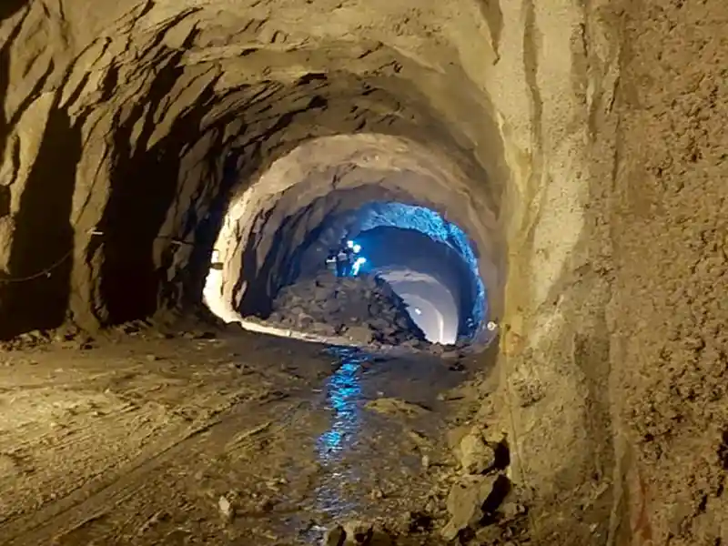
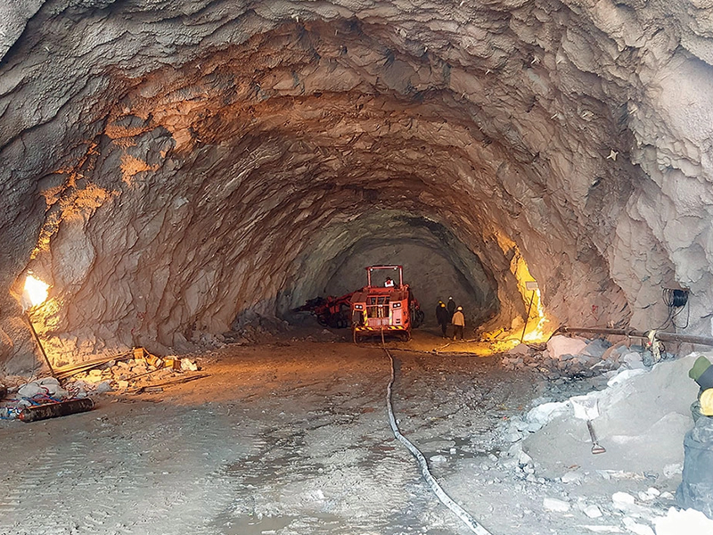
Importance of Pre-Injections Before Tunnel Front Advancement
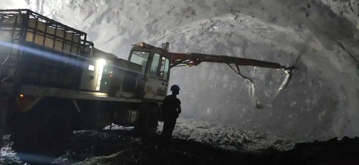
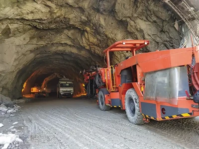
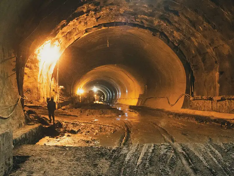
Pre-injections or injections ahead of the excavation face in underground construction can, in many situations, offer significant advantages. This is particularly the case in difficult ground conditions like severe water ingress or mechanically poor ground or soil, in which pre-injections can contribute to avoid mishaps and serious delays.
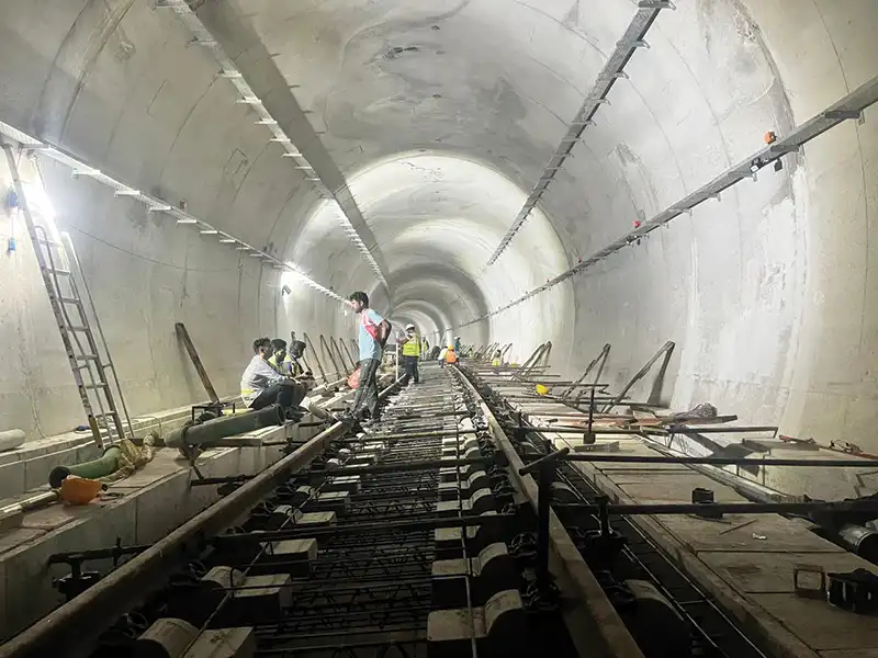
Pre-injections in underground construction have two main goals; either the reduction of the permeability in the ground and hence the reduction of the water ingress into the underground structure, or the mechanical improvement of a jointed or weathered rock mass or a soil by the penetration of a grout into the ground. Modern pre-injection technology involves the design of methods adapted to the encountered situation. This includes proper drilling techniques and drilling geometry for the best delivery of the grout into the ground, determination of relevant working criteria during the actual injection, as well as the employment of state-of-the-art injection products like special microfine cements and colloidal silica.
Published on:
14 June 2022
Published in: NBM&CW June 2022
Share:
We Value Your Comment