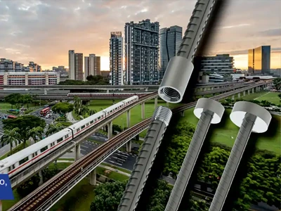
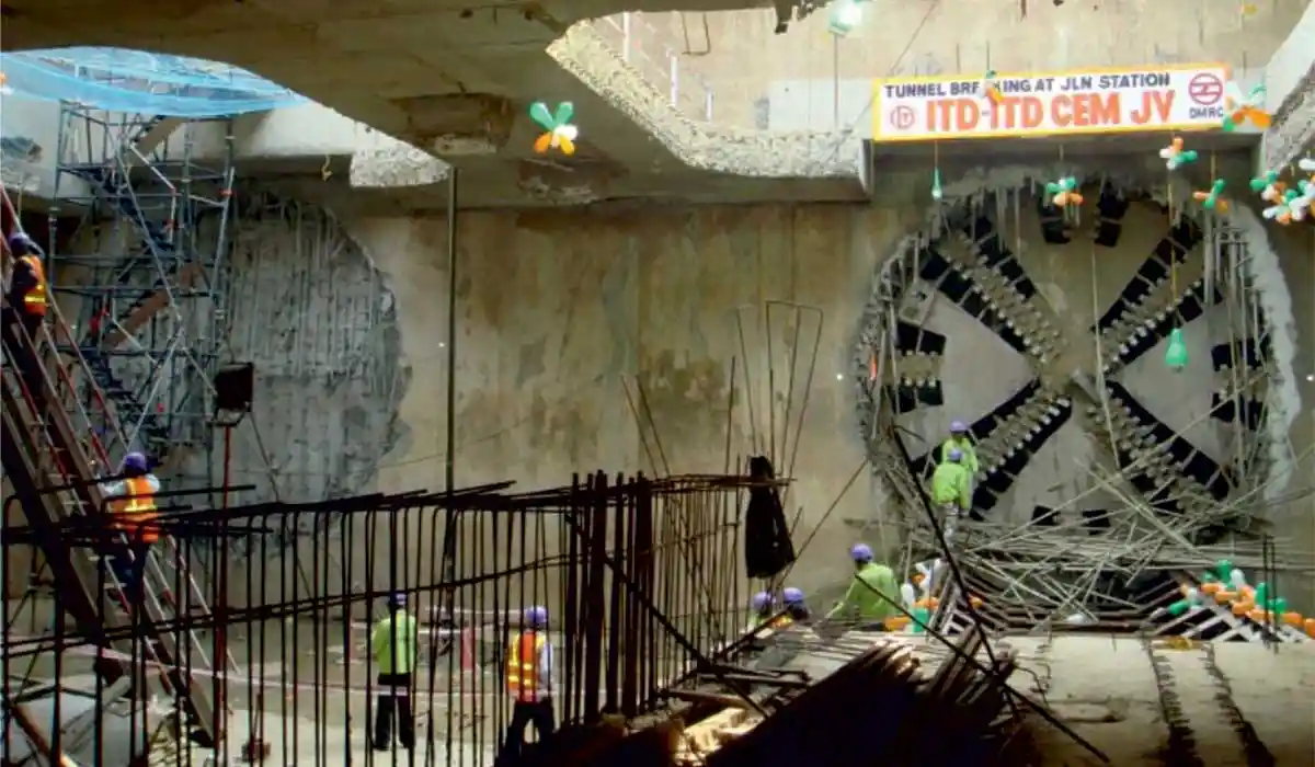
Vinay Gupta, Director & CEO, Tandon Consultants, discusses the intricacies and issues in the construction of underground metro stations including strata survey during structural design, selection of methods and techniques of construction, traffic management, handling of utilities, installation of diaphragm walls, launching and retrieving of TBM, manufacturing of precast segments and more.
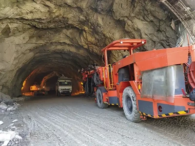
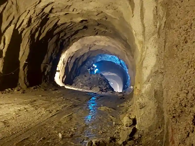
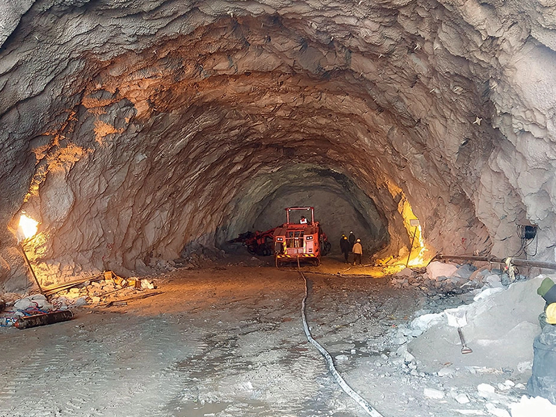
Underground construction poses several new challenges such as execution of Diaphragm Walls for Top-down or Bottom-up construction, Secant Piles for Bottom-up construction, Soldiers Pile-Wooden Lagging for Bottom up construction, etc. Installation of Diaphragm Walls is easy in soil sub strata, but extremely difficult in rock substrata. In such cases, use of Trench Cutter becomes necessary.
A new technique called Cube method involves construction of a shaft at each of the two ends of the Diaphragm Walls, and driving a tool horizontally between the two, keeping the upper strata undisturbed. Installation of Ground Anchors to control floatation and Rock Bolts to control lateral forces/sway of soil retaining system are intricate processes. Soft Eye comprising of Glass/Carbon Fiber Reinforcement is constructed within the retaining wall for the TBM to cut through the wall easily while entering the station structure. Tunnel Lining, Cross Passages, TBM Advancement, Tunnel Ventilation are some of the specific issues related to Tunnel Boring. Handling the traffic and utilities during construction require special careful planning to prevent any disruption to public life. Instrumentation and Monitoring are other important aspects of underground construction.
Underground Metro Station
A typical underground metro station has a main station body of about 20m width and 250m length with two levels below the ground, lower level for track and platform, and upper level for concourse (paid & unpaid areas). The main station body is flanked by four or more entry-exit structures connecting ground level to the concourse. Figure 1 depicts a typical station footprint. Figure 2 shows an inside view of the concourse and platform levels (with a large opening at the concourse level).

Top-down Method of Construction
Top-down method of construction is more common as the ground above is usually required for traffic or other uses during construction. This method requires the use of RCC Diaphragm Walls (Figure 3) followed in sequence by the roof slab, the concourse slab, and the base slab, wherein connection between the Diaphragm Wall and these slabs are achieved through reinforcement couplers (Figure 4). Use of Secant Pile wall or Contiguous Bored Piles as permanent wall for Top-down Construction is not in vogue yet.

Bottom-up Method of Construction
In locations where the ground is not required to be used during construction, or where there is hard rock at small depths, making a Diaphragm Wall difficult, the conventional bottom-up construction is used. In such cases, either we go for sloped excavation (not desirable for deep excavations) or the use of Secant Pile Wall, Contiguous Bored RCC Piles or Soldier Pile-Wooden Lagging system (depending upon the suitability). Figures 5 & 6 show soldier pile-wooden lagging and contiguous bored pile, respectively. Similarly, figures 7 & 8 may be referred to for Secant pile and lateral bracing system, respectively.


Analysis
The main aspects of the analysis are soil and water pressure at every stage of construction. The sub-surface profile requires utmost care in deciding the corresponding design parameters. Complex 3-D analysis models associated with such structures is shown in Figures 9 & 10, which are generated with various loading combinations. Some of the useful tools to analyse correctly the structure for its interaction with the adjoining soil are Wallup and PLAXIS. General purpose software like STAAD and MIDAS are used for service stage analysis for its superimposition with the construction stage analysis.

Launching of Tunnel Boring Machine (TBM)
The other important area of concern is the location of launching and retrieval of Tunnel Boring Machine (TBM) used for tunneling. Usually, this area is maintained at the end part of the station body as depicted in Figure 11 - sometimes a separate structure, depending on the construction sequence. Once the end wall of the station launching retrieval area is constructed the TBM is required to penetrate through it to move (Figure 12). A Soft Eye comprising Glass Fiber reinforcement or Carbon Fiber reinforcement is incorporated in the Diaphragm Wall that can be cut by the cutters of TBM for it to advance through.

Drive Through & Drag Through
One of the common methods of launching and retrieval is to make launching shaft (LS) and retrieval shaft (RS), respectively (usually at the last 15m part of the station structure) and later used as an area for housing various services. This entails launching, retrieving, and again launching the TBM, which consumes time, but is cheaper.
However, in cases where construction timing and sequence demand earlier movement of the TBM, other methods of TBM movement such as Drive Through (Bore Through) and Drag Through are used. When the station body is ready fairly early, we can go for Drag Through type wherein the TBM is moved over the already cast base slab of the station using bottom-up construction (Figure 13).
On the other hand, when the station is expected to be delayed somewhat, we drive the tunnel through (Bored Through method) with sacrificial tunnel segments to be removed after constructing the station structure (Figure 14). This is more expensive due to the sacrificial segments but needed in certain circumstances. On the whole, there are many issues involved in UG Metro Stations that require careful planning and conceptualisation.
Planning of Tunnel Movement
The entire construction scheme depends on the planning of TBM movement. As explained above, the station may have LS and RS for launching and retrieving the TBM, respectively. Or drag through or bored through method may be used. Sometimes, the non-availability of TBM in the initial phase may affect the construction planning. The designer has to design the structure suited to the construction type and sequence. Figure 15 below depicts TBM movement for a stretch.

Sometimes, a separate LS or RS is constructed to launch or retrieve the TBM when none of the above techniques are found difficult. The LS / RS is used as Vent Shafts which are necessary for the Tunnel Ventilation System (TVS).
Manufacturing of Tunnel Precast Segments
Figures 16 & 17 depict the method of casting in a steel mould and of stacking them.

While the segment (a shell element) is cast in one orientation, it needs to be rotated to upside down orientation. It is done by a different mechanism wherein a vacuum lifter is used (Figure 18) and a special rotating bed is used for the rotation (Figure 19).
Conclusions
There are many intricacies in the construction of underground structures. The method to be adopted needs a careful consideration of the available site, construction equipment, and the timeline of each element. The structural design needs to cater to every construction scheme. Geotechnical aspects and ground water table play a vital role in the design and economics. Some of the smart software tools have made it possible to analyse and design complex underground structures.
Taking a cue from Paris and London – cities that appear neat and clean with their metro rails running underground - India is moving in the same direction and constructing a large number of metro projects all over the country.
About the author
