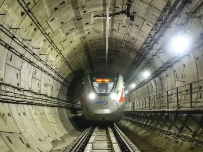
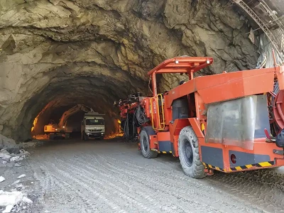
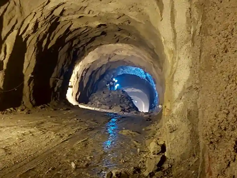
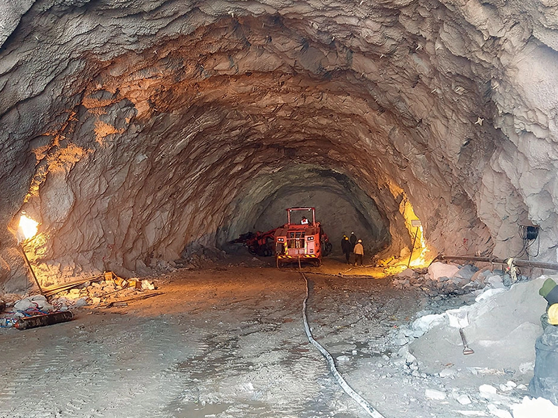
Tunnel Boring Machine (TBM) is a huge investment but is being adopted for enabling safe and speedy construction of tunnels. However, when unforeseen and unfavourable conditions are encountered, it is important to mitigate the issues immediately with quick and meticulous planning since, tunnelling below residential buildings involves high risks and challenges.
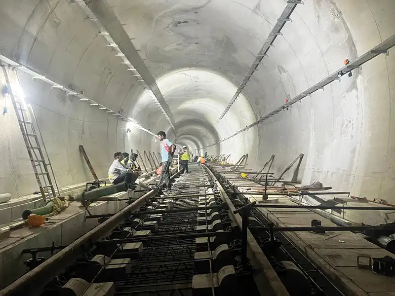
For the construction of JPW to Krishna Park Downline Tunnel of Package DC-06, a 5.8 m internal diameter tunnel was excavated in sandy silt and silty clay strata. Since the tunnelling was done in soil strata having low plasticity and the water table being up to crown, the earth pressure balancing method was adopted to eradicate the issue of over excavation, sink holes, and heaving.
TBM Tunnelling
Tunnelling starts with selection of tunnel boring machine as per strata and design for tunnel alignment.
Table 1: Selection of TBM for soft soil/mixed soil on the basis of grain size distribution.

As per GIR conducted prior to commencement of tunnelling work soil strata identified in report is ML, CL type with low plasticity and water table was found to be up to tunnel crown, and the operation of TBM had to be carried out in saturated condition. Hence, as per above analysis earth pressure balance TBM was recommended for this drive.
Few important components of EPB tunnel boring machine are shown below:

Challenges that affected TBM work
- Crossing of infringing sewer line (1800mm dia) in Tunnel Alignment.
- Heavy water ingress from tunnel eye while breaking of D wall for upline tunnel drive.
- Settlement of ground due to water and soil ingress during TBM operation.
- High thrust and torque while driving in closed pressurised mode.
The downline tunnel construction was of 1400 m in length and TBM breakthrough was scheduled for 13 September 2021. On September 03, 2021 at ring No. 961 the TBM machine encountered a trunk sewer of 1800mm dia RCC pipe having 40mm CIPP lining at a depth of 10 m from ground level. The TBM was not designed for cutting this RCC hume pipe having 40mm CIPP (cured in place pipe) lining. With this infringement, the breakthrough was delayed by almost 3 months.
In order to proceed with TBM tunnelling, taking out of this huge pipe was very essential. Since the line was at a depth of 10 m below the existing ground level and was very old and filled with sewer sludge, a detailed scheme was developed, and meticulous planning was done for this activity. The work was carried out in the following stages:
- Preparation of drawings with layouts
- Detailed drawings for pit construction above sewer line
- Detailed scheme for backfilling the pit after removal of pipe by means of suitable material to provide the required cushion/overburden for TBM drive.

Methodology Adopted for Crossing the Sewer Line
As the pipe was RCC and additional CTPP lining was there, it was not possible to cut through it with the TBM. To overcome this issue, the pipe had to be dismantled before crossing by the TBM. The following sequence was adopted during execution of the work:
- Pit construction: The pit for exposing the sewer line was constructed with confined excavation by soldier piling and strut/waller method as per approved drawing ‘A’ above.
- Lifting of infringing length of pipe from pit: After exposing of pipe, in order to lift the required length of pipe the stages were followed as mentioned in drawing ‘B’.
- Backfilling of pit: After removal of pipe, the pit had to be backfilled in order to ensure soil mass above tunnel crown. Backfilling work was carried out by plugging the pipe at both ends with the help of sandbags and lean concrete/sand soil was backfilled into the pit in layers so as to ensure that the required overburden / cushion for TBM drive was available.

Heavy water ingress from tunnel eye (an opening in D-wall for entry of TBM into soil)
- Launching shaft of DC-06 project was pre-constructed in Phase III project for CC-34 with RCC D-wall. In order to construct the tunnel eye, D-wall had to be demolished up to the size of the TBM dia. Since water table was up to the crown of tunnel, and in order to prevent sudden ingress of water and soil while breaking the D-wall, concrete micro piles (slurry pile) were driven in three layers just ahead of D-wall.
- But after completion of 90% cutting of tunnel eye, there was sudden ingress of water/mud into the shaft from the bottom portion of tunnel eye. Dewatering work was carried out by deploying required capacity pumps. Dewatering was done continuously for a period of 10 days by using 3 pumps of capacity of 15 hp, 25 hp and 35 hp.
- Large quantity of cementitious grout was pumped in order to arrest the flow, but after failure to plug the ingress of water, a concrete barrier wall of 500 mm thickness at the face of tunnel was casted up to 4m height, after which the water ingress stopped.
- After a few days, the water ingress channelized to some other areas, where valves were provided to divert the flow; however, the flow was less as compared to previously encountered. The work of tunnel eye breaking resumed and the successful drive of TBM was done on 9 March 2022.
- Care was taken after removing reinforcement. The TBM was pushed inside the tunnel eye, flapper plate and rubber mat bent towards the direction of TBM movement creating a one way valve type of condition to provide proper sealing for facilitating annulus gap filling. Also, the flapper plates were welded with each other throughout to ensure that they did not open up.
- After achieving the above, dual component grout was injected from tail shield of TBM after erection of third permanent ring.

Settlement of ground due to water and soil ingress during TBM operation
Since the water table was high, it resulted in increased pore water pressure and face pressure in front of TBM cutter head.
Balancing of earth pressure with the help of TBM is based on the pressure of earth available at face of the TBM. In order to counter this, pressure chamber is filled with muck and air pressure. This pressure must be 0.1 to 0.2 bars above the face pressure. As much higher pressure also results in heaving phenomenon and lower pressure, it could lead to sink hole.

Pressure of chamber is maintained using screw conveyor gate opening ratio as it regulates the quantity of muck coming out from chamber. Therefore, this theory of balancing pressure helps in overcoming challenges such as sink hole or heaving. Due to this principle of balancing the pressure this TBM is known as Earth Pressure Balance Machine.
Also, earth pressure balancing was ensured with the help of proper soil conditioning and regular monitoring of excavated earth volume.
High thrust and torque while driving in closed pressurized mode
During balancing the earth pressure, the quantity of muck stored in chamber is 20 to 22 cumec. As the soil is retained in the muck chamber (bulkhead) it increases the load on drive motors, resulting in increased torque and thrust pressure.

To overcome this issue, an additive in the form of (surfactant + water + air + polymer) was used and found to be favorable for sandy silt and soils of low plasticity. This additive helps in altering the soil rheology as well as density of soil. The surfactant is mixed with water and air is introduced in it to form bubbles which help in reducing the density and mass of soil, which helps in reducing friction at face and also results in reduced load on drive motors and thrust reduction.
Conclusion
Tunnelling activity gives various unforeseen challenges and also requires very close monitoring of all parameters to ensure smooth and hassle-free drive of TBM. Any issue during tunnelling can become a major threat in residential areas.
About the Authors:


